Canyon and company,
How are your EBC settings holding up?
I suspect you're not getting steady boost numbers as the days got colder and warmer?
So I've had the Perrin EBCS Pro for about 2 years now.
http://perrinperformance.com/i-14286955-ebcs-pro-universal-electronic-boost-control-solenoid.htmlMy results have been "no change" from the FM supplied EBCS. I spent the last month or so (since it's been getting warm) trying to dial it in, high P, low P, high D, low D, 32hz, 256hz, 64hz, changing thresholds, changing min/max solenoid controls, etc. The results have been identical to anything anyone has tried with the Ingersol valve. Boost control simply doesn't work well outside a pretty narrow min/max DC chart which doesn't compensate well for changing conditions.
There is a minority report though:
Most of my testing was done on the freeway, in 6th gear, rolling on the throttle to full throttle. In that situation, the EBC overshoots everytime except when max DC is set low enough to effectively make it open loop. The "minority report" is this: when still driving down the freeway, I did a 6-4 rev matching downshift before punching the throttle to see what would happen on the logs. The results were very surprising - a nearly perfect hit with almost no overshoot, and steady boost until I let off the throttle, all while staying well clear of the min/max DC settings. Exactly what the EBC is supposed to do in that situation.
This made me curious, so I tested farther.
With P I D settings set to 2-0-5, and frequency at 64hz, I did a 6th gear freeway roll-on. The resulting PID Integration sum and PID control % really laid out what was happening in a "clear as day" fashion. The PID control is incorrectly designed to continue to increase the duty cycle until boost exceeds the boost target.
The entire PID calculation is self integrating.
For those without a calculus background, what that means is that the result of each PID calculation is ADDED to the previously calculated result. The duty cycle of the EBC is never reduced until the boost exceeds the target boost. What is supposed to happen? Each new PID calculation is supposed to REPLACE the previous PID calculation.
Here is what I witnessed in my 2-0-5 example: Upon application of full throttle, the PID calculation begins at the minimum DC as defined by the EBC Min Duty Cycle table. It then adds duty cycle slowly, which resulted in wastegate boost pressure, or slightly higher, until the total duty cycle hit about 40%. At that point, the boost immediately begins to climb, while the EBC duty cycle continues to climb. Pretty quickly, the EBC passes 75% DC, and by this point, Boost pressure has crossed the target boost line of 12psi. Only when the boost pressure exceeded the target did the EBC Duty cycles begin to decrease. By the time the duty cycles decreased enough to slow the increasing boost pressure, the overboost ignition cut was hitting at 15psi.
What *should* have happened in this scenario, was an instantaneous increase in DC for the EBC, followed by an increase in boost pressure. As the boost pressure increased, the DC of the solenoid should have quickly decreased, long before ever reaching target boost. This represents a PID controller whose P value and total DC decreases as the error (error: difference between boost target and boost pressure) decreases.
Unfortunately, as the boost pressure nears the target boost, the duty cycle of the EBCS does not decrease, is simply increases more slowly as the error is reduced.
The PID calculation is supposed to calculate the result of the P, I, and D values, and then replace the results of the previous PID calculation - instead, it ADDs those two together.
The result is a controller which is not a P-I-D ("Pee Eye Dee") controller, but rather a I-I^2-D ("Eye Eye-Squared Dee") controller. That is to say that not only does our EBC NOT have "P control" (The most important part of the PID equation), but it provides an "I" control wind-up double whammy. What we thought of as the P control exhibits "Proportional windup" - which isn't actually a real-thing (It's really integral windup), and our I control experiences "Integral Windup Squared". (The I term is supposed to continue adding to itself, but because both the I and PID terms add to themselves, the I term both adds to itself, and then adds to the sum of it's previous self additions.)
The inherently stabilizing effect of the D term means that it generally doesn't add up, but even at full go, it will never be powerful enough to overcome the wrongly-integrating PID sum which has built up over time.
When I hit the 6-4 rev-matching downshift on the highway, I didn't give the system any "wind-up" time; I effectively allowed the P term to do what it's supposed to do, and the D term properly arrested it from overshooting.
When properly executed, there is never a need for "minimum and maximum Solenoid DC". Those were put there as band-aids to make a broken system seem fixable, making wind-up less debilitating.
A correct PID system should probably have the following:
1 - A 2D table with "normal" values - or expected EBCS Duty cycle percentages for defined boost targets
2 - Instead of a minimum duty cycle table, a solenoid start, which is the lower threshold for boost at which point the EBC starts accepting PID inputs (for a boost target of 12psi, you might want the EBC to stay at 100% DC until, say 4.5psi)
A P-value is calculated based on boost error versus normal value:
You might define your "normal" for a boost target of 12psi to be 53% duty cycle.
Boost error is calculated as boost target minus boost pressure.
When boost is low (perhaps 5 psi) the controller might be throwing 98% duty cycle at the EBCS.
As boost approaches 12 psi, your EBCS Duty cycle appoaches 53%.
If atmospheric conditions dicatate that you only needed 50% DC to make 12 psi of boost, your EBCS slightly overshoots your target and slowly moves back towards the target before settling above your target.
If atmospheric conditions dictate that you needed more DC, (perhaps 60%), then your EBCS undershoots your boost target, coming to rest below your desired boost.
The I-Value is calculated based on boost error over time, and does not rely on "normal" value:
While boost is below the boost target, the "I" or "Integral" term, Integrates - that is to say it increases over time. During spool up, this "integral windup" can have hugely negative side effects in theory, but in practice, the P term actually compensates to remove a great portion of wind-up.
The intent of the I term is to eliminate error from overshooting/undershooting the normal value. If the "normal" term is too high, the P value is prone to overshooting. The I term is what pulls this overshoot back toward the target boost. The opposite is true if your normal value is too low, the I term pulls the undershoot up towards your target boost.
The I value and the P value have a relationship which is difficult to explain in words, but mathematically simple. In the case where the "normal" value is too low to reach the boost target in a given atmospheric condition (such as an extremely hot day), the P value will quickly get the EBCS Duty cycle close to the target. Once at the target, the I value, which has been integrating since PID control was activated begins to add to the EBCS duty cycle, effectively lowering the error. As the I value decreases the error, the P value provides less input towards the target. What is important to note is that the change in the I value towards the target will always be more significant than the change in the P value away from the target. Eventually, the the I value builds until the P-correction becomes zero. It's hard to explain, but I'll show it in a chart.
First, what a boost pressure versus boost target might look like for a "normal" set a little too low.
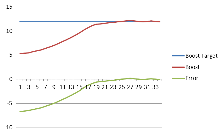
And second, what the I and P correction values would look like (on top of our "normal" value of +53) to get to the target boost.
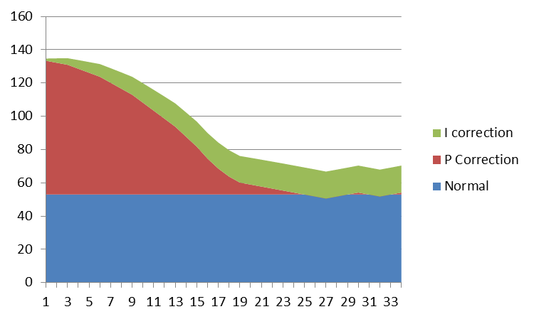
Note that since the EBCS can never exceed 100% Duty cycle, any corrections to more than 100% will simply max out at 100%
Ideally, you want as high an I value as you can get while not seeing noticeable windup during your longest spool ups (6th gear roll on, high altitude, hot weather), and then adjust your P value to achieve the quickest non-overshoot in cold weather, at low altitude, on a downshift. In a perfect world, if calibrated this way, you would never have to worry about the D term - but the stabilizing effect of the D term lets us get away with a pretty decent margin of error, preventing gross overshoots from oversetting our P value, and stabilizing rapid oscillations.
Using the knowledge I have gained through logging and thinking things through, I decided to try my own hand at Hydra EBCS. I changed my EBCS output from "boost control" to "3D PWM". For my PWM chart, I used "boost target, final" for the X axis, which calculates all the fancy boost numbers you put in for gear based trim, tps based trim, etc., to get your final boost target. I then used "boost pressure" for the Y axis. Wherever I landed on the 3d PWM gave me the difference between boost target and boost pressure. I then guessed a "Normal" value for the various boost levels represented on the 3d PWM target boost axis. I put those "normal" numbers in the cells which corresponded with identical boost target and boost pressure. So a cell which shows a boost target of 12psi, and a boost pressure of 12psi, received my "normal" for 12psi, which I guessed to be about 67% Duty cycle.
From there, I decided on a P value, and through the magic of excel, I determined how much DC to add or subtract from the 67% based on how far away from my target of 12psi I was. The higher the measured boost, the lower the DC, and vice versa. At lower throttle levels, I have lower boost targets (TPS Based boost), and therefore my lower normal number is placed in the appropriate cell, and calculations are determined from there.
What I ended up with was a crude "P" controller, which compared my target to my actual to get an error, and that error was added to my "normal" to get proportional control. It's nowhere near as good as a true PID controller, but it's a zillion times better than an I-I^2-D controller. Until Hydra puts a real PID function into the Nemesis, I'll have to resort to my crude P controller. It works...well enough to move onto other things for a little while...


