93' Miata stolen and flipped build thread

 03-14-2014, 12:49 PM
#1642

Also it looks like I've sprung a small leak in the transmission. How tight does this bolt need to be? Is there a gasket/crush washer that goes under it?
It has leaked about a tablespoon of oil since I filled it up.
[IG]https://www.miataturbo.net/attachment.php?attachmentid=106033&dateline=139476 8676[/IMG]
It has leaked about a tablespoon of oil since I filled it up.
[IG]https://www.miataturbo.net/attachment.php?attachmentid=106033&dateline=139476 8676[/IMG]

so you'll be the one that gets the honor of installing my long block into his car?
teehee

Reply
 0
0

0
03-14-2014, 01:13 PM
#1643
Elite Member
iTrader: (37)

Join Date: Apr 2010
Location: Very NorCal
Posts: 10,441
Total Cats: 1,899
I'm in the same boat, that's why I said to be damn careful. Sounds like he is talking about whatever switch that is.
While I'm on about that, what the hell is the 3rd electrical plug on the 6 speed anyway? I know where the VSS is and I assume one is reverse lights, but what is the 3rd?
/threadjack
While I'm on about that, what the hell is the 3rd electrical plug on the 6 speed anyway? I know where the VSS is and I assume one is reverse lights, but what is the 3rd?
/threadjack
Reply
0
0
03-14-2014, 01:17 PM
#1644
Elite Member

Join Date: Oct 2013
Location: Cedar City, UT
Posts: 2,764
Total Cats: 951
It is the Back-Up Light Switch that is on the lower passenger side of the transmission that I'm talking about.
Then you have the Speedo Sensor on the top of the passenger side
The Neutral Switch is on the drivers side top
Then you have the Speedo Sensor on the top of the passenger side
The Neutral Switch is on the drivers side top
Reply
0
0
03-14-2014, 01:17 PM
#1645

I'm in the same boat, that's why I said to be damn careful. Sounds like he is talking about whatever switch that is.
While I'm on about that, what the hell is the 3rd electrical plug on the 6 speed anyway? I know where the VSS is and I assume one is reverse lights, but what is the 3rd?
/threadjack
While I'm on about that, what the hell is the 3rd electrical plug on the 6 speed anyway? I know where the VSS is and I assume one is reverse lights, but what is the 3rd?
/threadjack
Reply
0
0
 Carry on with yo bad OCD self.
03-14-2014, 01:24 PM
Carry on with yo bad OCD self.
03-14-2014, 01:24 PM
#1648
Elite Member
Join Date: Oct 2013
Location: Cedar City, UT
Posts: 2,764
Total Cats: 951
The thing I will do when I remove it is add another inch to the wires of the switch so that when I tighten it it doesn't pull it taught.
Reply
0
0
03-15-2014, 04:09 AM
#1649
Elite Member
Join Date: Oct 2013
Location: Cedar City, UT
Posts: 2,764
Total Cats: 951
Not much done tonight, spent most the night studying the correct wiring for MS3x and the sensor grounds for the Brown analog sensor ground wires for the AFR/Boost gauge.
So from what I have read. You want to connect them into 2C & 2D black/green signal grounds off the ecu harness. Do I want to attach each brown wire into separate wires to reduce the noise of the signal? Or will attaching both gauges to the same point not affect "noise".
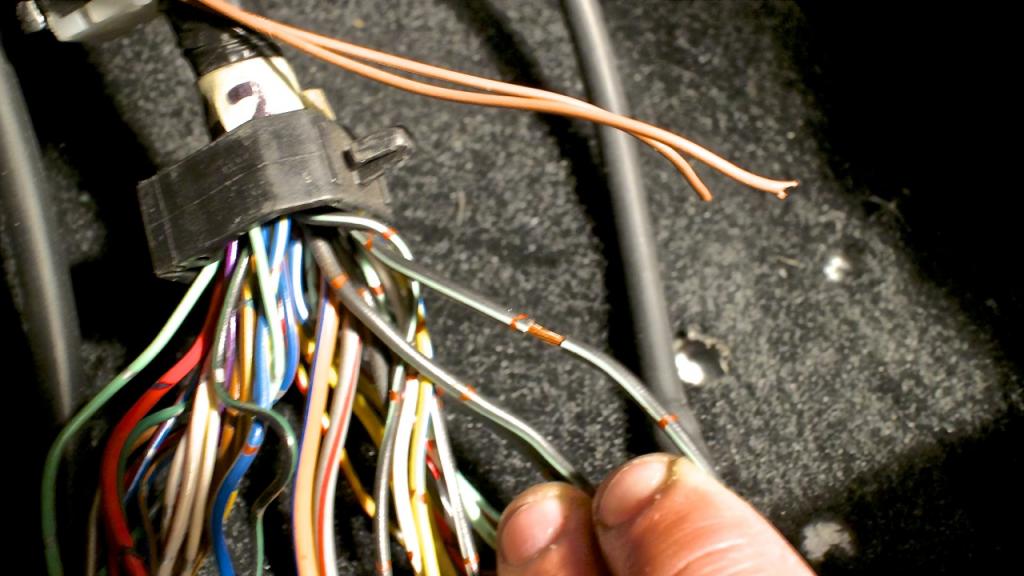
When I was looking at the ecu harness I also spotted this....this, does not look safe to me...at all. Or do a lot of people splice wires like this...
Then I started to track down all the problems with the wiring in the engine bay.
The pins are loose. Clip and replace with a undamaged from the 90 Miata harness?
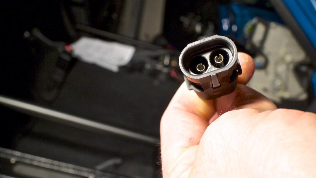
This comes out from the injector harness behind the VIC's solenoid.
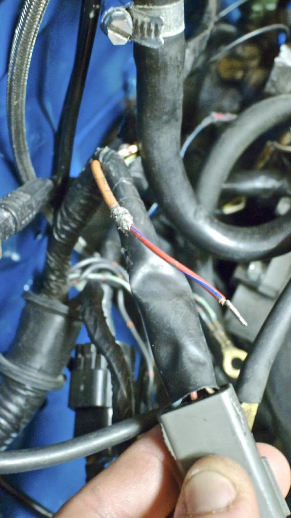
The VIC's solenoid. Red wraps around to the drivers fender and plugs into a blue single pin connector(although the connector is a 3 pin). Black I am pretty sure is the ground wire.
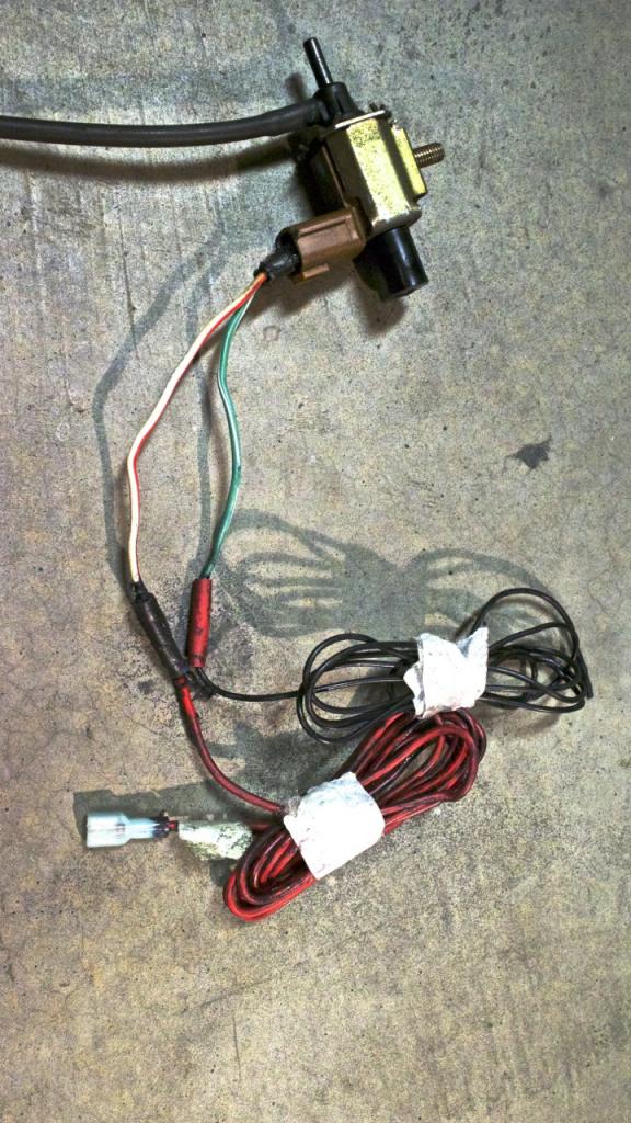
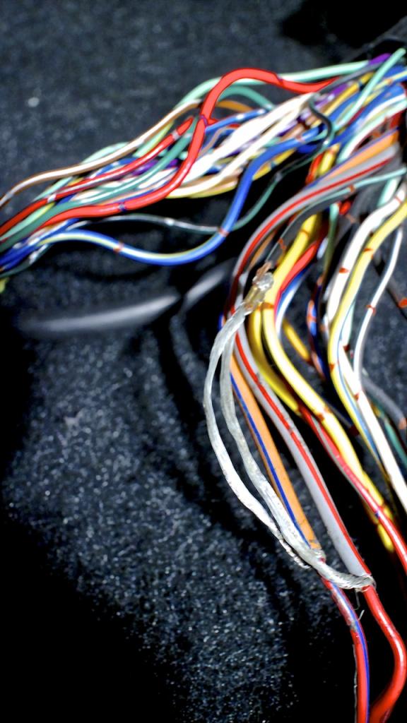
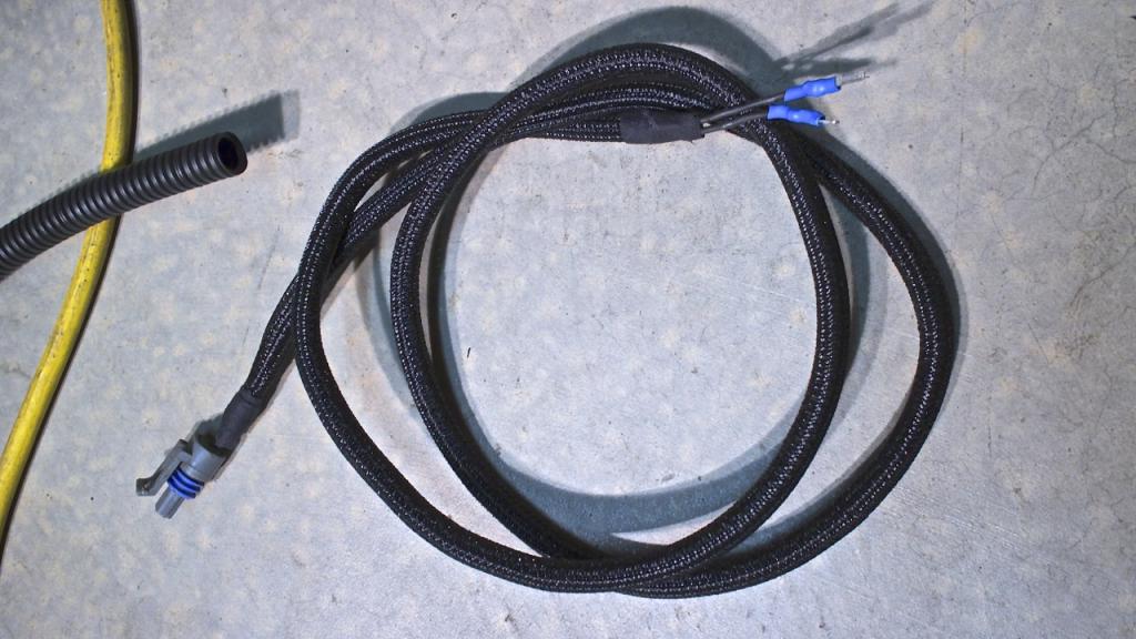
Fixed the AIT wires for the intercooler. It had unprotected loose wires just running to the intercooler, so I shrink wrapped them together and then put some of the new snazzy braided cable wrap on it. Also wrapped up the exposed pin connector the AIT harness goes into
Slowly but damn surely.
So from what I have read. You want to connect them into 2C & 2D black/green signal grounds off the ecu harness. Do I want to attach each brown wire into separate wires to reduce the noise of the signal? Or will attaching both gauges to the same point not affect "noise".

When I was looking at the ecu harness I also spotted this....this, does not look safe to me...at all. Or do a lot of people splice wires like this...

Then I started to track down all the problems with the wiring in the engine bay.
The pins are loose. Clip and replace with a undamaged from the 90 Miata harness?

This comes out from the injector harness behind the VIC's solenoid.

The VIC's solenoid. Red wraps around to the drivers fender and plugs into a blue single pin connector(although the connector is a 3 pin). Black I am pretty sure is the ground wire.

Fixed the AIT wires for the intercooler. It had unprotected loose wires just running to the intercooler, so I shrink wrapped them together and then put some of the new snazzy braided cable wrap on it. Also wrapped up the exposed pin connector the AIT harness goes into

Slowly but damn surely.
Last edited by Jeffbucc; 03-15-2014 at 04:53 AM.
Reply
2
2
03-15-2014, 06:24 AM
#1650
Elite Member

Join Date: Mar 2006
Location: Schwarzenberg, Germany
Posts: 1,553
Total Cats: 101

Now that is what I am talking about - thats the way I like a proper wiring!
Props of course!

That seem to be some shield wires, I have to look up the wire colours, to see what they are.
Could you have a look at which connector pin they end?
BTW, dammit that looks tasty... (Almost makes me wish I didn't hang myself yesterday due to the Brain...
 )
)
Last edited by Zaphod; 03-15-2014 at 06:37 AM.
Reply
0
0
03-15-2014, 11:15 AM
#1651

Slow and steady on the wiring. Get it all cleaned up. It pays dividends to not have to worry about poor quality wiring. Bad wiring is how cars catch fire.
I'm doing EXACTLY the same thing right now on the red car. I think I've removed more than 20 wire taps at this point, fixed insulation, done proper wire splices with solder and heat shrink, etc., etc.
Here's a link for a VICS connector. I was in the same boat, PO "RTV'd" the wires to the VICS solenoid. Ballenger Motorsports - High Performance Electronics
Reply
0
0
03-15-2014, 01:10 PM
#1652
Elite Member
Join Date: Oct 2013
Location: Cedar City, UT
Posts: 2,764
Total Cats: 951
I'm doing EXACTLY the same thing right now on the red car. I think I've removed more than 20 wire taps at this point, fixed insulation, done proper wire splices with solder and heat shrink, etc., etc.
Here's a link for a VICS connector. I was in the same boat, PO "RTV'd" the wires to the VICS solenoid.
Here's a link for a VICS connector. I was in the same boat, PO "RTV'd" the wires to the VICS solenoid.
Reply
0
0
 03-15-2014, 07:33 PM
#1655
Elite Member
Join Date: Oct 2013
Location: Cedar City, UT
Posts: 2,764
Total Cats: 951
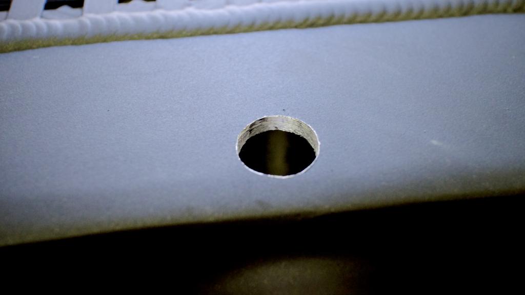
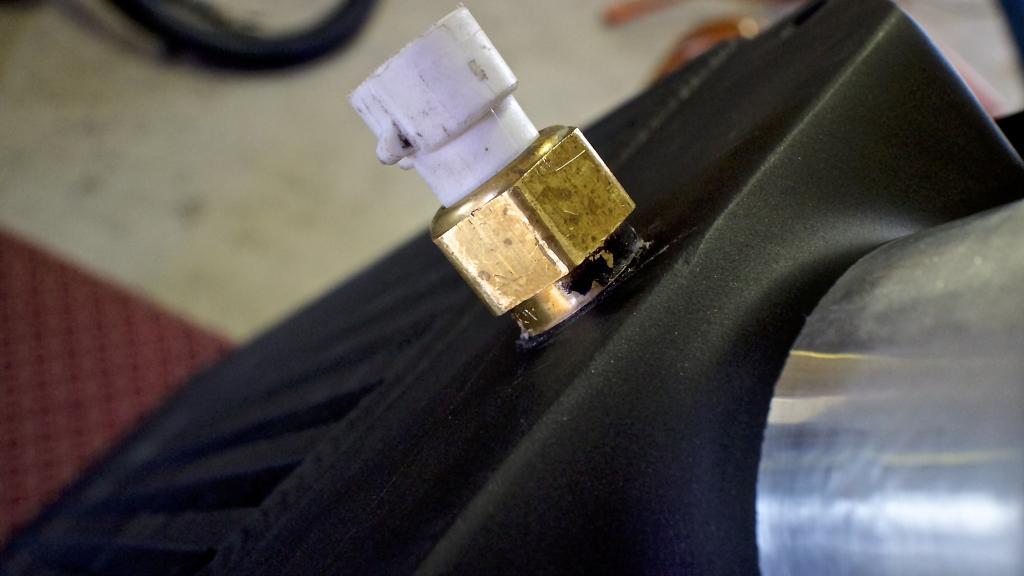
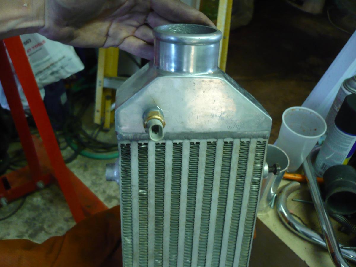
Well, that was a pricy hole. Had to purchase a 9/16 drill bit and a 3/8 NPT tap to install the IAT sensor.
Drill it
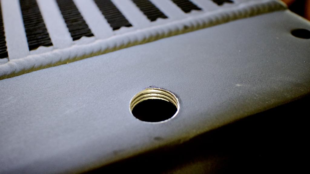
Tap it. I ran the tap and removed it several time to test fit the sensor. I found that 1/2 way down the tap gave it a VERY snug fit...which is what I wanted since the metal isn't thick enough to thread the sensor on all the way.
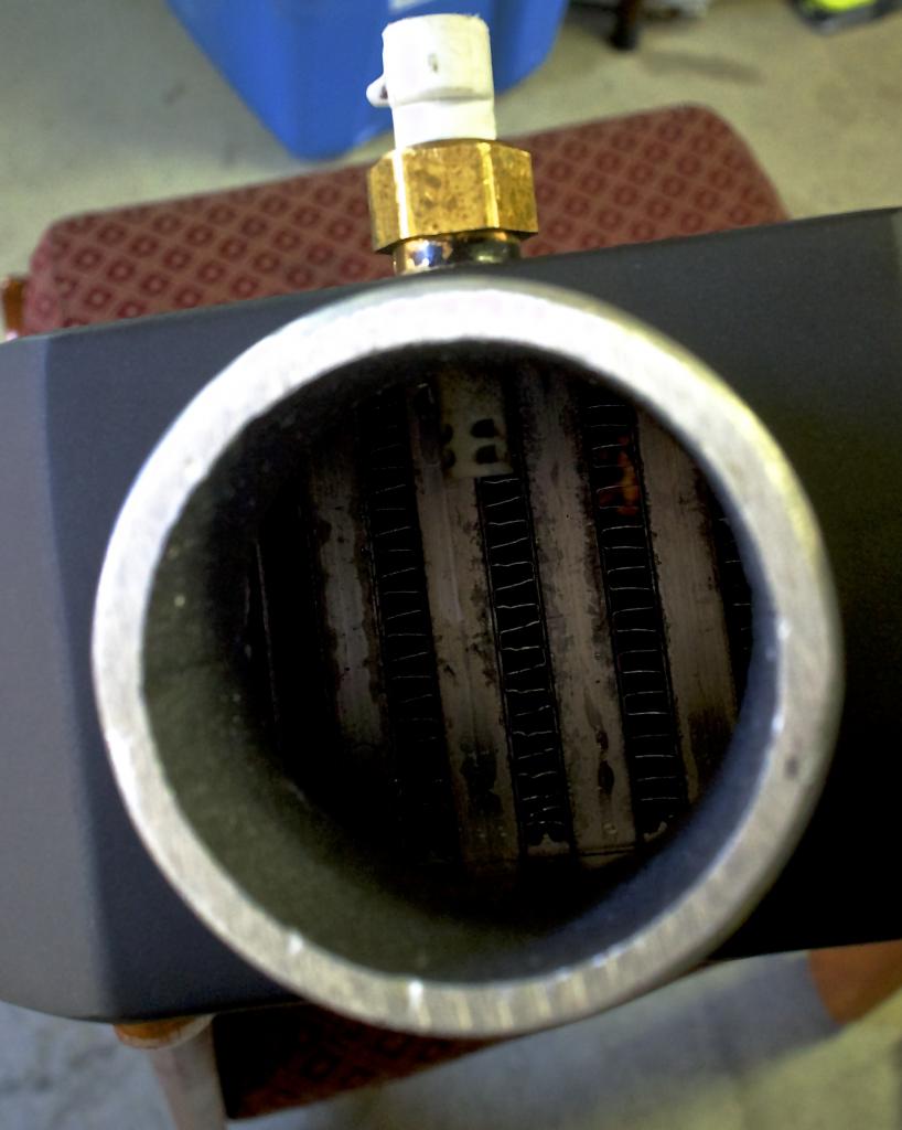
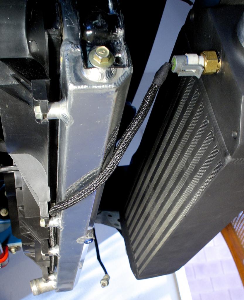
I routed the wires through the headlights, down the side of the radiator, through the fans, and onto the sensor. It really makes it look clean.

Reply
2
2
03-15-2014, 08:56 PM
#1658
Elite Member
Join Date: Oct 2013
Location: Cedar City, UT
Posts: 2,764
Total Cats: 951
I'm talking more baller than I have currently gone!
The picture is misleading, there isn't a flange right there. I basically stopped tightening it when the last of the threads went into the lip of the hole. I only tapped it far enough that the sensor was very tight when tightening it. Plus I put sealant on the threads, it was kind of pointless though since I got it so perfect that it ejected all the sealant as I tightened.
Trust me, it isn't going anywhere.
Trust me, it isn't going anywhere.
Reply
0
0
03-15-2014, 09:24 PM
#1659
Elite Member
iTrader: (13)

Join Date: Dec 2006
Location: Taos, New mexico
Posts: 6,599
Total Cats: 561
IMHO a dab of rtv or jb weld on the threads will make that thing stay forever and seal up. I used JB weld because the IAT sensors are cheap and I had no plans on removing it anytime soon.
Reply
0
0
03-15-2014, 10:06 PM
#1660
Elite Member
Join Date: Oct 2013
Location: Cedar City, UT
Posts: 2,764
Total Cats: 951
Not sure why I didn't use some rtv. I just used some on my reverse sensor on my transmission to hopefully stop the leak.
Reply
0
0


