Ace's Dual Duty LS1 Build


 01-25-2017, 08:10 PM
#42
Senior Member
Thread Starter
iTrader: (1)

Join Date: Dec 2010
Location: Farmington Hills, MI
Posts: 1,218
Total Cats: 175
There are 2 ports on the side of an LS1 water pump. In and out for the heater core, but I am deleting heat. The one pre-thermostat goes to the expansion tank, and the one post-thermostat gets blocked off. I'm putting it in the plug post thermostat.

Reply
 0
0

0
01-29-2017, 07:49 PM
#43
Senior Member
Thread Starter
iTrader: (1)
Join Date: Dec 2010
Location: Farmington Hills, MI
Posts: 1,218
Total Cats: 175
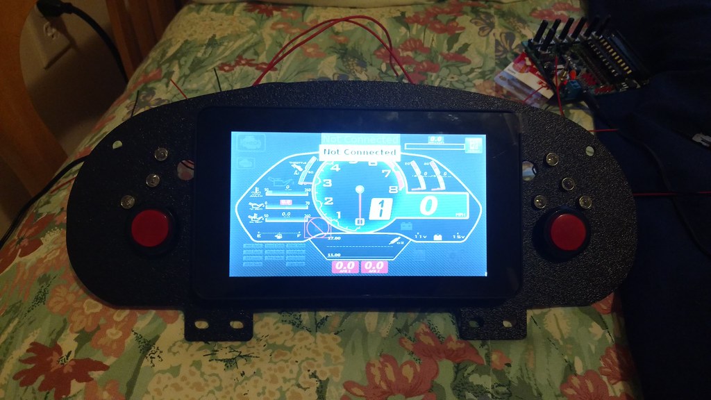
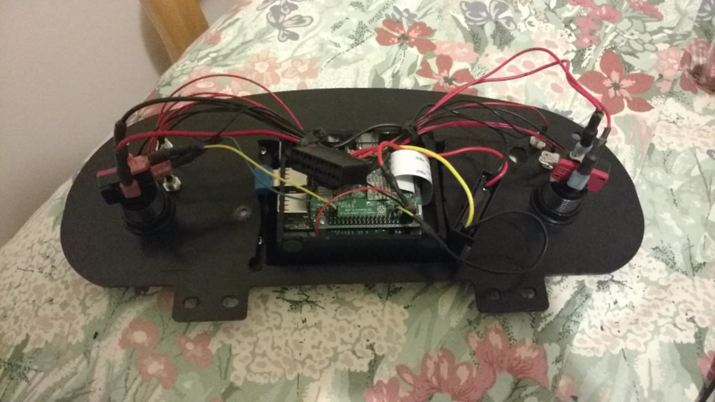
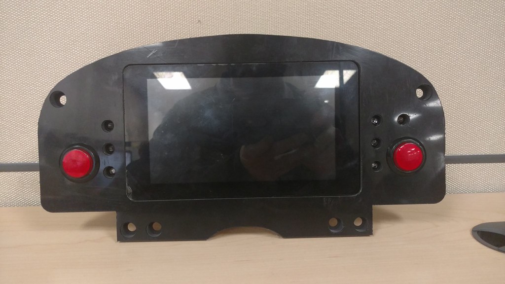
Buttoned up the Raspberry Pi dash. It's a Raspberry Pi 3, 7" Raspberry touchscreen, mounted in a case that's mounted to my cluster plate. It's running Raspbian Jessie and autostarts TunerStudio on startup. I've seen OBDII reading software, so this isn't just for Megasquirt.
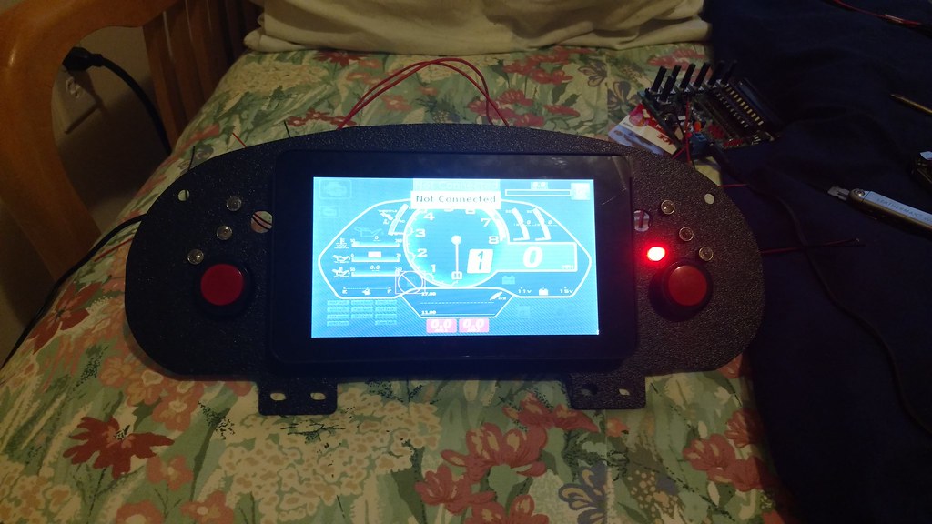
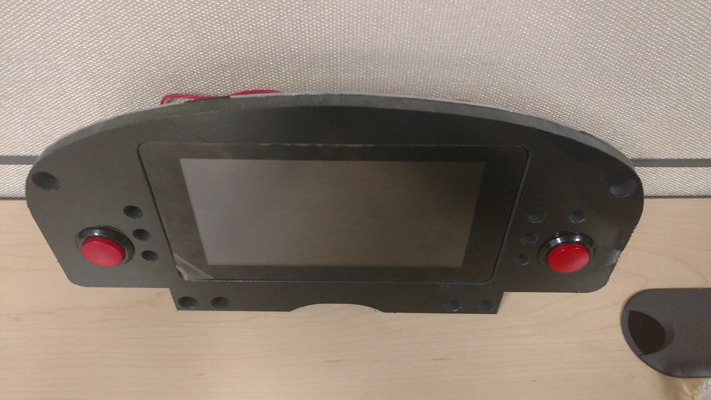
It's powered by a 12-5V 3A regulator from Mausberry Circuits, and has a command that when a GPIO pin is triggered to ground, it commands a safe shutdown. There are switch circuits that are intended to have constant power and switched power, but I just kept it simple. I just have to push the big red button on the right side before killing power to the vehicle. The 3 lights in a row on either side (kind of in a row haha) is a sequential tachometer, so it'll illuminate green, yellow, red as RPM's increase. The red light (shown in the second picture) is a red light for coolant temp warning (just a fail safe in case it's not super easy to see the screen). The big red buttons also have integrated lights, these are the turn signal indicators.
All wiring is crimped and heat shrunk (with glue inside), then terminated to an 8 pin Sumitomo conector (from Corsa Technic) to make it removable from one connector, without pulling any components.
IMG_20170129_172255982 by Adam Watson, on Flickr
IMG_20170129_172227193 by Adam Watson, on Flickr
Snapchat-1522824405 by Adam Watson, on Flickr
Reply
1
1

 01-30-2017, 10:17 PM
#45
Senior Member
Thread Starter
iTrader: (1)
Join Date: Dec 2010
Location: Farmington Hills, MI
Posts: 1,218
Total Cats: 175
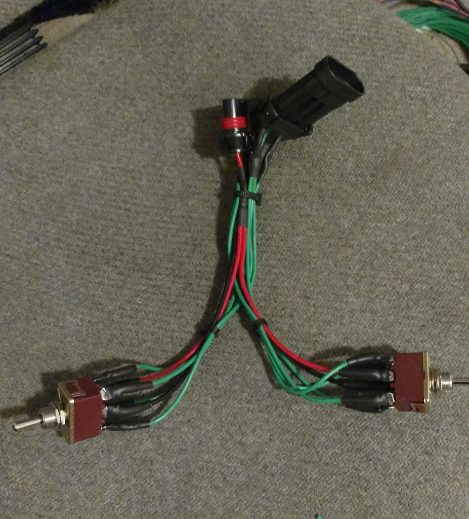
I'm trying to finish up all projects that I can do indoors. I'm really dreading going out to the garage in the cold... I made a little sub-harness for the power window switches that I'm relocating to the center stack area. It took a lot longer than it probably should've.. Everything that may get taken out as an assembly is getting connectors.
IMG_20170130_215548920 by Adam Watson, on Flickr
IMG_20170130_215548920 by Adam Watson, on Flickr
Reply
0
0
01-31-2017, 12:27 AM
#46
Senior Member

Join Date: Jul 2014
Location: Milwaukee, WI
Posts: 1,132
Total Cats: 550
Nice electrical work..
just an idea, it would look damn near factory if you recessed the tablet for the gauges behind the blanking plate instead of on top of it. Regardless, nice work.
just an idea, it would look damn near factory if you recessed the tablet for the gauges behind the blanking plate instead of on top of it. Regardless, nice work.
Reply
0
0
01-31-2017, 08:55 AM
#47
Senior Member
Thread Starter
iTrader: (1)
Join Date: Dec 2010
Location: Farmington Hills, MI
Posts: 1,218
Total Cats: 175
Yeah I was thinking about remounting it like that. If I feel like putting the time into cutting the dash plate nicely so it'll look clean and mounting it properly, I'll probably do that. Thanks!
Reply
0
0
02-04-2017, 07:49 PM
#48
Senior Member
Thread Starter
iTrader: (1)
Join Date: Dec 2010
Location: Farmington Hills, MI
Posts: 1,218
Total Cats: 175
I updated a final version of my center stack switch panel, and brought it to life! The top left and right switches are the power window switches from the previous post. Fighter pilot looking switch is a blower motor switch, followed by the engine start button next to it, then the Accusump activation switch. The 2 USB ports at the top right are just bulkheads, and one will be used for Megasquirt communication. The 2 switches just below are a failsafe for my PWM circuits. I'm PWM'ing both the cooling fan and fuel pump, and if the PWM circuit fails, this will command 100% duty cycle. Button at the bottom is for datalog. The circular E-stop kills power to the ECU and fuel pump. The battery kill is obviously a main kill switch. The two ***** just above control traction control and launch control.
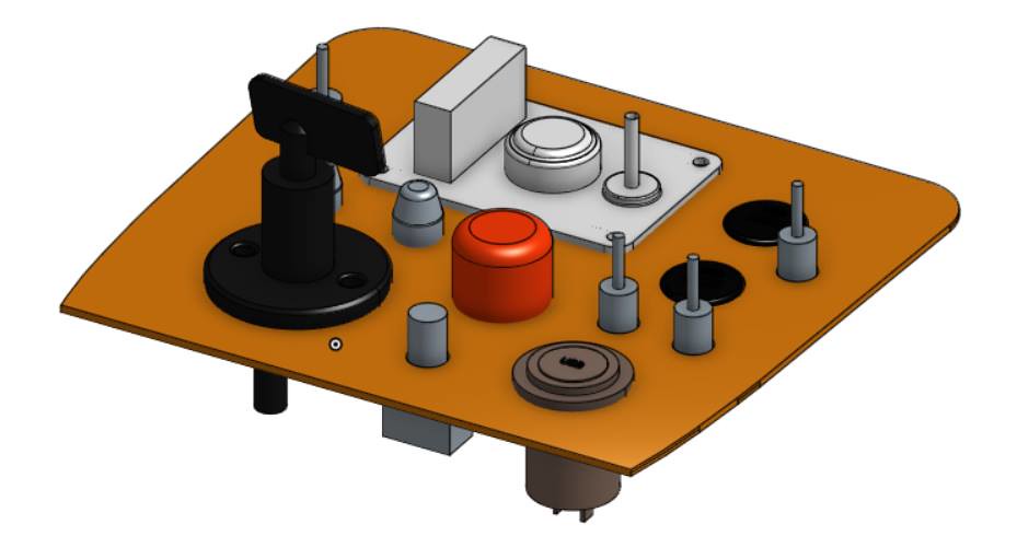
16387010_10155160362883115_8319110369273778173_n by Adam Watson, on Flickr
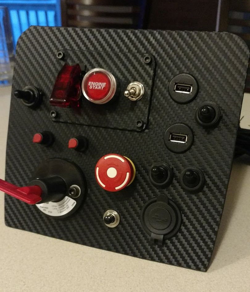
16487711_10155160357548115_7887680035998261698_o by Adam Watson, on Flickr
Reply
3
3
02-07-2017, 02:14 PM
#49
Senior Member
Thread Starter
iTrader: (1)
Join Date: Dec 2010
Location: Farmington Hills, MI
Posts: 1,218
Total Cats: 175
I remade the Raspberry dash plate, it looks 100 times better now. It's a lot heavier than it should be, since I made it on a waterjet. Since it's all 2D machining, and the screen is 0.333" thick, the plate I made it out of had to be 0.375" thick, with a 0.08" backing plate to mount the screen. At least the 0.375" thick piece is HDPE so it's not too heavy, it's actually nice that it feels much sturdier than the Advanced Autosports panel I was previously using. The easy method would be making it on a router so I could take out material. Either way, I'm super happy with how it turned out.
Reply
3
3
02-08-2017, 02:44 PM
#50

looks great
__________________
OG Racing
Your Source For Motorsports Safety Equipment
WWW.OGRACING.COM
800.934.9112
703.430.3303
info@ogracing.com
OG Racing
Your Source For Motorsports Safety Equipment
WWW.OGRACING.COM
800.934.9112
703.430.3303
info@ogracing.com
Reply
0
0


 02-20-2017, 09:16 AM
#54
Senior Member
Thread Starter
iTrader: (1)
Join Date: Dec 2010
Location: Farmington Hills, MI
Posts: 1,218
Total Cats: 175
Test fit the headers with sub-frame. Seems clearances are all good to go. Next step is wrapping the headers. It took a long time to make the decision between coating and wrapping, but I decided that a combination of simplicity of being able to do it myself, cost, and effectiveness, as well as the fact that I really like the look of wrapped headers made it worth it. The trade off is possible corrosion of the headers, but I don't think that'll be an issue with the Kooks stainless. This car will see very minimal rain, so they should stay mostly dry, other than moisture obviously.
Got the clutch and flex plate mounted up! The release bearing is also shimmed to set the clearance between the bearing and the clutch forks. I made a mistake when making my adapter plate for the release bearing, so the fluid ports aren't pointed at the openings on the bellhousing, so now I need 90 degree fittings to get the lines to fit in the bellhousing. Those should be in on Tuesday so I can get the trans on the motor, and get everything installed back in the car to continue accessory mock up and wiring.

Got the clutch and flex plate mounted up! The release bearing is also shimmed to set the clearance between the bearing and the clutch forks. I made a mistake when making my adapter plate for the release bearing, so the fluid ports aren't pointed at the openings on the bellhousing, so now I need 90 degree fittings to get the lines to fit in the bellhousing. Those should be in on Tuesday so I can get the trans on the motor, and get everything installed back in the car to continue accessory mock up and wiring.
Reply
1
1
02-22-2017, 08:15 PM
#55
Senior Member
Thread Starter
iTrader: (1)
Join Date: Dec 2010
Location: Farmington Hills, MI
Posts: 1,218
Total Cats: 175
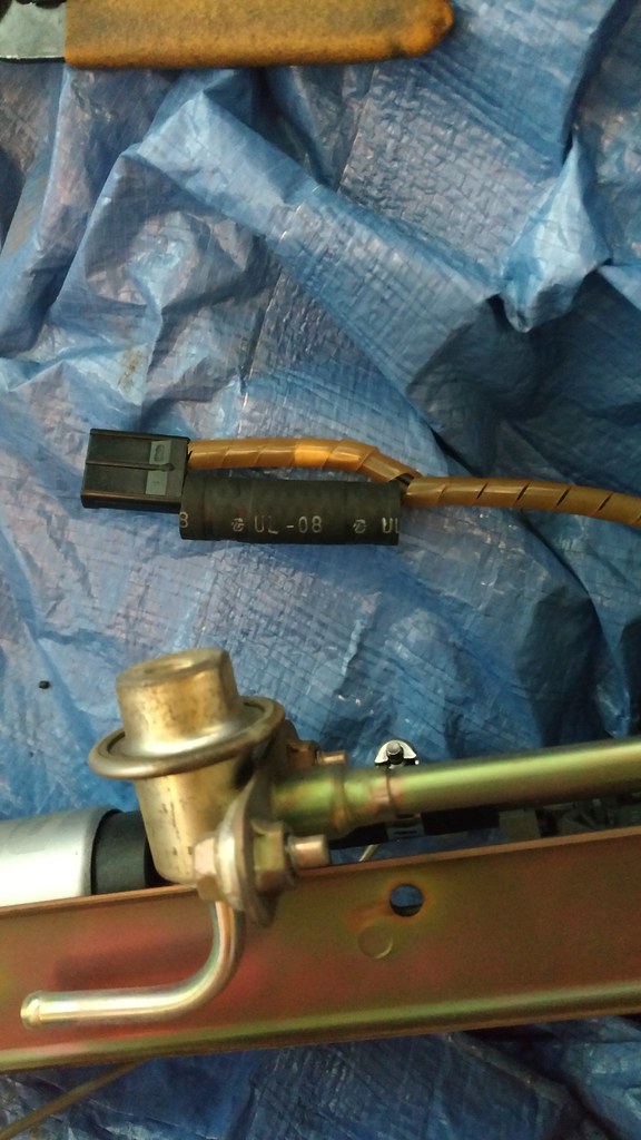
Some small updates. I got the new fuel pump in. I went with a DW300. NB's aren't plug and play for these fuel pumps, so I had to wire in the new connector. I looked all over for how to do the wiring, and came to the conclusion that the wires don't need insulation, just to keep them from touching each other since gasoline is an insulator so it's not conductive. Most heat shrink is not fuel compatible. So I used crimp connections near the fuel pump connector, slid a rubber fuel hose over the splice, then used the factory twisty cord stuff to keep the rubber hose in place, and insulate the ground wire. Before anyone notices, I did remove the regulator that's still on there in the picture.
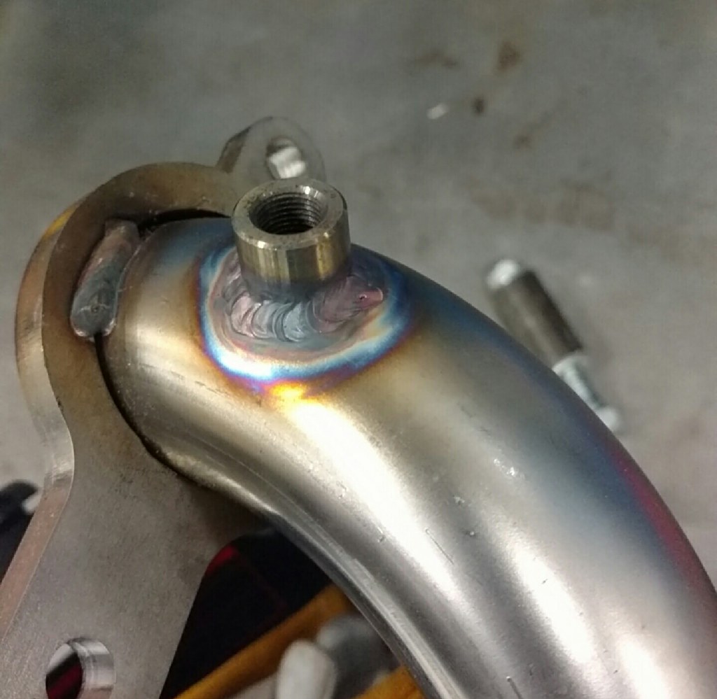
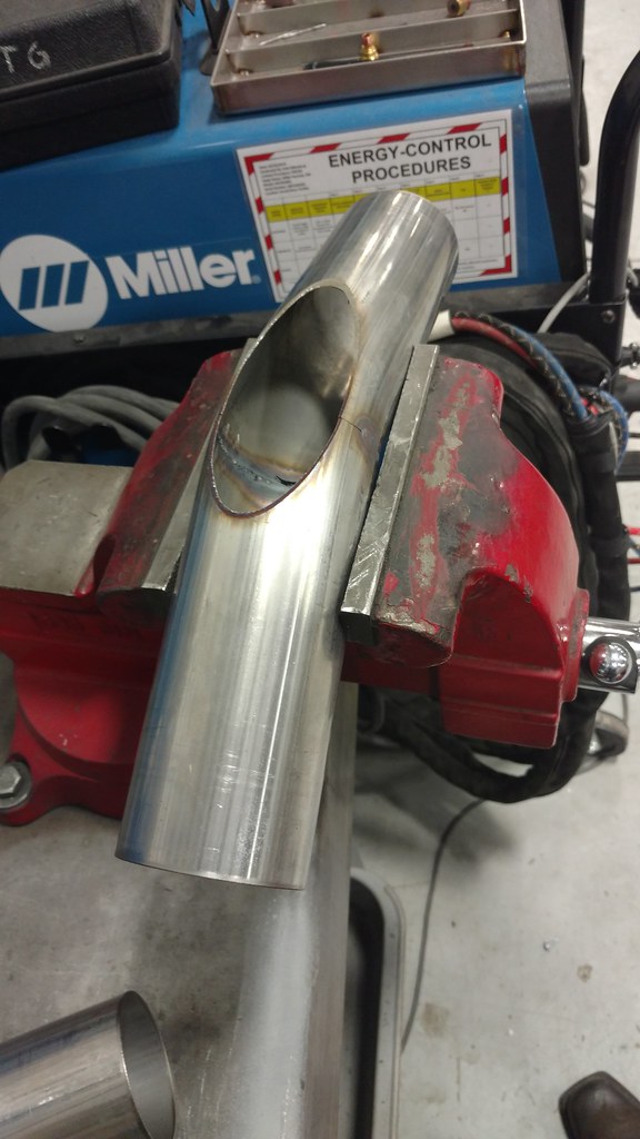
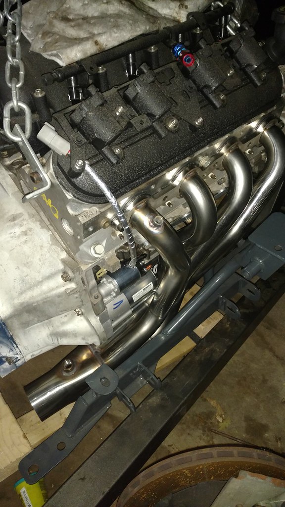
Next up, I welded EGT bungs on the 7th and 8th runners. I'm only using 2 since I'm not trying to do any fancy individual cylinder trims or anything, just monitoring for safety. 7th and 8th runners should be the hottest, and it's probably good to at least see both banks. It's been a few years since I've welded stainless, not too shabby! Makes me excited to make the exhaust.
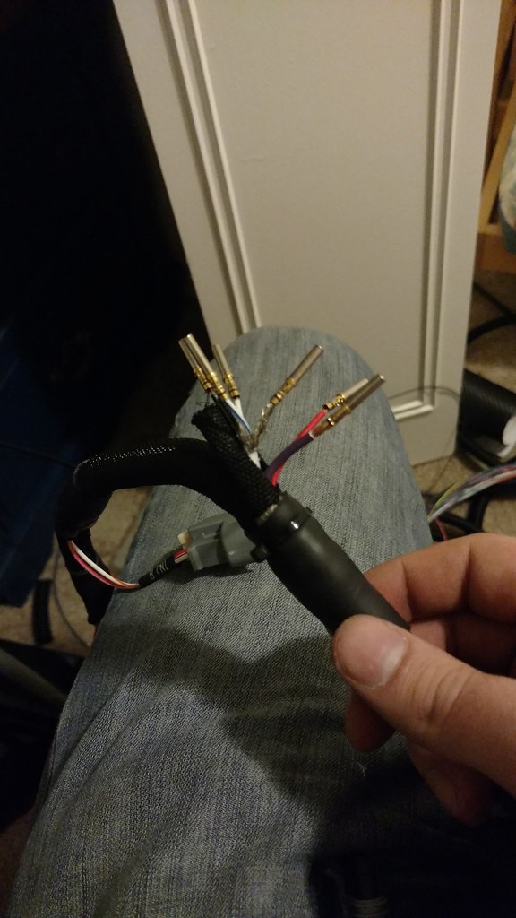
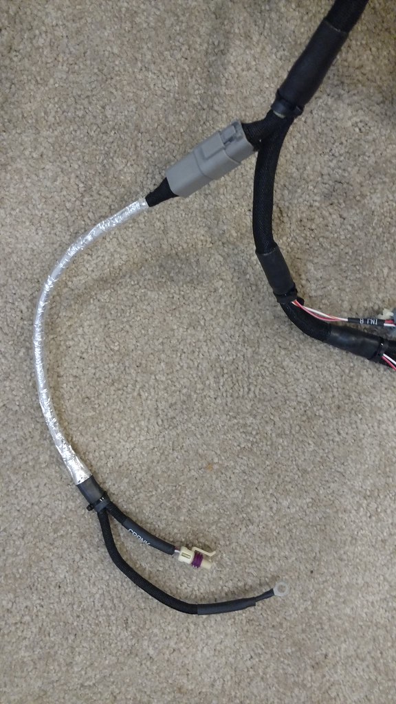
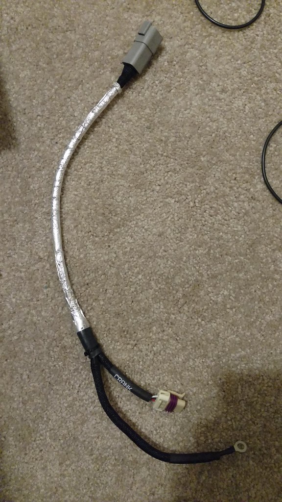
I've always thought it was weird that the crank sensor needs plugged in before the starter can be installed. This would make for an annoying install, that you need to get the motor close to the engine bay, plug in the sensor, install the starter, then install the headers. So I put a Deutsch connector in-line that will sit right at the top of the passenger head. These are solid contacts crimped with a proper DMC crimp tool (the joys of working for a racing company, having nice tools to use!). The crank sensor wire is a shielded wire, so I had to put a pin and socket on the shielding to pass that through the connector.
Next up, I welded EGT bungs on the 7th and 8th runners. I'm only using 2 since I'm not trying to do any fancy individual cylinder trims or anything, just monitoring for safety. 7th and 8th runners should be the hottest, and it's probably good to at least see both banks. It's been a few years since I've welded stainless, not too shabby! Makes me excited to make the exhaust.
I've always thought it was weird that the crank sensor needs plugged in before the starter can be installed. This would make for an annoying install, that you need to get the motor close to the engine bay, plug in the sensor, install the starter, then install the headers. So I put a Deutsch connector in-line that will sit right at the top of the passenger head. These are solid contacts crimped with a proper DMC crimp tool (the joys of working for a racing company, having nice tools to use!). The crank sensor wire is a shielded wire, so I had to put a pin and socket on the shielding to pass that through the connector.
Reply
1
1
02-23-2017, 11:52 AM
#56
cat's given, keep up the good work!
__________________
OG Racing
Your Source For Motorsports Safety Equipment
WWW.OGRACING.COM
800.934.9112
703.430.3303
info@ogracing.com
OG Racing
Your Source For Motorsports Safety Equipment
WWW.OGRACING.COM
800.934.9112
703.430.3303
info@ogracing.com
Reply
0
0
02-23-2017, 10:47 PM
#57
Senior Member
Thread Starter
iTrader: (1)
Join Date: Dec 2010
Location: Farmington Hills, MI
Posts: 1,218
Total Cats: 175
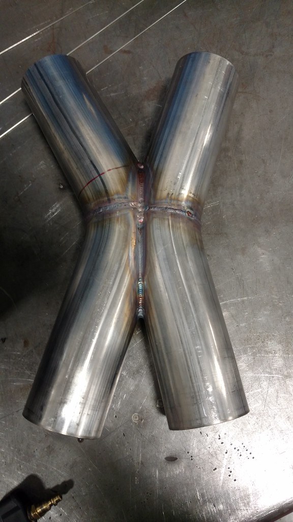
I dug into the scrap pile and found enough bends to make an X-pipe today, even though I won't be using it for a while.
Got the new starter in, it's a truck starter. AC Delco 337-1119 and also ordered the 2 bolts, AC Delco 11610787. This starter is 6.5" from flange to back of the starter, so it has about an inch of clearance to the V8roadsters long tubes. There is only one area where clearance is down to about 0.020", but that's on a little sheet metal piece that houses one of the screws to hold the starter case on. I can grind that down a bit, there's extra meat. You can also see the crank sensor and starter wire in place.
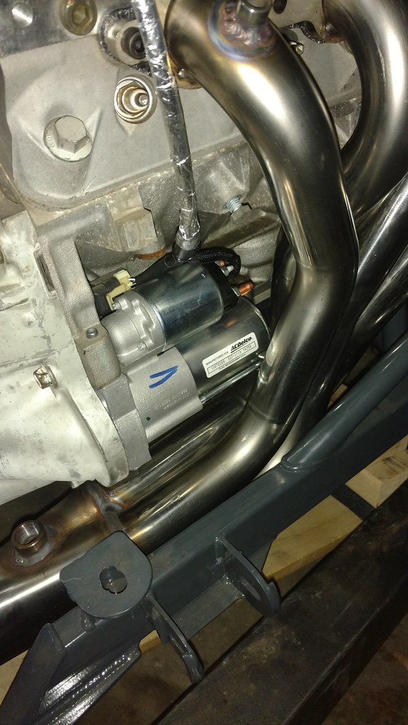
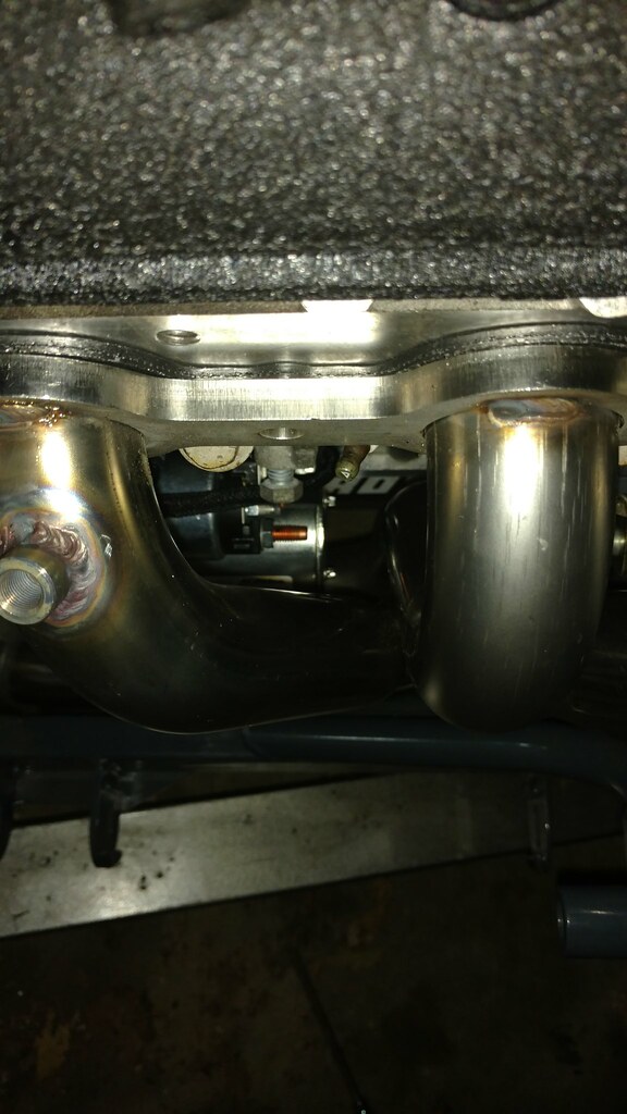
Got the new starter in, it's a truck starter. AC Delco 337-1119 and also ordered the 2 bolts, AC Delco 11610787. This starter is 6.5" from flange to back of the starter, so it has about an inch of clearance to the V8roadsters long tubes. There is only one area where clearance is down to about 0.020", but that's on a little sheet metal piece that houses one of the screws to hold the starter case on. I can grind that down a bit, there's extra meat. You can also see the crank sensor and starter wire in place.
Reply
1
1
02-26-2017, 05:27 PM
#58
Senior Member
Thread Starter
iTrader: (1)
Join Date: Dec 2010
Location: Farmington Hills, MI
Posts: 1,218
Total Cats: 175
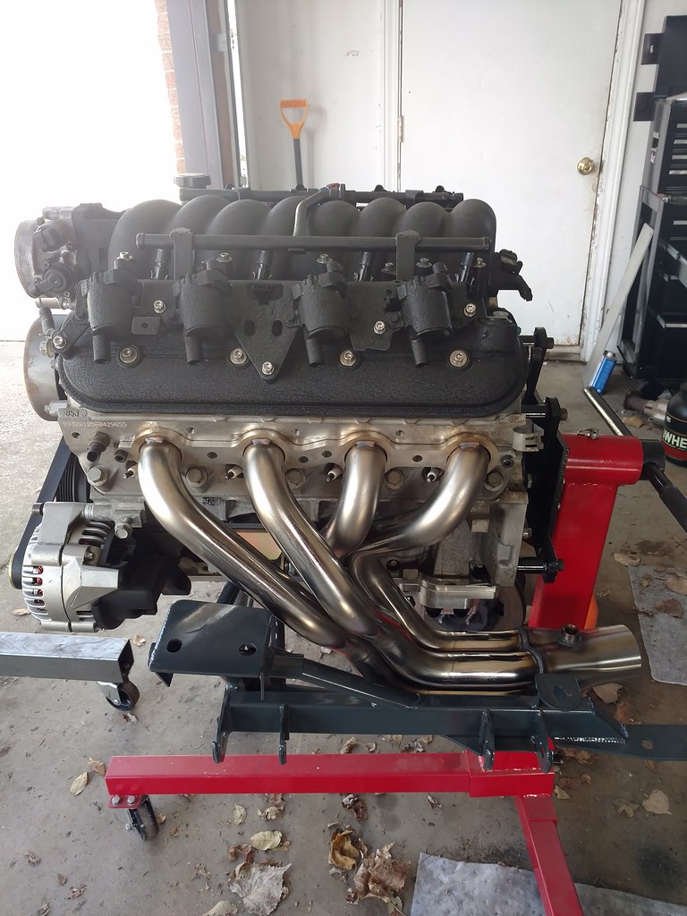
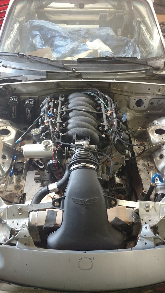
Not as much progress this weekend as I'd like, but it's starting to look like an engine bay at least. I got the engine back in with the headers on so I can start fitting up oil hoses, filter mount, oil cooler, flex fuel sensor, catch cans, etc.
Be warned, V8roadsters long tube headers and the Flyin' Miata LS1 oil pan with remote oil filter mounts are not a good combo. There is VERY little room to work with, and I'm hoping I can find a combination of hose ends that keeps them away from the headers and above the lowest point of the car. I think I have a solution and will post when I have these lines made.
The oil cooler is going to mount perpendicular to the radiator, just to the right of the LS7 intake. I'll have fender vents at some point to expel pressure that builds up in the wheel wells, to help the pressure differential over the oil cooler, but there's going to be a huge high pressure zone in front of it anyway. Then the filter will mount near where it is in the picture, but the filter will hang inboard of the frame rail.
I've also got some coolant hoses that work. I picked up hoses E71317 and E72044. These match the diameters of the radiator and LS1 ports. My Sirocco radiator has 1.5" and 1.75" ports whereas the LS1 has 1.25" and 1.5" ports, and these hoses have the appropriate reduction built in. I'm just taking the 90 degree bends from the ends of each of these hoses, and using a coupler in between.
Also got the Diyautotune plug and play harness test fit on there, and started wiring up the LS7 MAF, since the harness doesn't use MAF and uses an LS1 IAT.
Reply
1
1
02-27-2017, 11:02 AM
#59
where do you guys get these ls1 expansion tanks? i want one of those.
__________________
OG Racing
Your Source For Motorsports Safety Equipment
WWW.OGRACING.COM
800.934.9112
703.430.3303
info@ogracing.com
OG Racing
Your Source For Motorsports Safety Equipment
WWW.OGRACING.COM
800.934.9112
703.430.3303
info@ogracing.com
Reply
0
0
02-27-2017, 11:45 AM
#60
Senior Member
Thread Starter
iTrader: (1)
Join Date: Dec 2010
Location: Farmington Hills, MI
Posts: 1,218
Total Cats: 175
https://www.summitracing.com/parts/HRE-3424
I just took a piece of 1/8" aluminum and drilled the holes for the tapped holes in the head. Then Welded that plate tangent to the expansion tank. Then welded a little gusset in the middle to support from bending.
I just took a piece of 1/8" aluminum and drilled the holes for the tapped holes in the head. Then Welded that plate tangent to the expansion tank. Then welded a little gusset in the middle to support from bending.
Reply
1
1


