AlexL's 91 1.6 Greddy MS1 Build

 02-26-2013, 09:35 AM
#22
Boost Czar


iTrader: (62)
Join Date: May 2005
Location: Chantilly, VA
Posts: 79,493
Total Cats: 4,080
That's not a method I ever recommend anymore.
There's still no need to pull the fuse unless you have a MSPNP or your MS was built using a high-side driver circuit like the MSPNP.
I don't build that and my solution requires the user to jump two pins in the AFM connector. the end.
There's still no need to pull the fuse unless you have a MSPNP or your MS was built using a high-side driver circuit like the MSPNP.
I don't build that and my solution requires the user to jump two pins in the AFM connector. the end.

Reply
 0
0

0
02-26-2013, 09:43 AM
#23
Junior Member
Thread Starter

Join Date: Oct 2009
Location: Stamford, CT
Posts: 212
Total Cats: 3
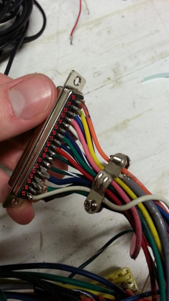
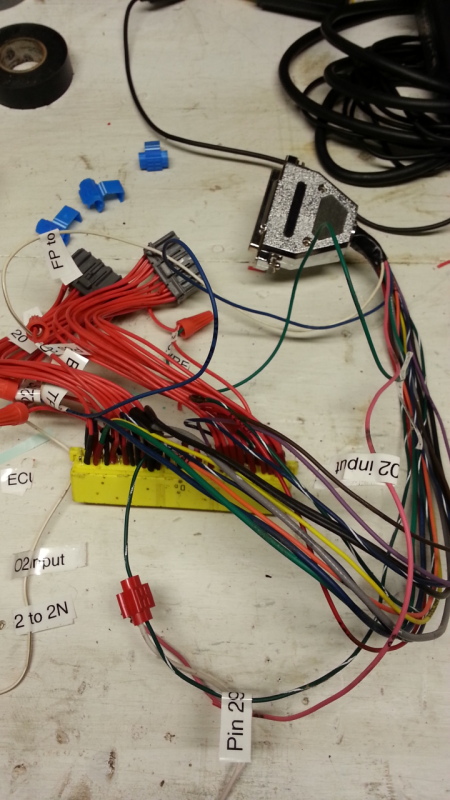
I at least found the fuel pump wire on pin 37. It's gray and it runs to the black wire, not the long white wire as previously thought (I think my long white wire runs to pin 29 which is fans?).
Pink still looks to be wbO2 which is on Pin 23. This goes directly to the db37 connector because the stock ecu doesn't know to expect a wideband o2 signal, right? And then I run my narrowband output from my wideband to the short white wire spliced in my harness I guess.
Although I don't see a spot for the oem o2 signal in here:
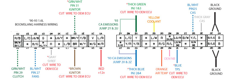
Ok so I opened up my db37 connector and just when I thought I was understanding things I am confused again. I know the position is important, not the color. Since the diagrams for the db37 only have color it is hard to trace them back to my incorrectly colored harness. So I'm looking for 5VREF since the blue TPS wire on pin 22 looks correct, apparently spliced into the harness to accept the signal from the stock TPS. The 5VREF wire on pin 26 which is supposed to be gray is green, and it's labeled F-Idle, and it's spliced into the stock harness (why?) since I don't know what the stock ECU is going to do with a variable TPS signal. Seems like I should just cut that wire too. Maybe this will make more sense when I look at my oem wiring.
Pink still looks to be wbO2 which is on Pin 23. This goes directly to the db37 connector because the stock ecu doesn't know to expect a wideband o2 signal, right? And then I run my narrowband output from my wideband to the short white wire spliced in my harness I guess.
Although I don't see a spot for the oem o2 signal in here:
Ok so I opened up my db37 connector and just when I thought I was understanding things I am confused again. I know the position is important, not the color. Since the diagrams for the db37 only have color it is hard to trace them back to my incorrectly colored harness. So I'm looking for 5VREF since the blue TPS wire on pin 22 looks correct, apparently spliced into the harness to accept the signal from the stock TPS. The 5VREF wire on pin 26 which is supposed to be gray is green, and it's labeled F-Idle, and it's spliced into the stock harness (why?) since I don't know what the stock ECU is going to do with a variable TPS signal. Seems like I should just cut that wire too. Maybe this will make more sense when I look at my oem wiring.
Reply
0
0
02-26-2013, 09:59 AM
#24
Boost Czar
iTrader: (62)
Join Date: May 2005
Location: Chantilly, VA
Posts: 79,493
Total Cats: 4,080
Pink still looks to be wbO2 which is on Pin 23. This goes directly to the db37 connector because the stock ecu doesn't know to expect a wideband o2 signal, right? And then I run my narrowband output from my wideband to the short white wire spliced in my harness I guess.
Although I don't see a spot for the oem o2 signal in here:
Although I don't see a spot for the oem o2 signal in here:
So I'm looking for 5VREF since the blue TPS wire on pin 22 looks correct, apparently spliced into the harness to accept the signal from the stock TPS.
The 5VREF wire on pin 26 which is supposed to be gray is green, and it's labeled F-Idle, and it's spliced into the stock harness (why?) since I don't know what the stock ECU is going to do with a variable TPS signal. Seems like I should just cut that wire too. Maybe this will make more sense when I look at my oem wiring.
The 5VREF wire on pin 26 which is supposed to be gray is green, and it's labeled F-Idle, and it's spliced into the stock harness (why?) since I don't know what the stock ECU is going to do with a variable TPS signal. Seems like I should just cut that wire too. Maybe this will make more sense when I look at my oem wiring.
The unit doesnt have the idle control wire attached on pin 30 because, again, the unit was built for a piggyback setup and therefore the stock ECU controlled the idle.
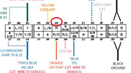
If you want to run the fuel pump, connect the wire on pin37 to 2O. then jump the two pins in the AFM connector.
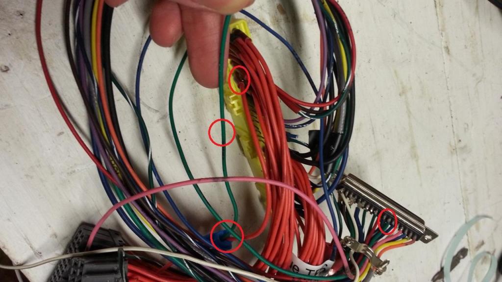
Please stop referencing old-outdated, bad-practices, charts/info and just ask here. A lot of MSI information out there should be purged in a great big bonfire. Also please stop circle random colored wires and spots on the harness. I need exact positions to help you out. (e.g. Pin37 is unattached, but pin 36 goes to 1H.)
Reply
0
0
02-26-2013, 10:14 AM
#25
Junior Member
Thread Starter
Join Date: Oct 2009
Location: Stamford, CT
Posts: 212
Total Cats: 3
Thanks, I really do appreciate it. Sorry for trying to MS Paint the questions here. Brain, would it be possible to build a fresh db37 and harness for me? Can I PM you about such a service? I'm almost ready to just get an MS3, almost.
Reply
0
0
 02-26-2013, 11:37 AM
#27
Junior Member
Thread Starter
Join Date: Oct 2009
Location: Stamford, CT
Posts: 212
Total Cats: 3
it's possible this unit was prewired for a vTPS (not sure why the green wire). Otherwise the stock TPS is unusable. You need to figure out exactly where the Blue wire and Green wire go on the harness. If the green wire goes to pin 1N, then you must unplug the stock TPS connector until you upgrade to a vTPS, else it will cause a fault and the MS will not connect/run.
Ok I'll take another look tonight
Reply
0
0
02-26-2013, 11:46 AM
#28
Boost Czar
iTrader: (62)
Join Date: May 2005
Location: Chantilly, VA
Posts: 79,493
Total Cats: 4,080
correct.
yes you'd want to cut the wire back to the stock ECU (are you even going to use the stock ECU?) because that's normally the 5v output from the ECU to power the AFM.
do you understand what that means? the wire should go from the MS to the oem wiring, but not be touched by the oem ECU, so the red wire in the harness connecting those should be severed. you'll see this on pins 2U and 2V for example.
Reply
1
1
02-26-2013, 11:59 AM
#31
Junior Member
Thread Starter
Join Date: Oct 2009
Location: Stamford, CT
Posts: 212
Total Cats: 3
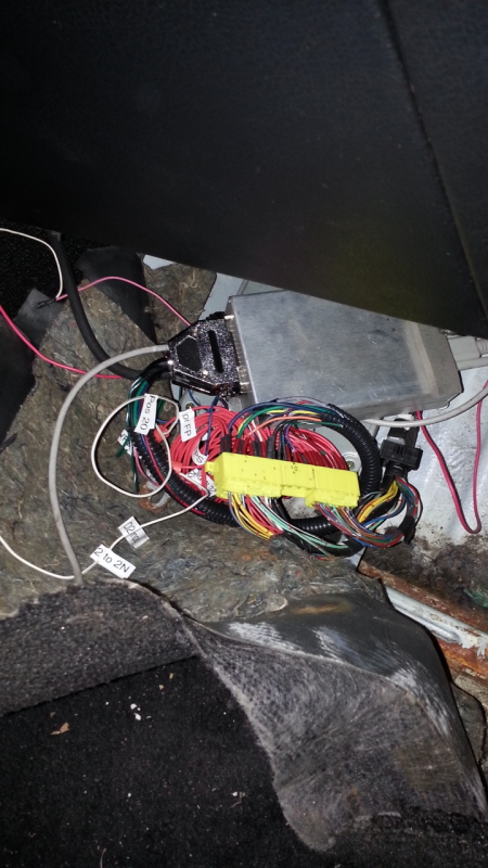
Yes, wire will go from yellow connector back to db37. Never goes to the plugs that send everything else back to the ecu. It's funny that there are so many wires going back to the ecu but it's doing almost nothing.
Reply
0
0
 03-19-2013, 11:38 AM
#34
Junior Member
Thread Starter
Join Date: Oct 2009
Location: Stamford, CT
Posts: 212
Total Cats: 3
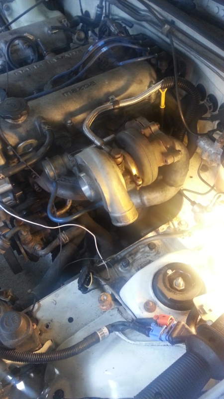
Made some progress despite it being 36 degrees in my garage.
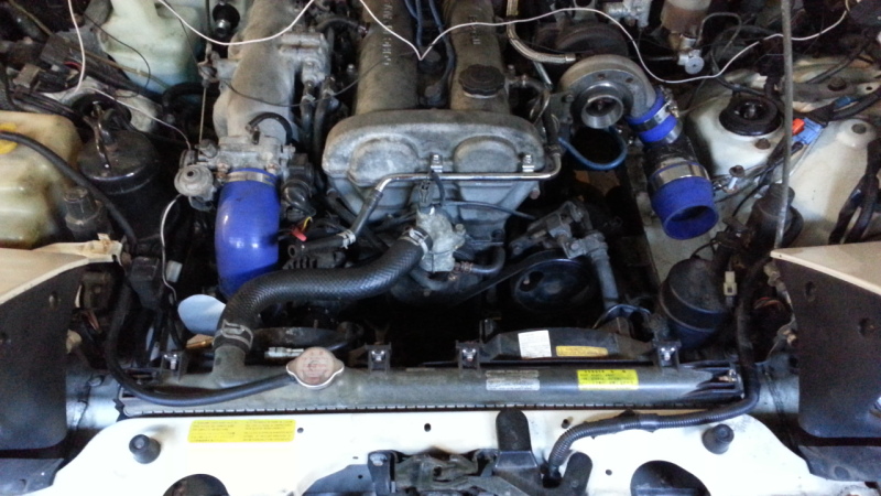
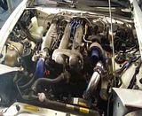
Turbo and downpipe Mounted:
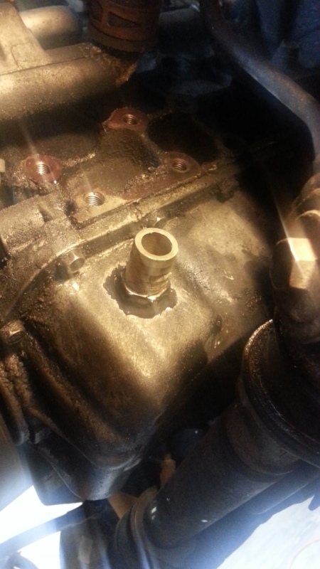
Oil pan drilled and tapped:
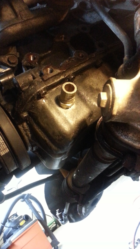
JB Weld:
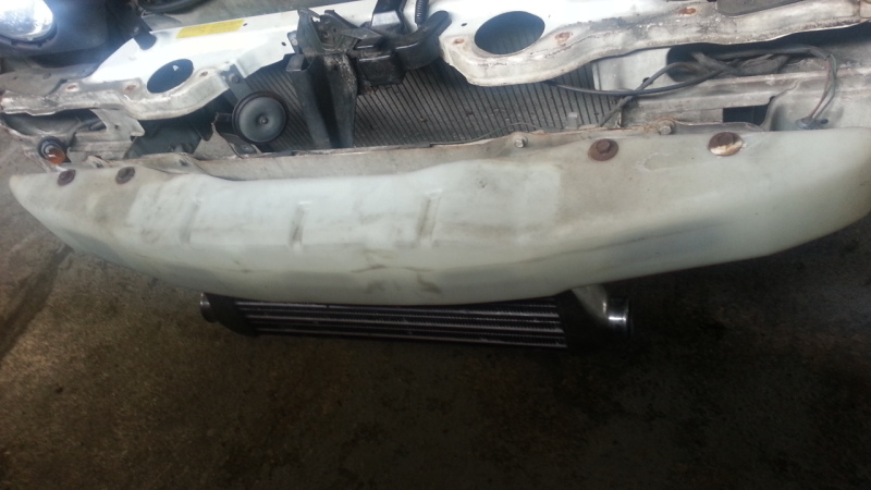
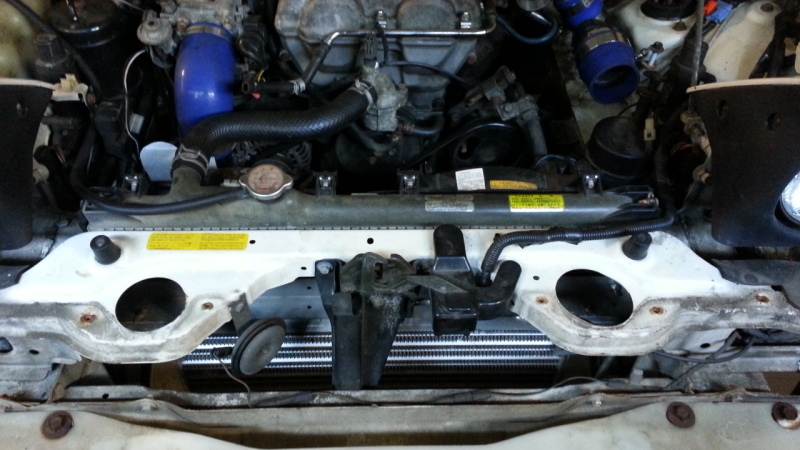
The intercooler bolted here perfectly but of course the bumper won't fit. I think I may move it closer to the radiator and do some duct work.
Turbo and downpipe Mounted:
Oil pan drilled and tapped:
JB Weld:
The intercooler bolted here perfectly but of course the bumper won't fit. I think I may move it closer to the radiator and do some duct work.
Reply
0
0
 04-16-2013, 10:23 AM
#36
Junior Member
Thread Starter
Join Date: Oct 2009
Location: Stamford, CT
Posts: 212
Total Cats: 3
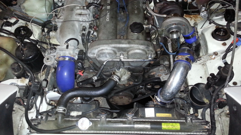
Piping done:
The Cluster F that is my wiring right now. Have to trim my boost gauge line so I'm not just shoving it under the dash.
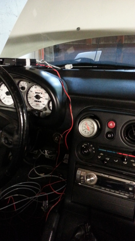
My Boost gauge is kind of haphazardly in the eyeball vent, have to get some better fitment. Things left to do: Bleed my clutch, plug in the MS, and clean up some wiring. Then I'll be ready to start the car.
Reply
0
0
04-19-2013, 08:41 AM
#37
Junior Member
Thread Starter
Join Date: Oct 2009
Location: Stamford, CT
Posts: 212
Total Cats: 3
Did this on Thursday:
Then last night I calibrated my TPS, which of course was wired backwards. Primed the engine with cranking. Flashed the firmware with my ignitor unplugged. Pulled the tune from the MS and started her up! Click for video.
I still need to wire in some capacitors for the narrowband output to the stock ECU and the wideband output to the MS but otherwise it seems to be running pretty decent. I'm using an 8 year old PLX M300 because it's simple and combines the controller and gauge into one piece. The car is still on stands but hopefully this weekend I can start tuning.
Reply
0
0
04-28-2013, 05:10 PM
#38
Junior Member
Thread Starter
Join Date: Oct 2009
Location: Stamford, CT
Posts: 212
Total Cats: 3
Ok I finally got out to do some tuning today. I set the timing which made the idle nice and smooth and went for a cruise.
At first with the map that was loaded from the previous owner (92Redturbomiata) the car was running great, 14:1 AFRs in cruise, nice and rich in boost (11's right now). I did some auto-tuning, everything is fine. Then I pull over to check my oil lines (the Greddy turbo is still giving me wisps of smoke despite a nice and big and direct return line). When I started the car back up it was running super lean. Like 17's in cruise, 14's in boost.
I'm only going to 1-2 psi right now since I'm paranoid. Then the car is barely idling at like 18:1. So I bring the car home, adjust the idle by hand a little, then take the car out for an auto-tune. It immediately starts richening up my whole table because the car was running super lean. Now it's running better but I'm wondering why all of a sudden my whole fuel map is lean. In a bizarre coincidence my check engine light which was on (I thought was for the narrowband o2 signal even though that is hooked up, but I never pulled the code since the ECU is doing almost nothing) is now off.
I've attached a log and my tune, which was my first time so I hope I did it right. Maybe my stock fuel pump is giving up or something? Oh well, no harm but I'm just a little concerned, and confused. Thanks for the help!
Reply
0
0
04-28-2013, 08:48 PM
#39
if it was giving you burst of smoke it might have caught some on the o2, might clean it and try again. thats weird that its smoking a bit, i never had a problem from it even with it draining to the passenger side nipple. ill look at the MSQ and Log later to see if i noticed anything.
Reply
0
0
04-29-2013, 11:03 AM
#40
Junior Member
Thread Starter
Join Date: Oct 2009
Location: Stamford, CT
Posts: 212
Total Cats: 3
It's not smoking a lot. I have a wicked exhaust leak where my cat gasket cracked. If you stare at the downpipe you can just see, and smell, a hint of smoke when it's idling. I swapped the return line twice I was so paranoid but the current line is 3/4" and straight down. If the turbo is smoking at this point, it has to be the turbo seals. I also smell oil burning when I rev the car up and hit just a little boost. I'm running dino oil right now to clean out the shavings from drilling the pan. I plan on dumping the oil soon, so we'll see.
I'm more confused about why my whole fuel map is lean now. Unfortunately I only get to drive the car on the weekends as I don't feel comfortable commuting in traffic with it yet. It's a shame too because when I first took it out it was idling great and boosting nice and safely.
I'm more confused about why my whole fuel map is lean now. Unfortunately I only get to drive the car on the weekends as I don't feel comfortable commuting in traffic with it yet. It's a shame too because when I first took it out it was idling great and boosting nice and safely.
Reply
0
0


