BEAVIS' White NB Turbo Track Car
 08-31-2016, 02:39 AM
#42
Junior Member
Thread Starter

Join Date: Mar 2011
Location: Melbourne, Australia
Posts: 212
Total Cats: 66
While a large majority of the underbonnet work on the car is done (well, for now), there were a couple of things that I did need to address to settle my OCD.
So, I wanted to moved the IAT sensor to read post intercooler.
The easiest way to do this was to tap into the side of the intercooler. I'm hoping that where the sensor is now mounted will give a reasonably accurate reading.
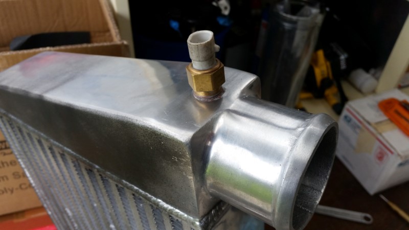
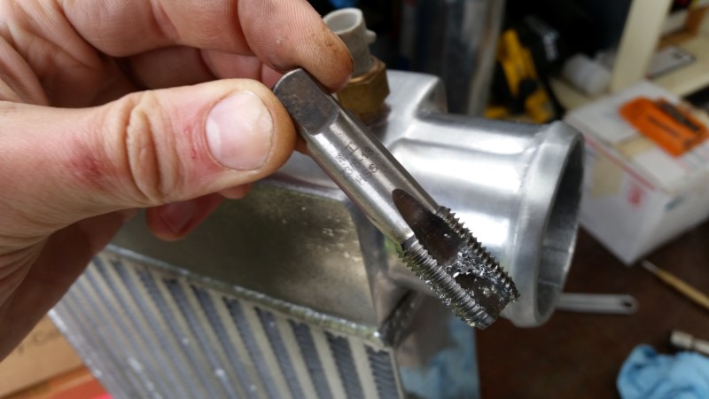
The standard GM IAT calls for a 3/8 NPT Tap....
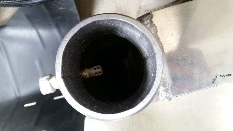
Here's a shot down into the gizzards of the cooler. It all looks about right to me.
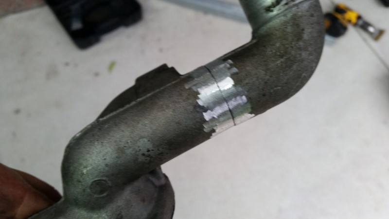
The other thing that needed attention was the water pump inlet pipe. It was too close to the turbo for my liking, and meant that removing the turbo would probably require removing this pipe.
So I took to it with the cutting blade on the grinder, and gave it a slight kink, just enough to get the clearance I need.
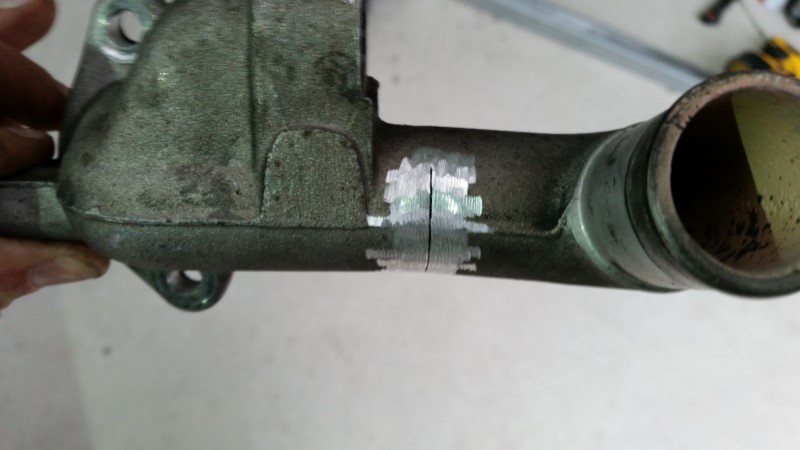
Next is to weld this back together, but I'll leave that for another day.
So, I wanted to moved the IAT sensor to read post intercooler.
The easiest way to do this was to tap into the side of the intercooler. I'm hoping that where the sensor is now mounted will give a reasonably accurate reading.
The standard GM IAT calls for a 3/8 NPT Tap....
Here's a shot down into the gizzards of the cooler. It all looks about right to me.
The other thing that needed attention was the water pump inlet pipe. It was too close to the turbo for my liking, and meant that removing the turbo would probably require removing this pipe.
So I took to it with the cutting blade on the grinder, and gave it a slight kink, just enough to get the clearance I need.
Next is to weld this back together, but I'll leave that for another day.

Reply
 0
0

0
09-12-2016, 08:05 AM
#43
Junior Member
Thread Starter
Join Date: Mar 2011
Location: Melbourne, Australia
Posts: 212
Total Cats: 66
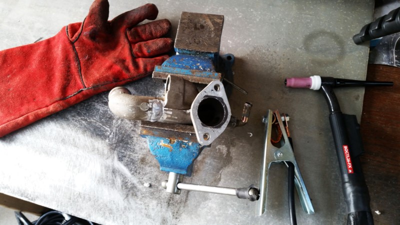
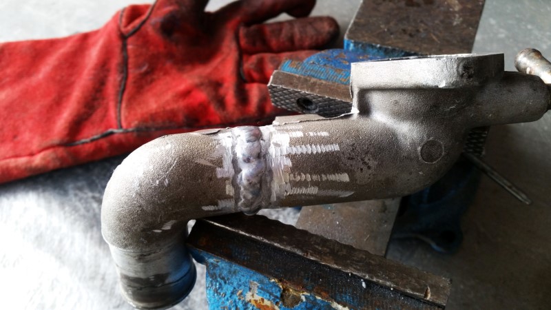
Here's the result of my first aluminium weld attempt - welding the water pump coolant inlet pipe as mentioned in the last post.
Not great, not a disaster and not bad for a first try I guess. But, most importantly, water tight. And now it offers the extra clearance from the turbo inlet which is what I was after.
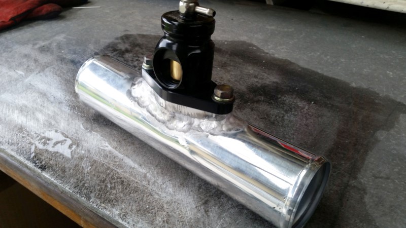
And while I was at it, I had a go at welding the BOV flange to this aluminium intake tube. This is the tube that runs between the intercooler and the throttle body.
I cut, drilled and opened up a hole in the tube to allow the flange to receive the air, then massaged it to try ensure the tube and the flange meet up reasonably close. There were a few large gaps that made welding trickier. I think the differences in thickness also made it trickier. Being a polished pipe, there's probably a heap of polishing compound in there causing contamination?
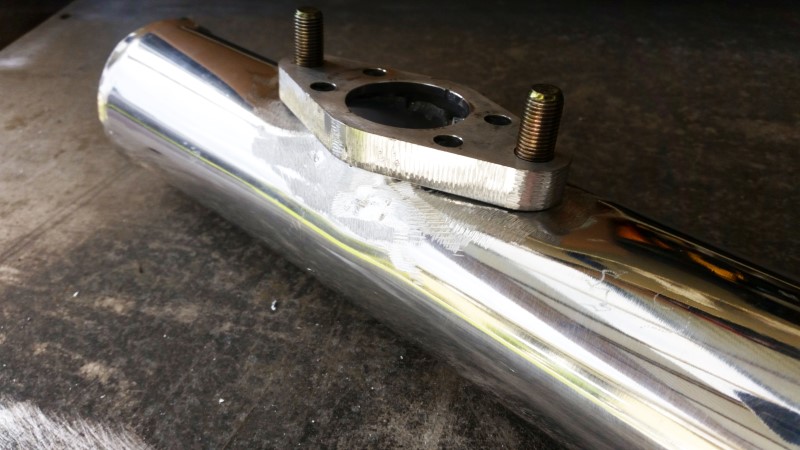
The BOV in question is a turbosmart kompact for a Nissan I believe. Although it's a 'plumback' design, I'm just going to run it open to atmosphere as pictured.
Not great, not a disaster and not bad for a first try I guess. But, most importantly, water tight. And now it offers the extra clearance from the turbo inlet which is what I was after.
And while I was at it, I had a go at welding the BOV flange to this aluminium intake tube. This is the tube that runs between the intercooler and the throttle body.
I cut, drilled and opened up a hole in the tube to allow the flange to receive the air, then massaged it to try ensure the tube and the flange meet up reasonably close. There were a few large gaps that made welding trickier. I think the differences in thickness also made it trickier. Being a polished pipe, there's probably a heap of polishing compound in there causing contamination?
The BOV in question is a turbosmart kompact for a Nissan I believe. Although it's a 'plumback' design, I'm just going to run it open to atmosphere as pictured.
Reply
0
0

 09-14-2016, 04:39 AM
#46
Junior Member
Thread Starter
Join Date: Mar 2011
Location: Melbourne, Australia
Posts: 212
Total Cats: 66
Mounting the IAT where I did was a nice, solid and convenient location, and I can route the wiring there neatly.
The key thing is to get the IAT mounted AFTER the intercooler has done it's job.
I highly doubt there will be more than a degree or 2 of air temperature difference in the 250mm of straight aluminium tube from the intercooler to the throttle body.
The key thing is to get the IAT mounted AFTER the intercooler has done it's job.
I highly doubt there will be more than a degree or 2 of air temperature difference in the 250mm of straight aluminium tube from the intercooler to the throttle body.
Reply
0
0
 09-15-2016, 08:11 AM
#50
Junior Member
Thread Starter
Join Date: Mar 2011
Location: Melbourne, Australia
Posts: 212
Total Cats: 66
I actually didn't really consider it that much, my thought process was more along the lines of 'eh this seems like a good spot for it'... In hindsight, I'm happy with my intuition on this one.
Reply
0
0
09-18-2016, 01:47 AM
#51
Junior Member
Thread Starter
Join Date: Mar 2011
Location: Melbourne, Australia
Posts: 212
Total Cats: 66
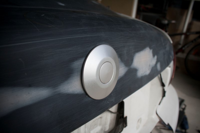
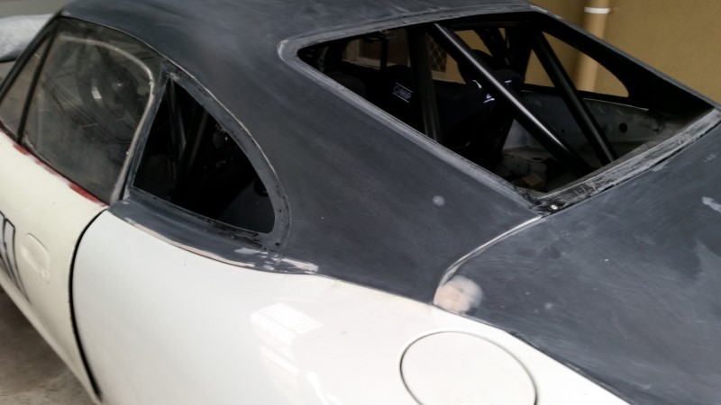
A couple of weeks ago I spent a weekend making these new flat carbon/fibreglass door trims to replace the previous CF ones which were too bulky for these gutted doors.
I wanted a simple flat panel, with a neat door pull and opener. The previous door trim opener was just a bit of electrician wire, and there was no door pull at all. So pretty much anything was better than what I had before.
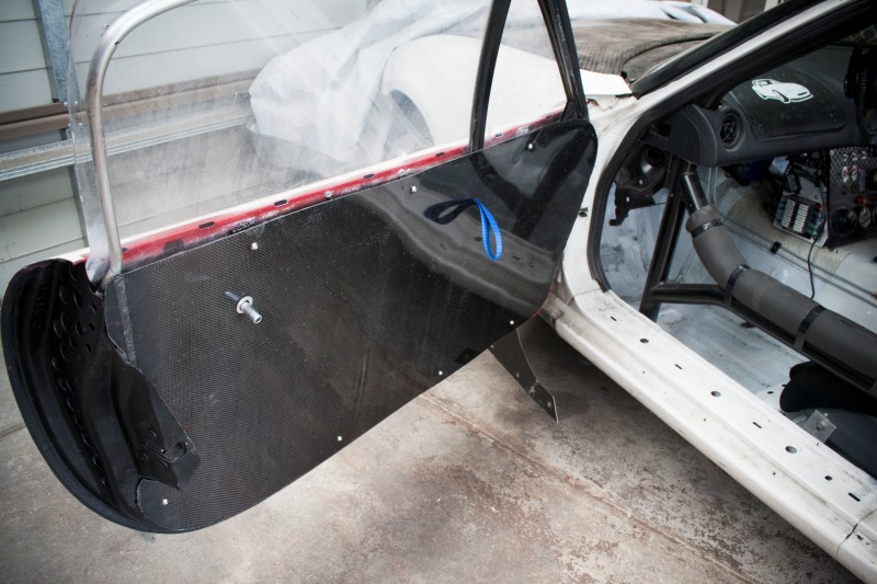
The trim is mounted with 7 hex head M6 bolts. I riveted on these aluminium tabs and threw a rivnut in them
The interior door handle you may have noticed in the first pic is simply some aluminum tube bolted to the inner side of the exterior door handle. Pushing on the tube from inside the car will push the exterior door handle out. But, its simple and no fancy/complicated latch mechanisms required. Hand looks far too dirty for an IT nerd.
I'll finish off the top edge that meets the window with some sort of trim - haven't worked that out yet.
The door pulls were some random blue strap I had lying around. Opening the door is now as easy as pushing your thumb on the alloy tube and out the door pops.
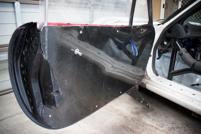
Next thing on the to-do list is to start on sanding and painting the new fastback roof...
I wanted a simple flat panel, with a neat door pull and opener. The previous door trim opener was just a bit of electrician wire, and there was no door pull at all. So pretty much anything was better than what I had before.
The trim is mounted with 7 hex head M6 bolts. I riveted on these aluminium tabs and threw a rivnut in them
The interior door handle you may have noticed in the first pic is simply some aluminum tube bolted to the inner side of the exterior door handle. Pushing on the tube from inside the car will push the exterior door handle out. But, its simple and no fancy/complicated latch mechanisms required. Hand looks far too dirty for an IT nerd.
I'll finish off the top edge that meets the window with some sort of trim - haven't worked that out yet.
The door pulls were some random blue strap I had lying around. Opening the door is now as easy as pushing your thumb on the alloy tube and out the door pops.
Next thing on the to-do list is to start on sanding and painting the new fastback roof...
Reply
0
0
10-15-2016, 09:23 PM
#53
Junior Member
Thread Starter
Join Date: Mar 2011
Location: Melbourne, Australia
Posts: 212
Total Cats: 66
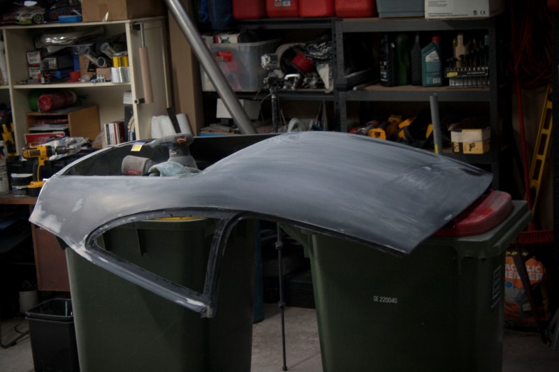
Fastback Part 1
Over the last few weekends I've been doing my least favourite thing, body work. Bleah.
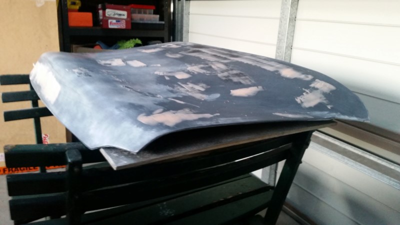
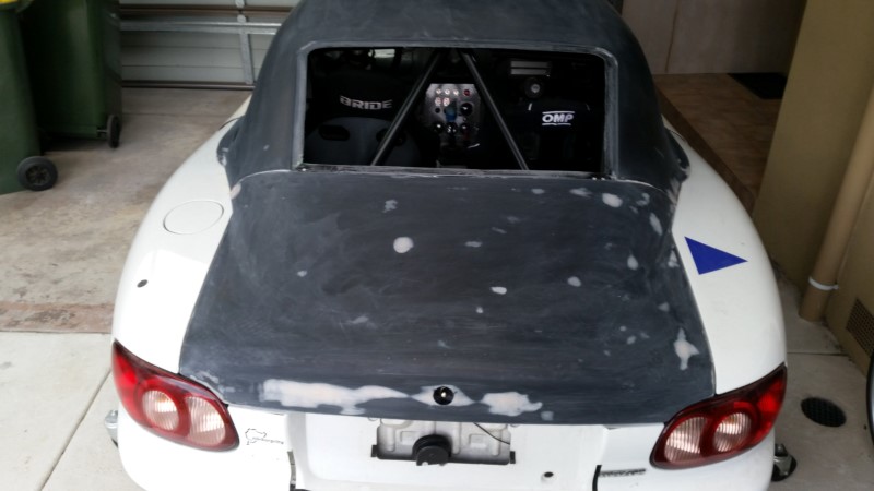
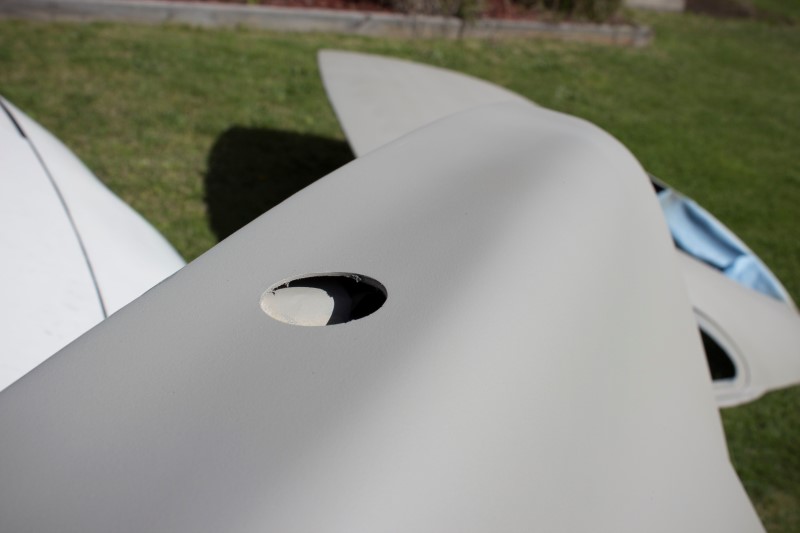
The new roof needs to be sanded, holes filled, painted, windows installed, and finally mounted. I've started on the boot section first, filled all the little pinholes and imperfections.
After many hours fillling and sanding with 120grit, this is where it ended up. You may have noticed the hole right in the middle where the third brake light usually lives.
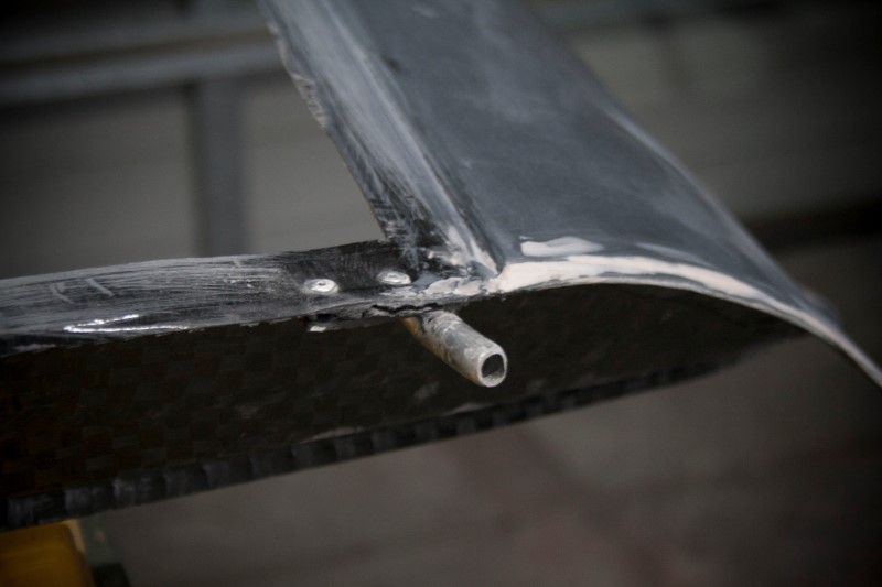
This is the quick latch mount I've gone with.... It has a socket which hooks into a bolt with a spherical end. To remove the boot I just need to push the button and the whole thing pops backwards.
It's a larger size normally for mounting things like bonnets/hoods, but a single latch in the middle here seems to work well.
These apparantly can support upwards of 80kg which should be more than enough considering the boot weighs about 5% of that.
Over the last few weekends I've been doing my least favourite thing, body work. Bleah.
The new roof needs to be sanded, holes filled, painted, windows installed, and finally mounted. I've started on the boot section first, filled all the little pinholes and imperfections.
After many hours fillling and sanding with 120grit, this is where it ended up. You may have noticed the hole right in the middle where the third brake light usually lives.
This is the quick latch mount I've gone with.... It has a socket which hooks into a bolt with a spherical end. To remove the boot I just need to push the button and the whole thing pops backwards.
It's a larger size normally for mounting things like bonnets/hoods, but a single latch in the middle here seems to work well.
These apparantly can support upwards of 80kg which should be more than enough considering the boot weighs about 5% of that.
Reply
0
0
10-20-2016, 07:05 AM
#54
Junior Member
Thread Starter
Join Date: Mar 2011
Location: Melbourne, Australia
Posts: 212
Total Cats: 66
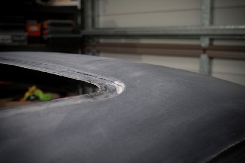
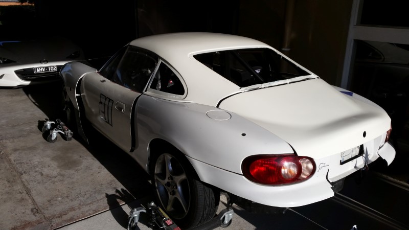
Fastback Part 2
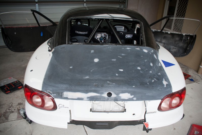
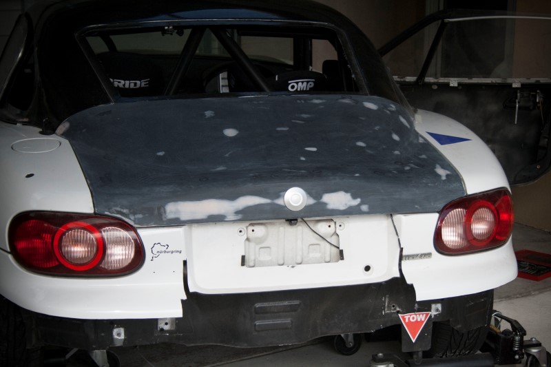
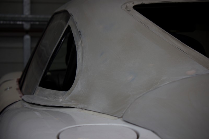
So the roof is all ready for paint now... Main roof section is now sanded
These are the mounting points out the rear of the main roof section, riveted and epoxied on, which the boot slides onto. Its just some aluminium tube welded to a flat alloy strip. The tube slides into holes on the boot.
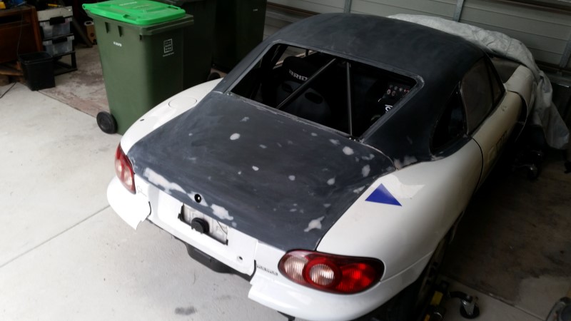
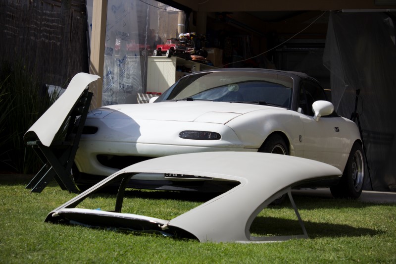
The whole lot back on the car for now. Looking forward to getting it all painted and some windows installed so the car is completely sealed up again.
Well there you go, ready for primer next, and some sanding and perhaps a little more filling before the paint goes on.
So the roof is all ready for paint now... Main roof section is now sanded
These are the mounting points out the rear of the main roof section, riveted and epoxied on, which the boot slides onto. Its just some aluminium tube welded to a flat alloy strip. The tube slides into holes on the boot.
The whole lot back on the car for now. Looking forward to getting it all painted and some windows installed so the car is completely sealed up again.
Well there you go, ready for primer next, and some sanding and perhaps a little more filling before the paint goes on.
Reply
2
2
10-26-2016, 08:02 AM
#55
Junior Member
Thread Starter
Join Date: Mar 2011
Location: Melbourne, Australia
Posts: 212
Total Cats: 66
PAINT!
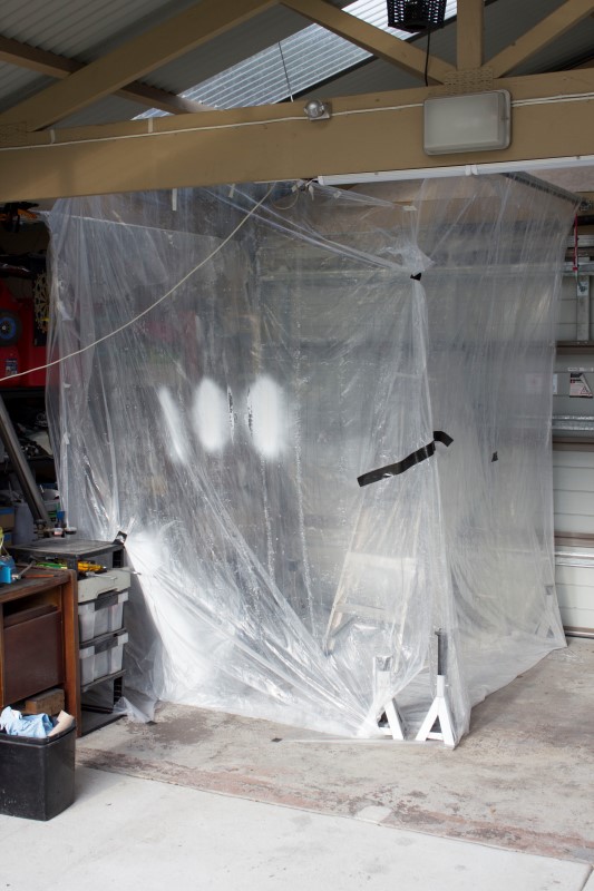
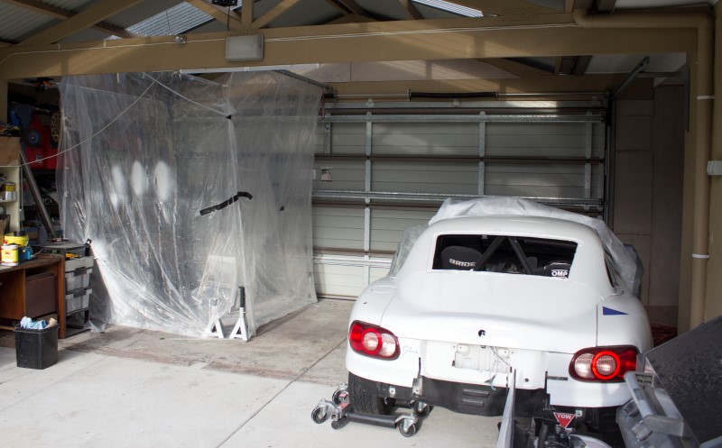
So onto painting, and first off... allow me to introduce you to my makeshift paint booth:
With that I was able to get the parts primered for the first time which was a good feeling.
I then hit the whole lot with some more sanding and filled a few more imperfections.
A final coat of primer to seal it all up. Looking nice and smooth all over now and in the sun to cure well. Special mention to the supercharged NA.
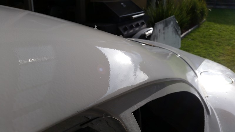
Finally, colour! Looking nice and shiny in what I thought was Mazda 'Pure White'.
I had an apprentice helping out, however the bloke was pretty useless so I fired him.
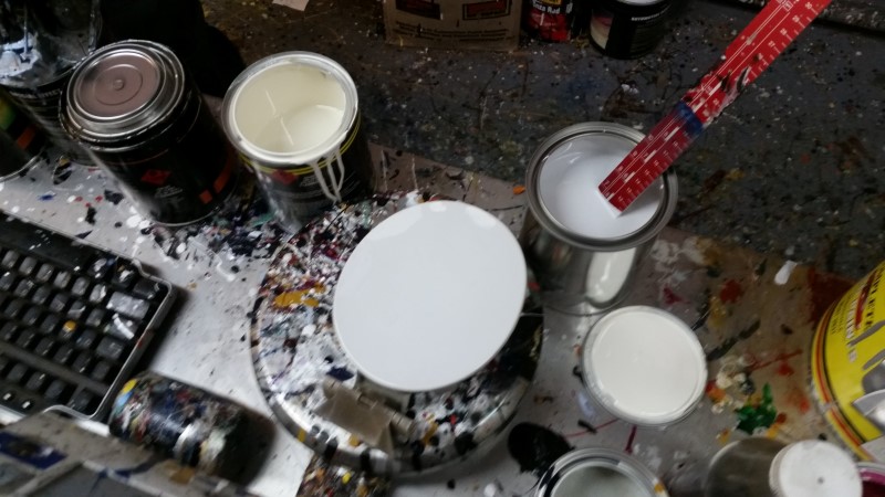
After a day enjoying the sun I set the parts on the car and scratched my head as to why the colour was so off...
It would seem the bloke at the paint shop stuffed up somehow along the way. The colour was too creamy. I went back and he mixed me up another can. He thinks he may have forgotten to add some black to the mix, either that or his paint code software is off. Note the two open cans. On the left is the original colour, on the right is the new mix.
So second attempt at painting and the colour is looking better. The ladder was a good tool for standing the roof up.
A reasonably nice gloss off the gun, and some orange peel. I guess I'm reasonably satisfied with the level of peel. When I get the time I might try sand it out a bit. Anyone know if it's worth the bother? Or will I make it worse?
The end result
Now it needs rear quarter and rear windows, seals and some brackets to mount it to the car, then this milestone is done.
But, gonna start on the exhaust next... and come back to the windows.
So onto painting, and first off... allow me to introduce you to my makeshift paint booth:
With that I was able to get the parts primered for the first time which was a good feeling.
I then hit the whole lot with some more sanding and filled a few more imperfections.
A final coat of primer to seal it all up. Looking nice and smooth all over now and in the sun to cure well. Special mention to the supercharged NA.
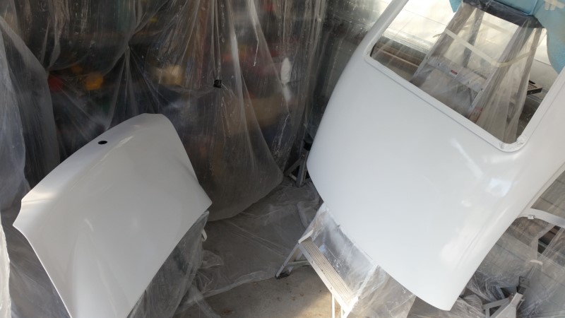
Finally, colour! Looking nice and shiny in what I thought was Mazda 'Pure White'.
I had an apprentice helping out, however the bloke was pretty useless so I fired him.
After a day enjoying the sun I set the parts on the car and scratched my head as to why the colour was so off...
It would seem the bloke at the paint shop stuffed up somehow along the way. The colour was too creamy. I went back and he mixed me up another can. He thinks he may have forgotten to add some black to the mix, either that or his paint code software is off. Note the two open cans. On the left is the original colour, on the right is the new mix.
So second attempt at painting and the colour is looking better. The ladder was a good tool for standing the roof up.
A reasonably nice gloss off the gun, and some orange peel. I guess I'm reasonably satisfied with the level of peel. When I get the time I might try sand it out a bit. Anyone know if it's worth the bother? Or will I make it worse?
The end result
Now it needs rear quarter and rear windows, seals and some brackets to mount it to the car, then this milestone is done.
But, gonna start on the exhaust next... and come back to the windows.
Reply
2
2


 11-02-2016, 06:11 AM
#60
Junior Member
Thread Starter
Join Date: Mar 2011
Location: Melbourne, Australia
Posts: 212
Total Cats: 66
Exhaust!
Well I spent the last few weekends on making up the exhaust...
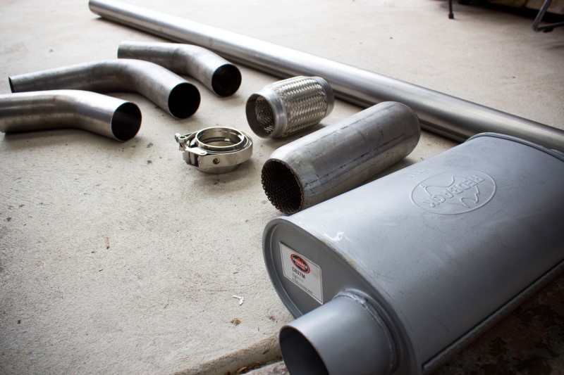
Plan is to run a flex join on the end of the Nitro Dann downpipe which will then mate via a V-band to the rest of the exhaust. The exhaust itself will consist of a hotdog shortly after the V-band, and then a muffler at the rear. I would run less mufflers if I could, but noise restrictions are an issue.
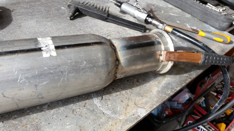
I started by tacking the whole lot together with the MIG. The slip in fitment for the likes of the muffler and the v-bands make welding easier.
However, there is a huge gap around the hotdog ends which made welding those up a bit of a challenge.
Mocking up exhaust tip designs... This upturned style was one concept which got scrapped very quickly. :P
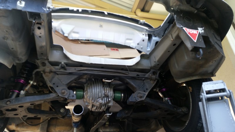
Notice however, I have angled the rear muffler upwards to make sure there is reasonable room for any rear underfloor work/diffuser.
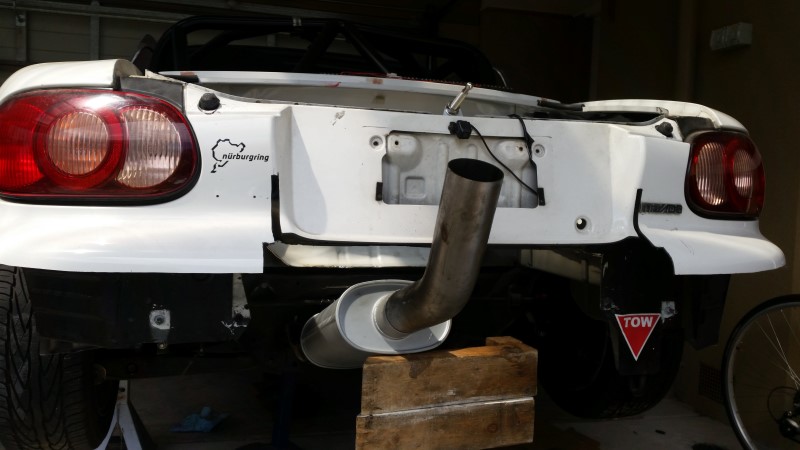
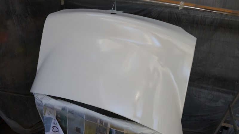
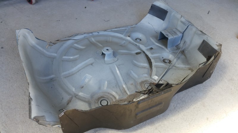
To get the muffler where I wanted it, the boot had to go.
Saved about 3.5kg or roughly 7lbs. Not that heavy In the grand scheme of things, but every gram helps.
Fast forward a week and I spent a morning welding everything up properly. Given this is just old fashioned mild steel, I decided to paint it for a bit of added weathering/longevity. I found this white exhaust paint at the paint shop and figured it would generate some questionable looks...
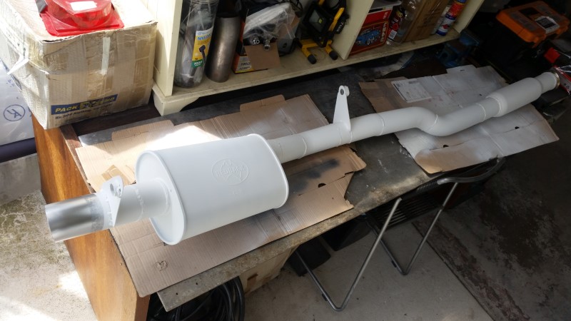
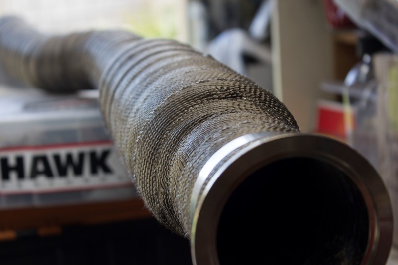
Close up of one of my less sh*tty welds… Actually, lap joint of the v-band was reasonably easy to weld.

Also notice the huge fat hangers I’ve used. They are bolted to the car with round rubber bushes, much stiffer than a traditional hanger, but not completely solid. Hopefully they are sufficient to keep things sturdy yet not cause any metal fatigue type issues. I might need to cut some metal out of them, they do look a bit heavy.
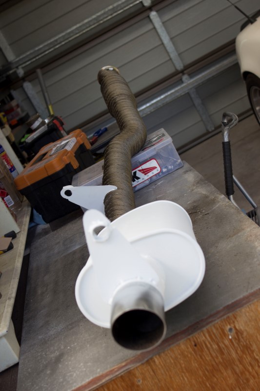
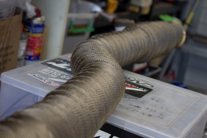
And, last job was to try keep some of the heat out of the cabin/gearbox/flat floor... So I’ve wrapped it all in the DEI titanium stuff. This used up most of a 50 inch length roll (I think it was 50 inch).
I used this stuff on the last exhaust (pre-turbo 2.5” dia zorst) and it seemed to work well.
Next time I’ll hopefully get back to finishing the rest of the roof.
Well I spent the last few weekends on making up the exhaust...
Plan is to run a flex join on the end of the Nitro Dann downpipe which will then mate via a V-band to the rest of the exhaust. The exhaust itself will consist of a hotdog shortly after the V-band, and then a muffler at the rear. I would run less mufflers if I could, but noise restrictions are an issue.
I started by tacking the whole lot together with the MIG. The slip in fitment for the likes of the muffler and the v-bands make welding easier.
However, there is a huge gap around the hotdog ends which made welding those up a bit of a challenge.
Mocking up exhaust tip designs... This upturned style was one concept which got scrapped very quickly. :P
Notice however, I have angled the rear muffler upwards to make sure there is reasonable room for any rear underfloor work/diffuser.
To get the muffler where I wanted it, the boot had to go.
Saved about 3.5kg or roughly 7lbs. Not that heavy In the grand scheme of things, but every gram helps.
Fast forward a week and I spent a morning welding everything up properly. Given this is just old fashioned mild steel, I decided to paint it for a bit of added weathering/longevity. I found this white exhaust paint at the paint shop and figured it would generate some questionable looks...
Close up of one of my less sh*tty welds… Actually, lap joint of the v-band was reasonably easy to weld.
Also notice the huge fat hangers I’ve used. They are bolted to the car with round rubber bushes, much stiffer than a traditional hanger, but not completely solid. Hopefully they are sufficient to keep things sturdy yet not cause any metal fatigue type issues. I might need to cut some metal out of them, they do look a bit heavy.
And, last job was to try keep some of the heat out of the cabin/gearbox/flat floor... So I’ve wrapped it all in the DEI titanium stuff. This used up most of a 50 inch length roll (I think it was 50 inch).
I used this stuff on the last exhaust (pre-turbo 2.5” dia zorst) and it seemed to work well.
Next time I’ll hopefully get back to finishing the rest of the roof.
Reply
0
0


