Build Thread (FE3, RX7 TII, EFR 6258, MS3)
 11-24-2011, 12:25 PM
#221

Man this guy has his farm set up. Theres a wood burning stove behind the pile with a water jacket. That hot water then heats the house, pool and shop. Pretty sweet setup. Plus it doesn't hurt that he gets all the wood for free from the Amish lumber mill down the road. Winning.

Reply
 0
0

0
11-25-2011, 04:00 PM
#224
Isolators (aka scrap rubber hose) for radiator mounted per M2s suggestion. Worked on some more wiring odds and ends, mounted relays and soldered on pigtails and such. I discovered that my oil pan has a small leak somewhere.. freakin sucks. I'm not going to worry about it for now since the engine is all bolted in and id probably need to pull the engine again to fix it. the friend that's helping me out with my wiring is supposed to be coming over on Sunday afternoon so hopefully we'll get more of it knocked out then. 2 ish weeks till schools out for winter break. 
Reply
0
0
12-11-2011, 08:56 PM
#225
So instead of studying for finals i thought id work on the car this weekend.
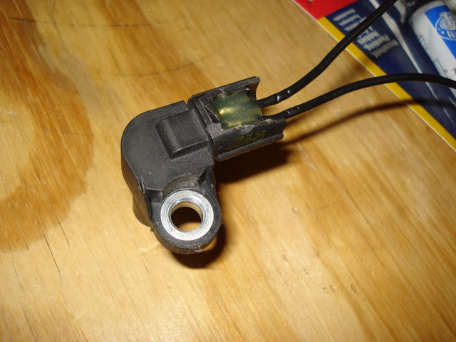
Didnt have a pigtail for the hall sensor im using for crank position. soldered 2 wires to the pins, filled it up with hot glue and sealed it up with JB weld.
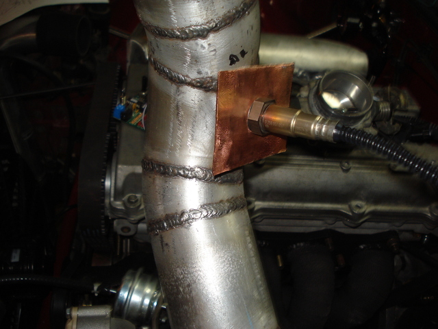
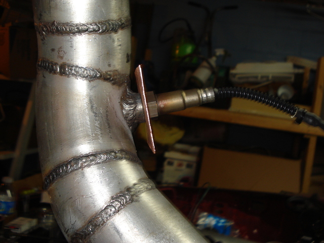
O2 bung welded in. i saw somewhere someone using a copper heat sink for their O2 so i went ahead and did it since i had some copper pipe laying around.
Drilled and taped the intake manifold for vacuum lines.
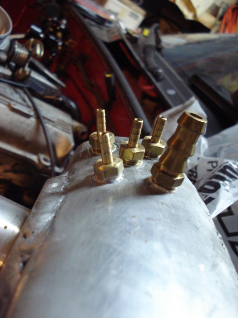
Made the hydraulic line for the clutch as well.
After this next week i should be making some faster progress in this build. School will be out and ill only have work to deal with.
Didnt have a pigtail for the hall sensor im using for crank position. soldered 2 wires to the pins, filled it up with hot glue and sealed it up with JB weld.
O2 bung welded in. i saw somewhere someone using a copper heat sink for their O2 so i went ahead and did it since i had some copper pipe laying around.
Drilled and taped the intake manifold for vacuum lines.
Made the hydraulic line for the clutch as well.
After this next week i should be making some faster progress in this build. School will be out and ill only have work to deal with.
Last edited by yank; 12-12-2011 at 12:00 AM.
Reply
0
0
12-22-2011, 12:06 AM
#226
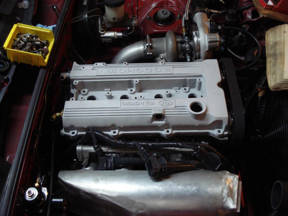
Been working on alot of wiring so far this week. stopped by a local monument place and got the valve cover sand blasted. Im thinking gloss or chrome black as of right now. My plans for the car color wise is all black + hardtop and white cage.
Wiring wise im making 4 main runs. each headlight comes together and ties together then all the sensors that are attached to the main sensor ground are all run together and lastly the high current stuff like the fan and water pump will be run in one loom.
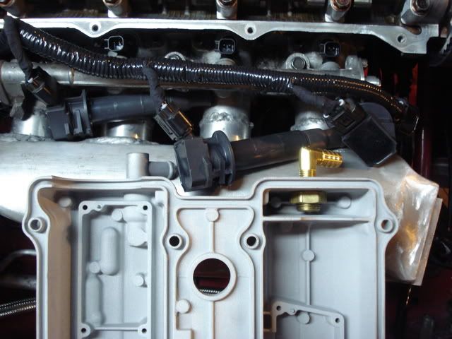
Added a second vent to the valve cover tonight as well.
Wiring wise im making 4 main runs. each headlight comes together and ties together then all the sensors that are attached to the main sensor ground are all run together and lastly the high current stuff like the fan and water pump will be run in one loom.
Added a second vent to the valve cover tonight as well.
Reply
1
1
12-27-2011, 07:51 PM
#227
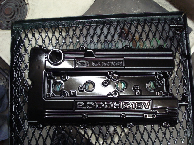
Had a few hours to kill the other day so I went to a friend’s house and we powder coated the valve cover. Didn’t spend a lot of time on the prep work so considering it came out pretty amazing. Gloss black and clear.
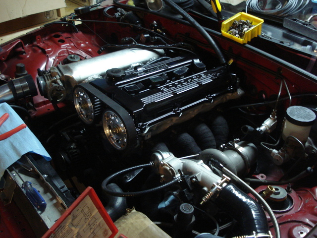
I’ve been making some good progress over the last couple days with the wiring although visually it’s hard to tell. I have to get the cam position sensor and the engine temp gauge that goes to the cluster into the car and then all the runs will be made to the fuse box area.
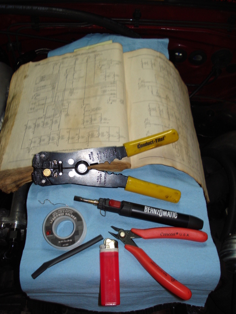
Here is a few things that are making this process more bearable.
Butane torch for soldering. This thing is freaking awesome! I’m able to solder small stuff and even big stuff up to 8 gauge. Quick wire stripper. Im kinda torn on this one because it needs to be used with caution. If you just throw the wire down in there and crimp it’s almost certain that 4 or 5 strands of wire will get cut and tossed. On the other hand if you press halfway and rotate the wire and finish the strip you can usually keep the wire intact. If I would have thrown down some money and gotten a better quality one I might not be having this issue.. 99% of the wire joints have been soldered and shrink wrapped as per my electrical helpers commands. (Had ~one that got tape instead of heat shrink..)
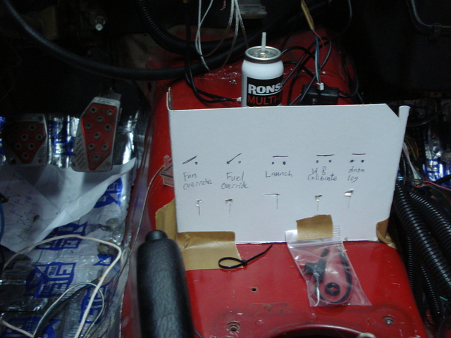
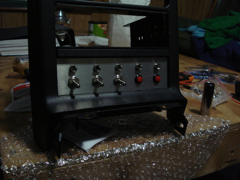
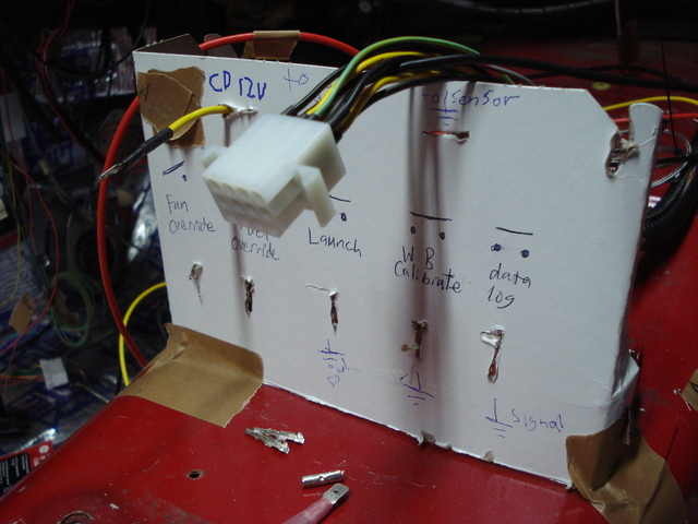
The current layout for the switches in the dash is as follows. Off shot is an on / off table switch. If you guys see anything else I should have in here let me know.. (Fuel override should be fuel pump kill switch)
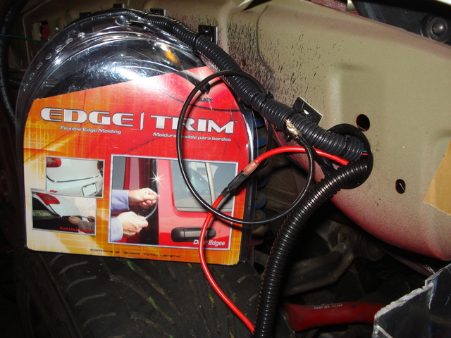
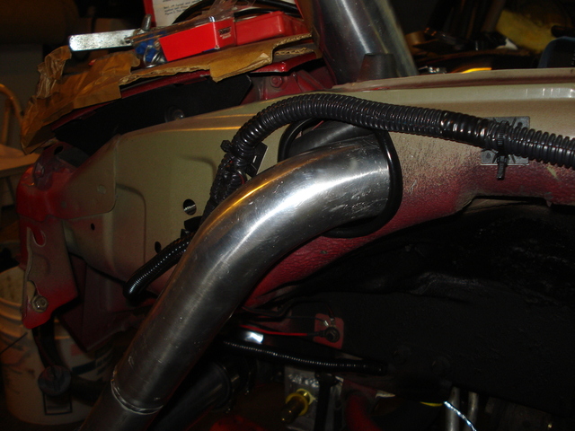
I had the idea to run some of this door trim stuff to make grommets in different places. It’s a pain to work with but it ended up working out really nice.
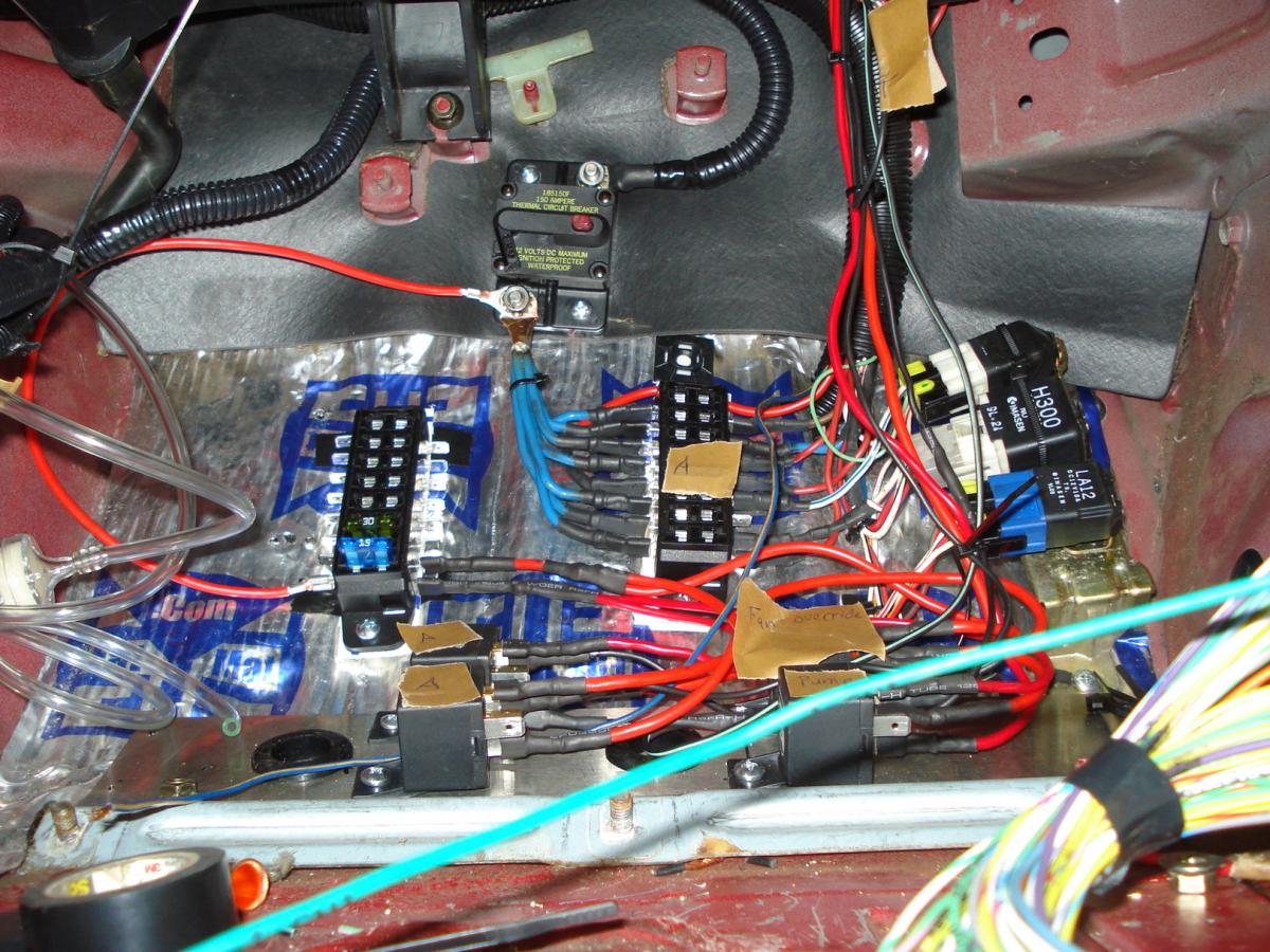
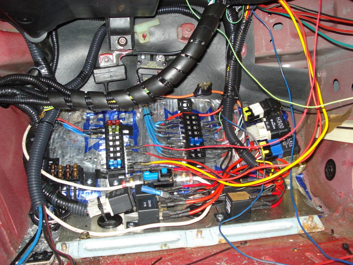
This is what the fuse panel looks like as of tonight.
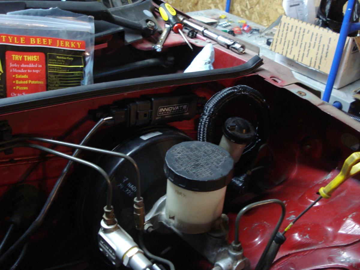
Question #1. Do you think this is a bad place to mount the LC-1 module? I can’t get the huge clip through my current grommet and I’d rather not make another hole in the chassis. Keeping the module in the engine bay will make it easy for me to remove the O2 if for some reason I need to take it out. Plus I don’t think it looks horrible if its mount it nice.
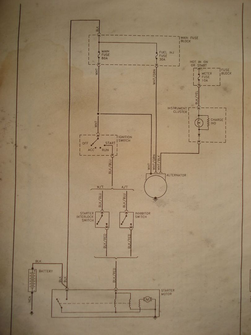
Question #2 the wire coming out of the ignition for the start ( cranking) position is a 12 gauge wire that according to the manual goes to a starter interlock switch. Is this the clutch pedal pressure sensor? the wires coming out of the clutch switch are like 22 gauge along with the wire going to the starter solenoid. The wire gauge difference has me stumped. What am i missing here?
I’ve been making some good progress over the last couple days with the wiring although visually it’s hard to tell. I have to get the cam position sensor and the engine temp gauge that goes to the cluster into the car and then all the runs will be made to the fuse box area.
Here is a few things that are making this process more bearable.
Butane torch for soldering. This thing is freaking awesome! I’m able to solder small stuff and even big stuff up to 8 gauge. Quick wire stripper. Im kinda torn on this one because it needs to be used with caution. If you just throw the wire down in there and crimp it’s almost certain that 4 or 5 strands of wire will get cut and tossed. On the other hand if you press halfway and rotate the wire and finish the strip you can usually keep the wire intact. If I would have thrown down some money and gotten a better quality one I might not be having this issue.. 99% of the wire joints have been soldered and shrink wrapped as per my electrical helpers commands. (Had ~one that got tape instead of heat shrink..)
The current layout for the switches in the dash is as follows. Off shot is an on / off table switch. If you guys see anything else I should have in here let me know.. (Fuel override should be fuel pump kill switch)
I had the idea to run some of this door trim stuff to make grommets in different places. It’s a pain to work with but it ended up working out really nice.
This is what the fuse panel looks like as of tonight.
Question #1. Do you think this is a bad place to mount the LC-1 module? I can’t get the huge clip through my current grommet and I’d rather not make another hole in the chassis. Keeping the module in the engine bay will make it easy for me to remove the O2 if for some reason I need to take it out. Plus I don’t think it looks horrible if its mount it nice.
Question #2 the wire coming out of the ignition for the start ( cranking) position is a 12 gauge wire that according to the manual goes to a starter interlock switch. Is this the clutch pedal pressure sensor? the wires coming out of the clutch switch are like 22 gauge along with the wire going to the starter solenoid. The wire gauge difference has me stumped. What am i missing here?
Reply
0
0
12-28-2011, 02:35 PM
#229
mkturbo.com


iTrader: (24)
Join Date: May 2006
Location: Charleston SC
Posts: 15,177
Total Cats: 1,681
Question #1. Do you think this is a bad place to mount the LC-1 module? I can�t get the huge clip through my current grommet and I�d rather not make another hole in the chassis. Keeping the module in the engine bay will make it easy for me to remove the O2 if for some reason I need to take it out. Plus I don�t think it looks horrible if its mount it nice.
Reply
0
0
01-03-2012, 07:18 PM
#230
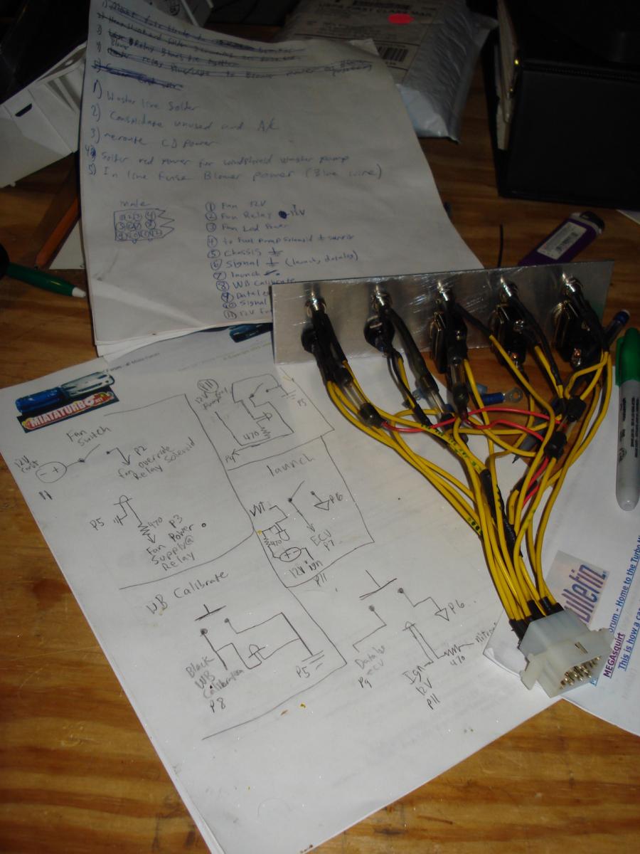
Thanks Shuiend. I'll go ahead and mount it there then. Alots been going down with the car but i havent had a chance to take pics yet. just finished this DIY Switch panel with LEDs and im about to go wire it up. Pretty happy with it. May do a brushed finish or powdercoat later.. idk.
Reply
0
0
01-05-2012, 07:58 PM
#231
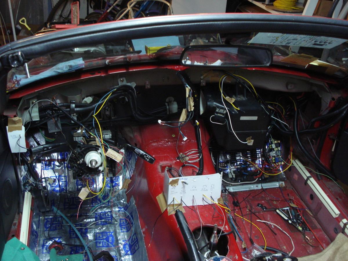
If you ever thought wiring your Miata from scratch was a good idea think again. This is where i'm at with the fuse box area for now. Getting everything sorted out takes alot of time. Waaay more than i thought it would. Im learning alot in the mean time though. The most useful thing im walking away with is knowing how to hook up relays and incorporating if / or logic to the circuits using relays. Once we get the gauge cluster harness hooked up and the ignition, acc. power wires hooked up to the corresponding terminals i should be good to start her up!
Couldn't find a plug to fit the FE3 cam angle sensor so i found a plug that had similar shaped sockets that would fit the pins of the CAS. destroyed the plug and harvested the sockets. Ill come up with something to hold them at equal spacing and keep them in order. (not sure what the order needs to be yet...)
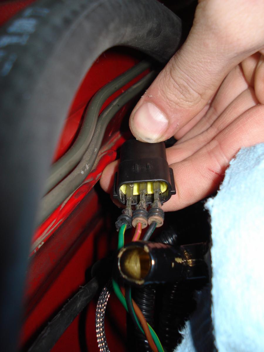
Couldn't find a plug to fit the FE3 cam angle sensor so i found a plug that had similar shaped sockets that would fit the pins of the CAS. destroyed the plug and harvested the sockets. Ill come up with something to hold them at equal spacing and keep them in order. (not sure what the order needs to be yet...)
Reply
0
0
 01-07-2012, 09:28 AM
#233
Thanks. Its been way more work than i thought it would be. Not gonna lie, i miss driving my car pretty bad right now.
Reply
0
0
 I'm glad that's not on my project list.
01-10-2012, 10:44 PM
I'm glad that's not on my project list.
01-10-2012, 10:44 PM
#235
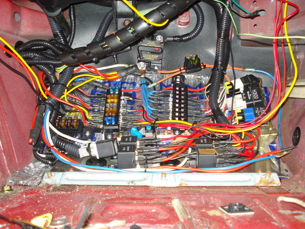
Alright! done in here... Hopefully. Im going to add some fuses and put some of this in loom yet and then i should be on to bigger and better things. If you see anything that needs to be addressed or you're curious as to how i have things wired up let me know!
Next ill be working on this harness that goes to all the switches and LEDs in the switch panel.
After i get this done i'll only have the 2 harnesses that connect to the back of the gauge cluster and the wiring should be sorted out. It'd be awesome if i could turn the key this weekend!
Next ill be working on this harness that goes to all the switches and LEDs in the switch panel.
After i get this done i'll only have the 2 harnesses that connect to the back of the gauge cluster and the wiring should be sorted out. It'd be awesome if i could turn the key this weekend!
Reply
0
0
 01-14-2012, 12:36 PM
#237
Finished the switch side of the harness. Still need to add provisions for the launch control LED on the male side. Added .5A fuses to the LEDs and anything going to the ECU.
I've been getting the impression that i should get started on the tuning side of this build so i've been RingTFM. Its slow going finding the information i need but I'll get there eventually.
FYI School starts back in a week which means i wont get to touch this project much..
I've been getting the impression that i should get started on the tuning side of this build so i've been RingTFM. Its slow going finding the information i need but I'll get there eventually.
FYI School starts back in a week which means i wont get to touch this project much..
Reply
0
0
04-22-2012, 04:58 PM
#238
School gets out in about 3 weeks so i'll be back on this project every day after work. I decided to make my life easier and control some of the LEDs from a double pole switch instead of with the ECU. it took a little more wiring of my switch panel but its working now. Also added a dimmer circuit to the LEDs. switches from straight ground to ~1000 Ohm power resistor via relay and headlight hot. also not seen here is a table switch and LED which is also wired into the dimmer circuit. Here's a quick walk around with my high quality video camera. 
Reply
0
0


