Chiburbian's 01' Lots of potential, no follow-through build
 11-02-2011, 11:07 AM
#21
Elite Member

Thread Starter
iTrader: (1)
Join Date: Feb 2008
Location: Loganville, GA
Posts: 2,331
Total Cats: 202
y8s, thanks but robots scare me.
How about using an uninsulated butt splice, crimp wire side, fill other side with solder, set on pin, heat till solder melts, drop it on over?
Only problem is darn butt splices cost about $.44 each. Thats a lot of money but money well spent if it works.
I will try and source a single butt splice. If that doesn't work I will look into the robot.
Let me know if my idea is flawed though.

Reply
 0
0

0
11-02-2011, 11:36 AM
#23
Elite Member
Thread Starter
iTrader: (1)
Join Date: Feb 2008
Location: Loganville, GA
Posts: 2,331
Total Cats: 202
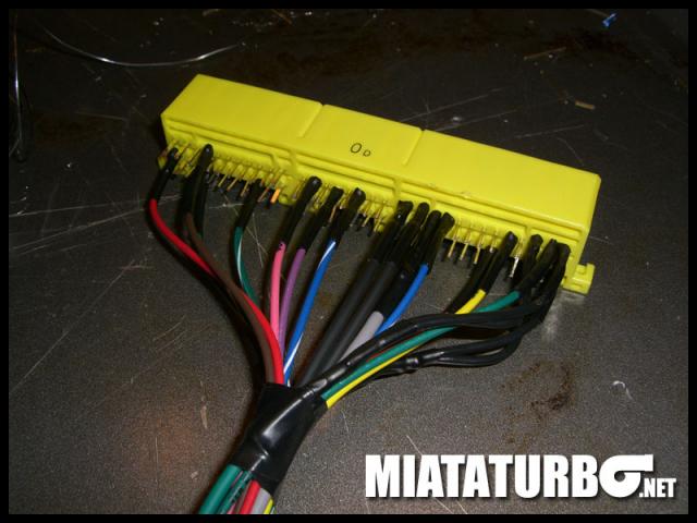
ECU side pins on 72 pin (ECU style connector) to 18AWG wire. I might have made a mistake by going 18 gauge but its too late now.
I will try and take a picture tonight when I get off of work.
Here is a link to the connector:
http://www.te.com/catalog/pn/en/1123...RQPN=1123038-2
I actually ordered a couple sets of the ones that have all 72 pins if anyone needs one.
Oh, and I had to order a couple things from DIYautotune so I ordered the mapdaddy while I was at it. It is installed and seems to be working fine.
Last edited by Chiburbian; 11-02-2011 at 11:52 AM.
Reply
0
0
11-03-2011, 10:20 PM
#24
Elite Member
Thread Starter
iTrader: (1)
Join Date: Feb 2008
Location: Loganville, GA
Posts: 2,331
Total Cats: 202
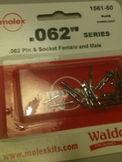
I abandoned the idea of soldering the wires side by side. I found something I think works. Ideally I would only have the female side of the below pins, but they came male and female so I took the male side and punched the center out with a tiny screwdriver so it would fit over the pin on the harness side. I then filled the connector with solder to join it to the pin. Seems to work great. Lots of work though. Here are the pins I used:
Here is where I am at with the harness as we speak:
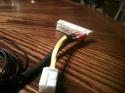
Wires with white heat shrink go to ECU. Wires that go to Megasquirt OR are shared between megasquirt and ECU have red heat shrink.
<<Oh, and Dropbox for the win. If anyone doesn't have an account and would like to get 250mb on top of your standard 2gb free... CLICK HERE for 250mb>>
Here is where I am at with the harness as we speak:
Wires with white heat shrink go to ECU. Wires that go to Megasquirt OR are shared between megasquirt and ECU have red heat shrink.
<<Oh, and Dropbox for the win. If anyone doesn't have an account and would like to get 250mb on top of your standard 2gb free... CLICK HERE for 250mb>>
Reply
0
0
11-08-2011, 12:28 AM
#25
Elite Member
Thread Starter
iTrader: (1)
Join Date: Feb 2008
Location: Loganville, GA
Posts: 2,331
Total Cats: 202
Decision time... I don't mind the "clutch in to shift" thing too much but if I can eliminate that at the same time as having a "launch control" disable switch, I think I may want to do that.
Initially I was hoping to just have a switch that simply provides a ground to my clutch circuit, but this would also have the effect of making my car think the clutch is IN constantly, correct?
I am trying to figure out a way for this to work that doesn't involve relays. Ideas?
Initially I was hoping to just have a switch that simply provides a ground to my clutch circuit, but this would also have the effect of making my car think the clutch is IN constantly, correct?
I am trying to figure out a way for this to work that doesn't involve relays. Ideas?
Reply
0
0
11-08-2011, 12:38 AM
#26
Elite Member
Thread Starter
iTrader: (1)
Join Date: Feb 2008
Location: Loganville, GA
Posts: 2,331
Total Cats: 202
Double update. I finished the jumper harness tonight. I decided that I never want to do it again. I must have 8-10 hours into it and its not half as good as I had hoped.
Pictures will be posted as soon as my damn phone syncs. Maybe morning by the way its looking.
Now I just have to figure out how to route the wires I will need to route in such a way that I don't feel too ghetto.
I need to bring the wideband wire into the cab and I will probably pre-run wires for boost control and four coils. Anything else electronic wise I should run to future proof it? Oh *****, I will have to run oil pressure at some point anyhow, so never mind.
F*ck!
Anyhow. Wideband. And see if my ghetto harness gives me cam and crank signal.
I hope to give the car its first MS crank tomorrow after work. I will report more later.
Reply
0
0
 11-08-2011, 11:39 AM
#28
Elite Member
Thread Starter
iTrader: (1)
Join Date: Feb 2008
Location: Loganville, GA
Posts: 2,331
Total Cats: 202
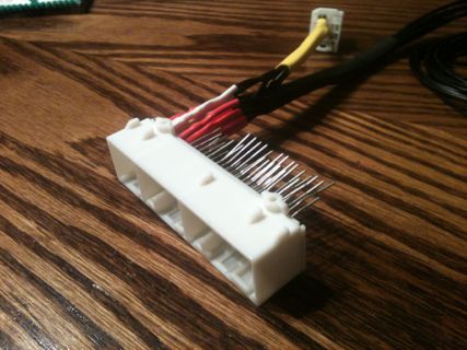
I did cut the pins short. They were maybe 3/8" long when I soldered them.
I just left them long for the picture.
The reason why the heat shrink is so long is because of the method I used to attatch the wires and I wanted the heat shrink long for strain relief.
My frustration wasn't so much the individual steps, just that there were so many of them and I had to double and triple check myself to make sure nothing was switched etc.
Reply
0
0
11-12-2011, 02:41 PM
#29
Elite Member
Thread Starter
iTrader: (1)
Join Date: Feb 2008
Location: Loganville, GA
Posts: 2,331
Total Cats: 202
Update: having problems getting power to Megasquirt. Pin 4AF has less than a volt going to it even when testing at car harness. Does the car somehow keep that pin low until engine is spinning? I swear the first time I tested it I had 12v at ms pin 28... Any ideas?
Reply
0
0
11-13-2011, 03:26 PM
#30
Elite Member
Thread Starter
iTrader: (1)
Join Date: Feb 2008
Location: Loganville, GA
Posts: 2,331
Total Cats: 202
Problem solved. It seems that the 30A fuse labeled Fuel under the hood also has some part to play in allowing power to the ecu.
I was pulling it in order to avoid having to find the fuel injector harness. Will report back later.
I was pulling it in order to avoid having to find the fuel injector harness. Will report back later.
Reply
0
0
11-13-2011, 09:12 PM
#32
Elite Member
Thread Starter
iTrader: (1)
Join Date: Feb 2008
Location: Loganville, GA
Posts: 2,331
Total Cats: 202
Having issues with vr adjustment again. According to Franks Westfield (specifically ms3x board) build you start with r11 fully ccw, then turn clockwise while measuring voltage across r17. (technically he says from r17 to pin 3 of u7 but I cannot see how that is different from what I am doing.)
I cannot get any voltage to indicate past .026v no matter how far cw I turn the pot. According to his instructions I should try and get between 2.5-3v.
EDIT: Going off of Joe Perez' instructions in a previous thread I metered from R11 to ground and R54 to ground bringing both to approximately 2.5 volts. Still no RPMs
Either I am doing the metering wrong (likely) or my cam or crank wiring is not setup correctly. I have about 1.5 feet of wiring (max) between MS and stock harness. Should I have used shielded wire for such a short run on those two? I didn't see any shielded wire on the stock wiring...
Last edited by Chiburbian; 11-14-2011 at 09:59 AM.
Reply
0
0
 11-14-2011, 11:53 AM
#34
Boost Czar

iTrader: (62)
Join Date: May 2005
Location: Chantilly, VA
Posts: 79,484
Total Cats: 4,076
Having issues with vr adjustment again. According to Franks Westfield (specifically ms3x board) build you start with r11 fully ccw, then turn clockwise while measuring voltage across r17. (technically he says from r17 to pin 3 of u7 but I cannot see how that is different from what I am doing.)
I cannot get any voltage to indicate past .026v no matter how far cw I turn the pot. According to his instructions I should try and get between 2.5-3v.
EDIT: Going off of Joe Perez' instructions in a previous thread I metered from R11 to ground and R54 to ground bringing both to approximately 2.5 volts. Still no RPMs
Either I am doing the metering wrong (likely) or my cam or crank wiring is not setup correctly. I have about 1.5 feet of wiring (max) between MS and stock harness. Should I have used shielded wire for such a short run on those two? I didn't see any shielded wire on the stock wiring...
I cannot get any voltage to indicate past .026v no matter how far cw I turn the pot. According to his instructions I should try and get between 2.5-3v.
EDIT: Going off of Joe Perez' instructions in a previous thread I metered from R11 to ground and R54 to ground bringing both to approximately 2.5 volts. Still no RPMs
Either I am doing the metering wrong (likely) or my cam or crank wiring is not setup correctly. I have about 1.5 feet of wiring (max) between MS and stock harness. Should I have used shielded wire for such a short run on those two? I didn't see any shielded wire on the stock wiring...
This worked for me:
For hall or optical sensor inputs, solder (or install) a jumper across JP7
The cam input adjustment potentiometers should be set as follows. Turn both pots (R11 and R32) full anti-clockwise - approx 6 turns (you may feel a "click" when the end position is reached, they can't be damaged by turning too far.) Then turn the top one (R11) two turns clockwise.
The cam input adjustment potentiometers should be set as follows. Turn both pots (R11 and R32) full anti-clockwise - approx 6 turns (you may feel a "click" when the end position is reached, they can't be damaged by turning too far.) Then turn the top one (R11) two turns clockwise.
Reply
0
0
11-15-2011, 01:10 PM
#37
Elite Member
Thread Starter
iTrader: (1)
Join Date: Feb 2008
Location: Loganville, GA
Posts: 2,331
Total Cats: 202
Well, I checked the wiring and found that I had wired the cam signal to the ms instead of the expansion.
Plugged in crank only and left daughter card off. Started with r56 in fully ccw position and cranked car while turning r56 about one turn at a time while monitoring tooth logger.
Once I got reliable signal on the tooth logger I disconnected ms and installed 3x card. I started with r11 fully ccw and rotated by one turn per attempt.
I am not seeing a green line nor am I seeing any rpms indicated, but I am getting to the point where the red sync error bar is starting to show up.
I realize this is not the way it seems it should be done, but it's the only way I have been getting any results.
I am however having probs with tuner studio on the Mac side. I will try again tonight with tuner studio in windows. Will post composite log when I get home. Got tired fighting with it last night to the point where I was liable to make dumb mistakes.
Last edited by Chiburbian; 11-15-2011 at 02:56 PM.
Reply
0
0
11-15-2011, 10:37 PM
#40
Elite Member
Thread Starter
iTrader: (1)
Join Date: Feb 2008
Location: Loganville, GA
Posts: 2,331
Total Cats: 202
Which is weird considering that the only way I can get that to even appear is to crank on the vr pots...
Any ms gurus in the Chicagoland area? At this point I am willing to pay or trade.
Any ms gurus in the Chicagoland area? At this point I am willing to pay or trade.
Reply
0
0


