f20c engine conversion

 07-19-2010, 01:24 PM
#162

Those numbers sure make for a compelling swap ... especially with how cheap I've seen these drivetrains going for locally. Alas ... my fabrication skills do not include welding nor do I have a girlfriend with the attention span to a lot myself that much time in the shop.
Thanks for the detailed updates and congratulations on job well done.
-Zach

Reply
 0
0

0
07-19-2010, 04:27 PM
#163
Senior Member
Thread Starter
iTrader: (2)

Join Date: Jan 2010
Location: Denver
Posts: 904
Total Cats: 14
^^^ You nailed it I weigh 170. The engine weighs a bit less than a Miata power plant the transmission a bit more, it is basically a push. However, a little weight is transferred to the rear of the car due to the transmission being heavier and a bit longer.
Im sure weight distribution will change back to the front by a few tenths of a percent due to the added weight of the turbo, manifold, and IC.
Thanks for the kudos!
I just came in the house from the garage, I was looking at supply and return lines and may have an issue with oil return. Here are a couple of pictures.
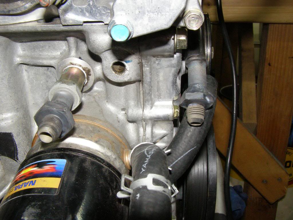
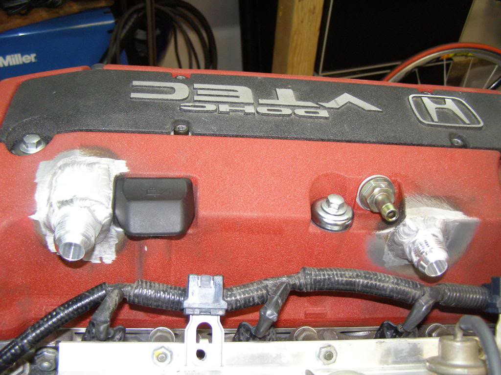
In this picture you can see my water feed and return fittings attached to the engine. I will be relocating the oil filter and doing away with the water to oil cooler/warmer. If you look closely you will also notice the journal where the oil pressure sending unit lives. This will be utilized for oil supply to the turbo and to the mechanical oil pressure gauge.
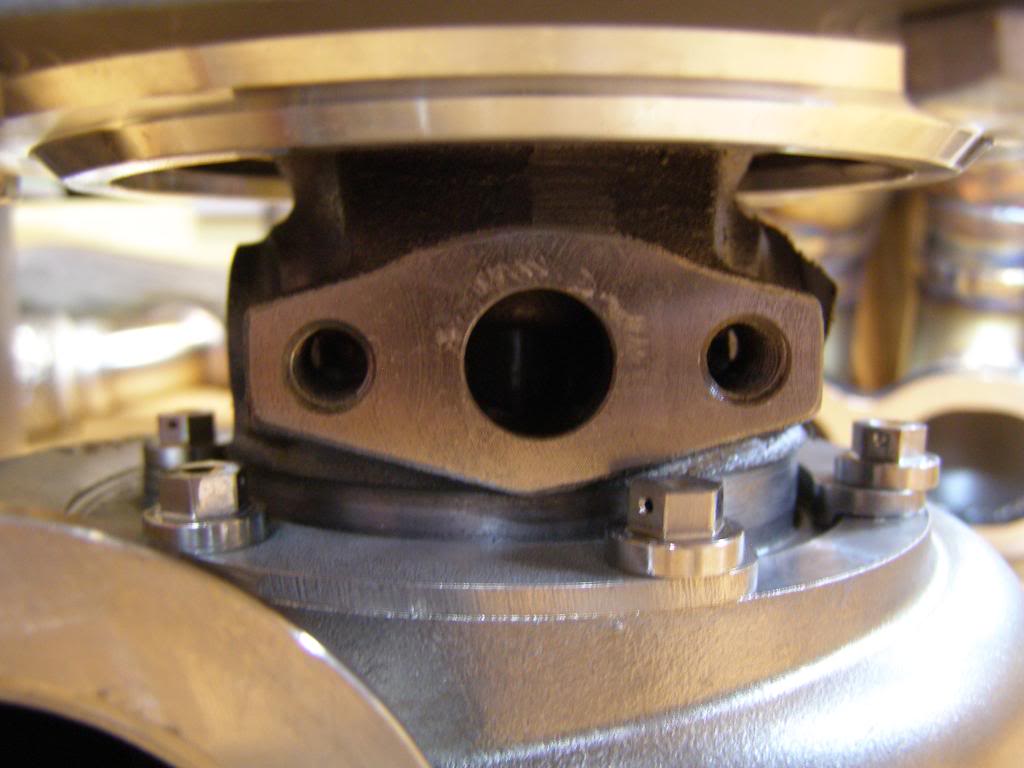
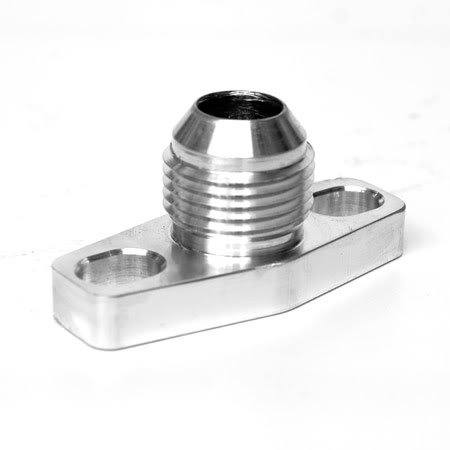
Here is where the oil return is going to bolt up. I received a gasket with the turbo but no fitting for the return; kind of strange. I am going to look online and see what I can find. Worse case I will take some plate aluminum and weld a bung to it.
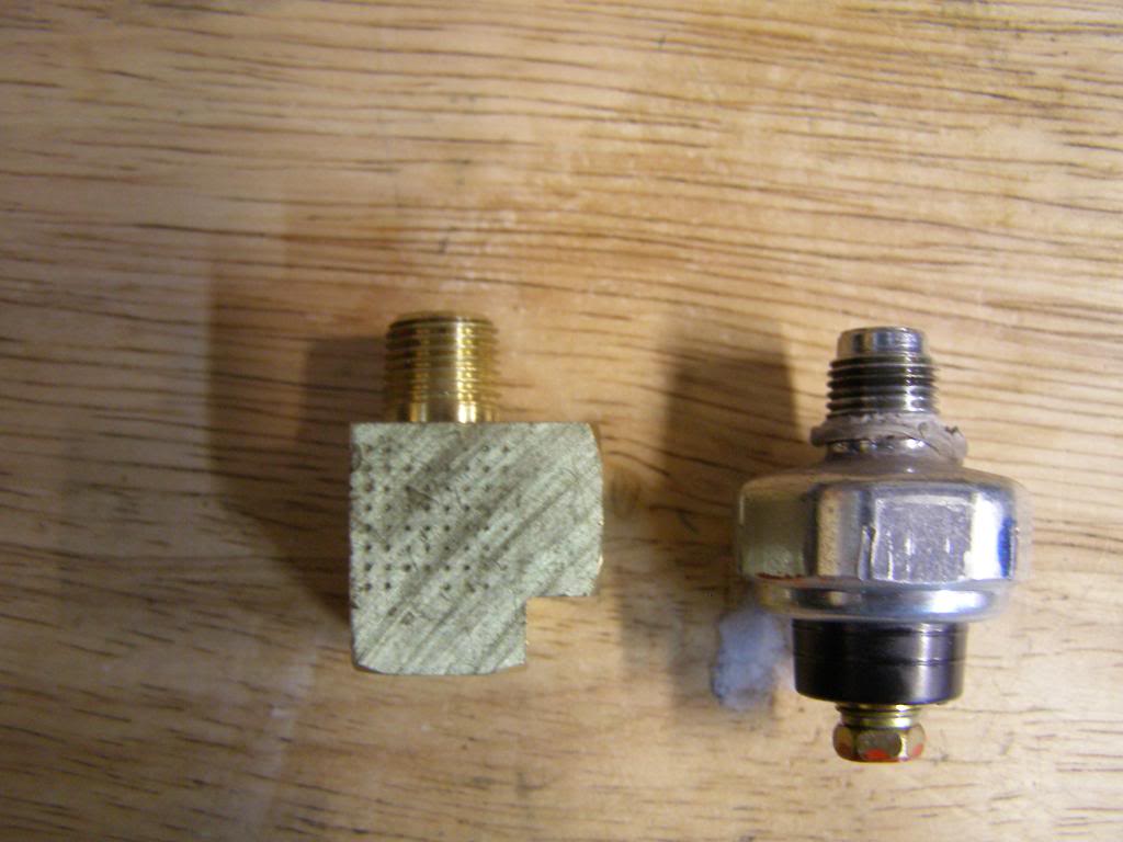
Here is the bigger issue. Oil pressure sensor, and the fitting I was supplied with for oil supply. The sending unit is standard thread, while the new fitting is NPT...this is not going to work! The oil sending unit is also flared at the tip to seat into the block and create a leak free fit. I guess it is off to the speed shop... hope I get lucky
Im sure weight distribution will change back to the front by a few tenths of a percent due to the added weight of the turbo, manifold, and IC.
Thanks for the kudos!
I just came in the house from the garage, I was looking at supply and return lines and may have an issue with oil return. Here are a couple of pictures.
In this picture you can see my water feed and return fittings attached to the engine. I will be relocating the oil filter and doing away with the water to oil cooler/warmer. If you look closely you will also notice the journal where the oil pressure sending unit lives. This will be utilized for oil supply to the turbo and to the mechanical oil pressure gauge.
Here is where the oil return is going to bolt up. I received a gasket with the turbo but no fitting for the return; kind of strange. I am going to look online and see what I can find. Worse case I will take some plate aluminum and weld a bung to it.
Here is the bigger issue. Oil pressure sensor, and the fitting I was supplied with for oil supply. The sending unit is standard thread, while the new fitting is NPT...this is not going to work! The oil sending unit is also flared at the tip to seat into the block and create a leak free fit. I guess it is off to the speed shop... hope I get lucky
Reply
0
0


 07-19-2010, 09:20 PM
#168
Senior Member
Thread Starter
iTrader: (2)
Join Date: Jan 2010
Location: Denver
Posts: 904
Total Cats: 14
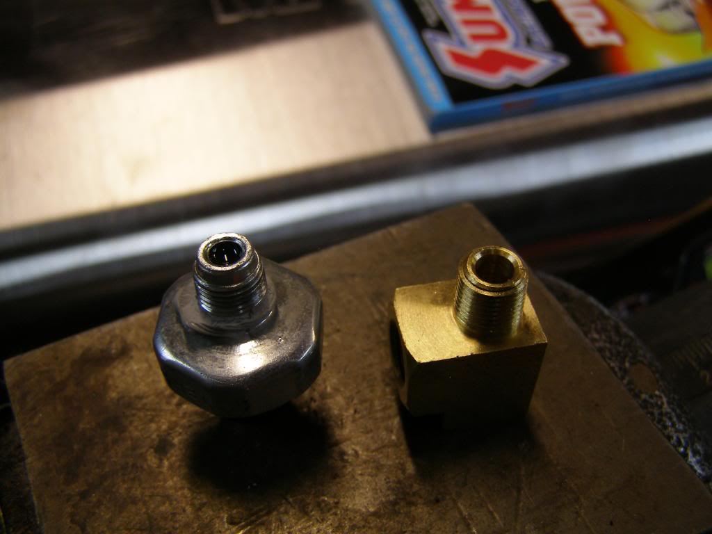
After spending some time at the speed shop I found out that the thread on the oil pressure sending unit is actually bpt (british pipe thread) 27 threads per inch. The original T fitting is npt 28 tpi. The shop that I went to had an adapter. So this is what I have, adapter into engine t fitting into adapter. The two adapter outputs will supply the turbo and the mechanical oil pressure gauge.
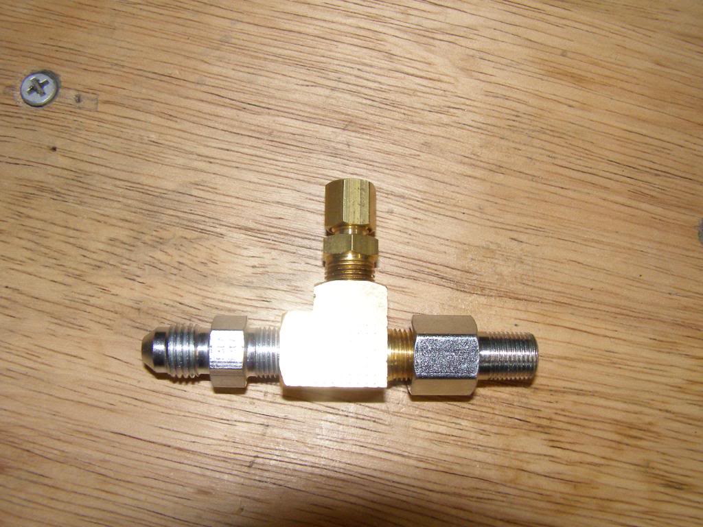
I may place one more t fitting so I can run the stock oil pressure sending unit as well. Doing this will allow me to set up and data log oil pressure, although I am not sure I need to do that.
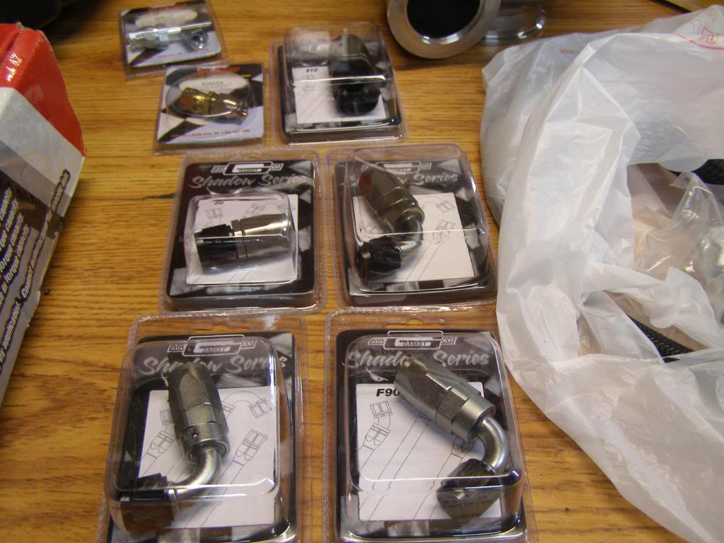
I also picked up the fittings needed to plumb the turbo.
Stay tuned more updates to come!!!
I may place one more t fitting so I can run the stock oil pressure sending unit as well. Doing this will allow me to set up and data log oil pressure, although I am not sure I need to do that.
I also picked up the fittings needed to plumb the turbo.
Stay tuned more updates to come!!!
Last edited by hingstonwm; 07-20-2010 at 03:08 AM.
Reply
0
0
07-19-2010, 10:17 PM
#173
Elite Member

iTrader: (9)
Join Date: Jun 2006
Location: Chesterfield, NJ
Posts: 6,893
Total Cats: 399

When I order turbines separately the metal pieces and bolts are in their own bag jammed inside the scroll. Tial will sell their dealers whatever you need separately if you can't track it down.
Anyway, this is my way of subscribing to this incredible build

Reply
0
0
07-27-2010, 05:41 AM
#175
Senior Member
Thread Starter
iTrader: (2)
Join Date: Jan 2010
Location: Denver
Posts: 904
Total Cats: 14
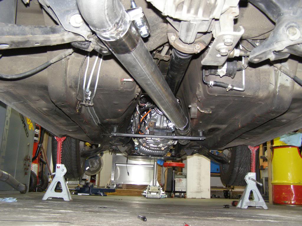
Another small update. I have not been happy with the way I had run the exhaust so I decided to make a change. I got rid of the s-bend that took the exhaust from the passenger side to the drivers side. I think the new design is going to work much better. It provides a much more direct route for exhaust gases to travel, and should keep back pressure to a minimum. I know you guys are all about pics so here are a few shots that tell the story.
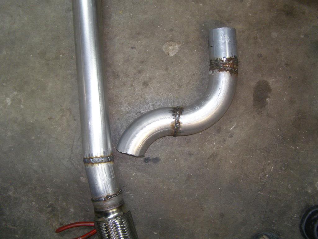
This shows the s-bend that I got rid of. I cut it out and left just the slightest bit of mandrel bend on the existing pipe to set the new angle across the transmission tunnel.I know it looks like a hard angle but the direction change is a radius.
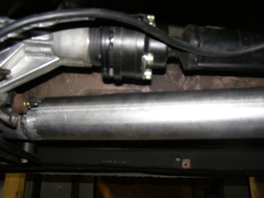
This shows the clearance that I have under the front CV joint on the drive shaft.
This should flow much better than my previous design.
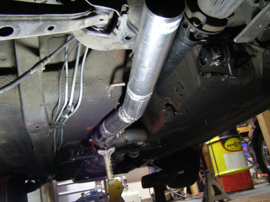
This is my previous exhaust routing. Pay no attention to the fuel lines, they were patch work to get the car running on the cheap when it was NA, I will be running new lines when I build my new fuel system. I forgot how shitty they look, but I didn't want to spend a bunch of time on them when I knew they would be coming out for the turbo project.
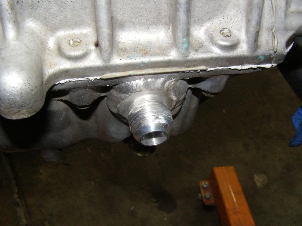
These last 2 shots are of a couple of new fittings. The first are for the breathers, the second shot is my oil return fitting in the pan.
I have also decided to have my manifold and down pipe ceramic coated. I will be pulling everything off tomorrow and sending the manifold and down pipe to Swain for coating.
This shows the s-bend that I got rid of. I cut it out and left just the slightest bit of mandrel bend on the existing pipe to set the new angle across the transmission tunnel.I know it looks like a hard angle but the direction change is a radius.
This shows the clearance that I have under the front CV joint on the drive shaft.
This should flow much better than my previous design.
This is my previous exhaust routing. Pay no attention to the fuel lines, they were patch work to get the car running on the cheap when it was NA, I will be running new lines when I build my new fuel system. I forgot how shitty they look, but I didn't want to spend a bunch of time on them when I knew they would be coming out for the turbo project.
These last 2 shots are of a couple of new fittings. The first are for the breathers, the second shot is my oil return fitting in the pan.
I have also decided to have my manifold and down pipe ceramic coated. I will be pulling everything off tomorrow and sending the manifold and down pipe to Swain for coating.
Reply
0
0
08-03-2010, 05:39 PM
#176
Senior Member
Thread Starter
iTrader: (2)
Join Date: Jan 2010
Location: Denver
Posts: 904
Total Cats: 14
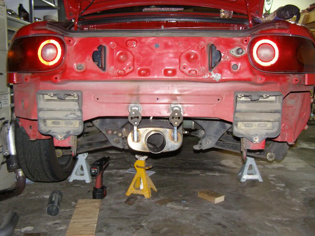
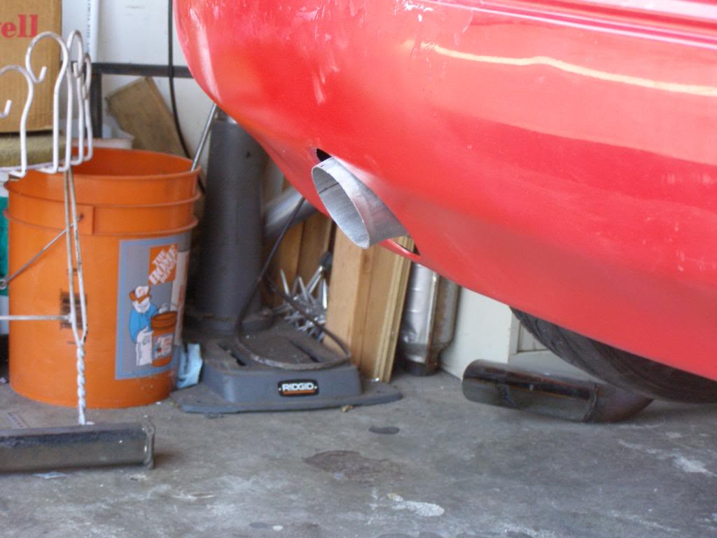
Muffler exit point. The idea was to keep the exhaust as straight as possible so I thought that I would try a middle exit. Here is where I am thus far.
I tried hard to make the big muffler work without the big turns that y8s and brain used. I even looked into exiting through the bumper behind the right rear, but was not happy with how things were looking, so I went with the smaller muffler. The car is a weekend toy, if I find that it is just to loud, I will go with y8s's routing and run the big muffler. Here are a couple of physical size comparison shots.
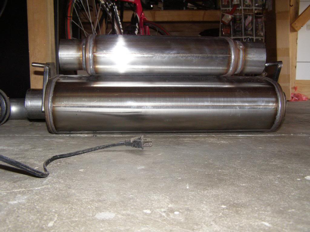
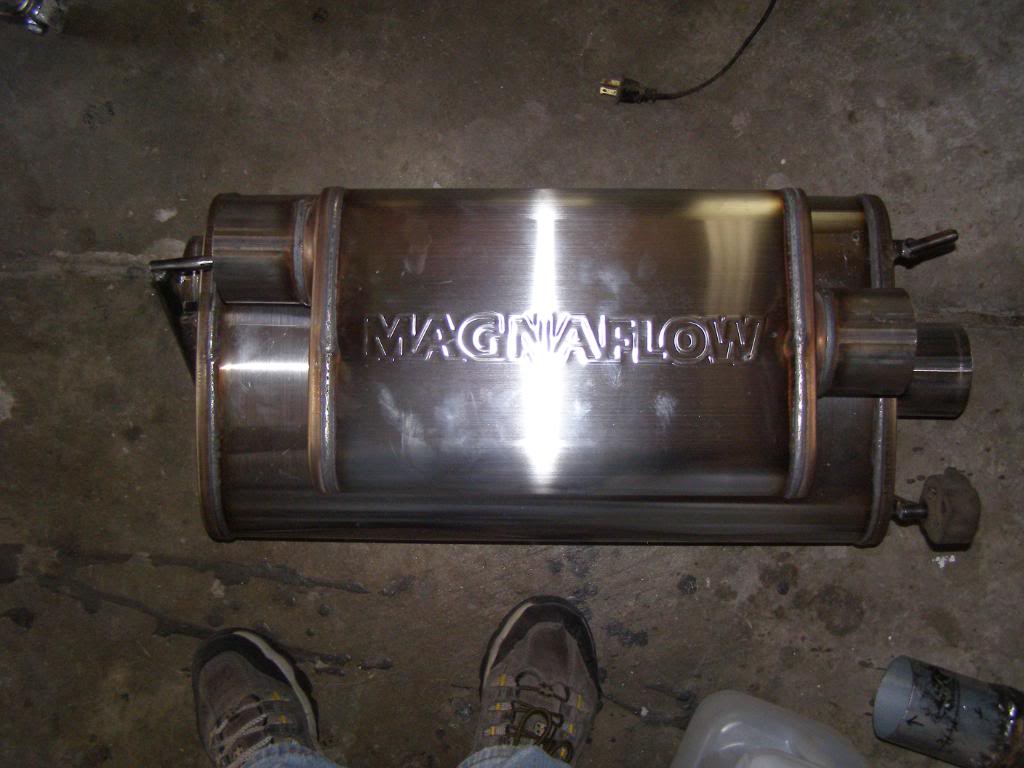
I tried hard to make the big muffler work without the big turns that y8s and brain used. I even looked into exiting through the bumper behind the right rear, but was not happy with how things were looking, so I went with the smaller muffler. The car is a weekend toy, if I find that it is just to loud, I will go with y8s's routing and run the big muffler. Here are a couple of physical size comparison shots.
Reply
0
0
08-09-2010, 06:47 PM
#178
Senior Member
Thread Starter
iTrader: (2)
Join Date: Jan 2010
Location: Denver
Posts: 904
Total Cats: 14
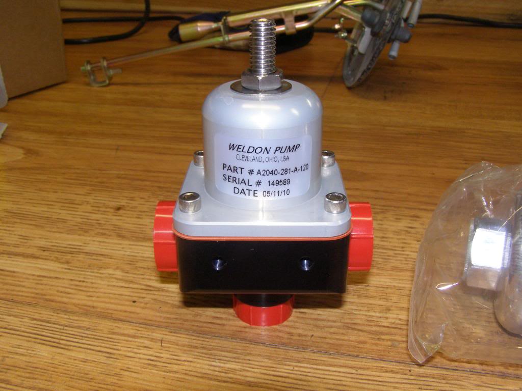
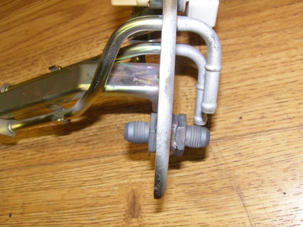
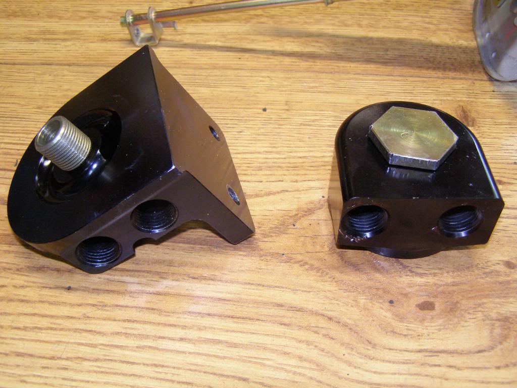
And the build goes on...started accumulating fuel system parts. In the pictures, a weldon 2040 rising rate fuel pressure regulator. A comparo shot, our stock fuel pump compared to a bosch 044. Fuel supply fittings on the gas tank top plate, and finally oil filter relocation blocks.
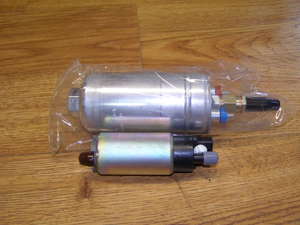
The huge physical size difference between stock and Bosch 044
The huge physical size difference between stock and Bosch 044
Last edited by hingstonwm; 08-09-2010 at 09:54 PM.
Reply
0
0
08-13-2010, 04:45 PM
#179
Senior Member
Thread Starter
iTrader: (2)
Join Date: Jan 2010
Location: Denver
Posts: 904
Total Cats: 14
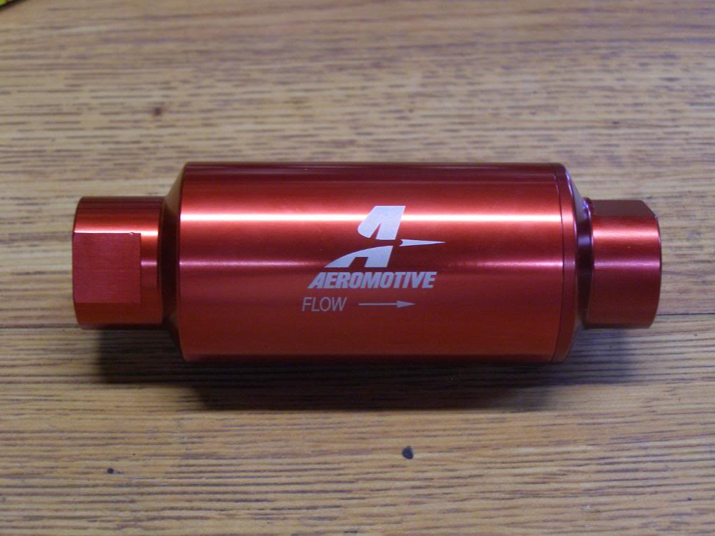
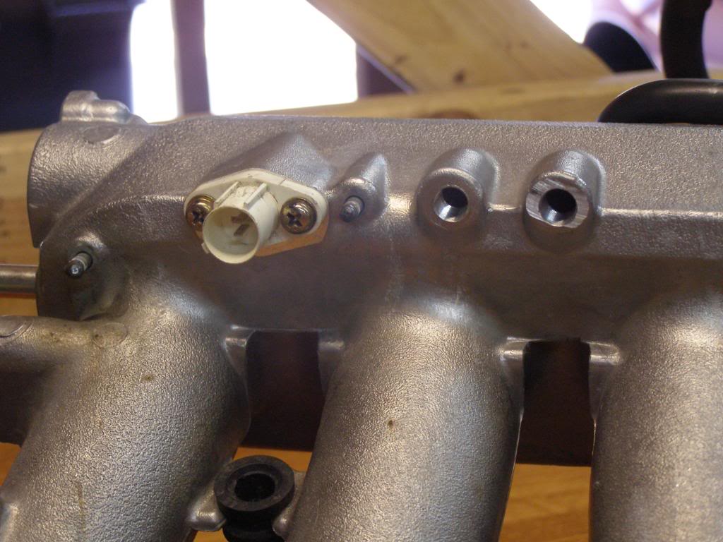
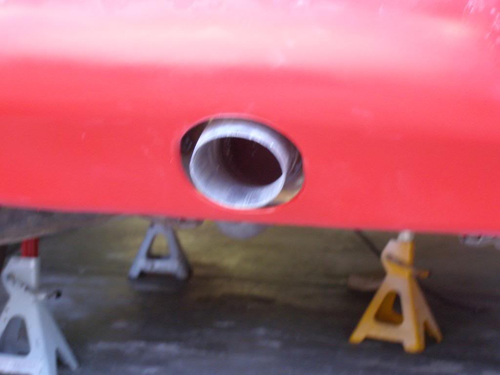
Here are a few more meaningless pics for you guys. The new 100 micron fuel filter, a shot of a couple of the holes that I tapped with 1/8 npt thread in the intake manifold, and a few shots of the exhaust exit from the bumper. Close ups only, as they are sealing the alley behind my garage today.
I used a 5/16 drill bit for the holes, I think next time I may try a 21/64 bit as it was pretty hard to turn the tap as it got close to full depth.
More importantly I received confirmation that my manifold, turbine housing, and down pipe have been delivered to swain, for coating. I should get them back in about 2 1/2 weeks, then I can put everything back on for the last time....I hope!
Here are the pics
Reply
0
0


