f20c engine conversion
 09-02-2010, 09:51 PM
#221
Junior Member

Join Date: Mar 2010
Location: onion city,ca
Posts: 413
Total Cats: 2
As I said in an earlier post I am running a bosh 044 out of tank pump. I located the pump as close to the tank as possible in order to minimize the distance the pump needs to pull fuel. Since I am not running an in tank strainer, I mounted the filter between the pump and tank.
 but i wanted to try out the tig, so i'll take your advice and sand that stuff off. definitely helps, thanks for the detailed writeup. your fuel and turbo lines are dope!

Reply
 0
0

0
09-02-2010, 10:13 PM
#222
Senior Member
Thread Starter
iTrader: (2)

Join Date: Jan 2010
Location: Denver
Posts: 904
Total Cats: 14
Properly welded, there is no chance of a leak. Bulk head fittings are designed to allow a line to terminate on one side of a bulkhead/firewall then start again on the other side. Not really designed for leak proof design, even though there are some bulkhead fittings with seals.
Reply
0
0
09-08-2010, 02:52 AM
#223
Senior Member
Thread Starter
iTrader: (2)
Join Date: Jan 2010
Location: Denver
Posts: 904
Total Cats: 14
Here are a few pictures of the fuel rail, regulator, and a couple of shots of the in tank plumbing as promised.
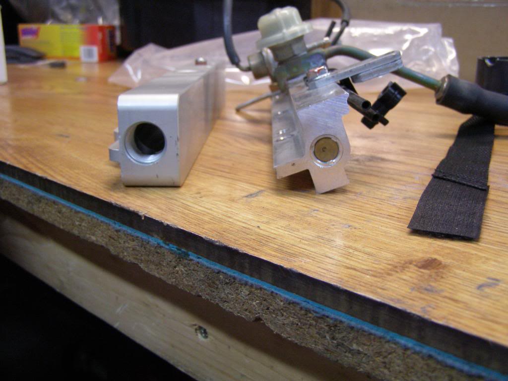
Comparison shot of the new fuel rail compared to the stocker
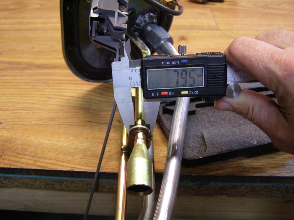
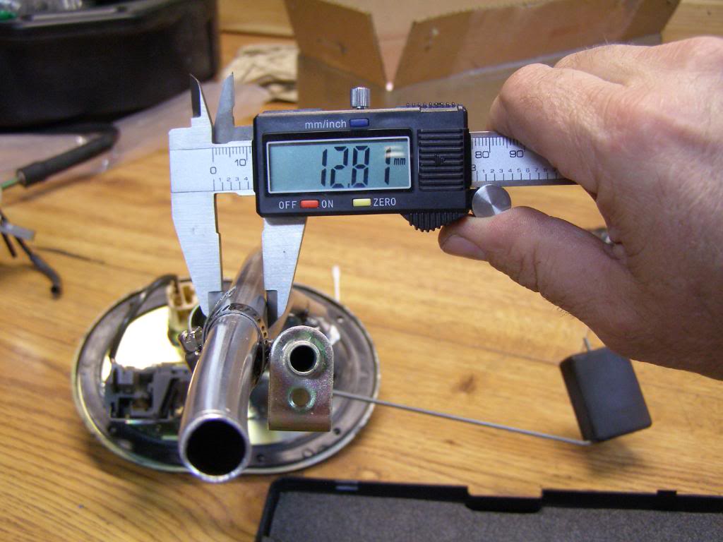
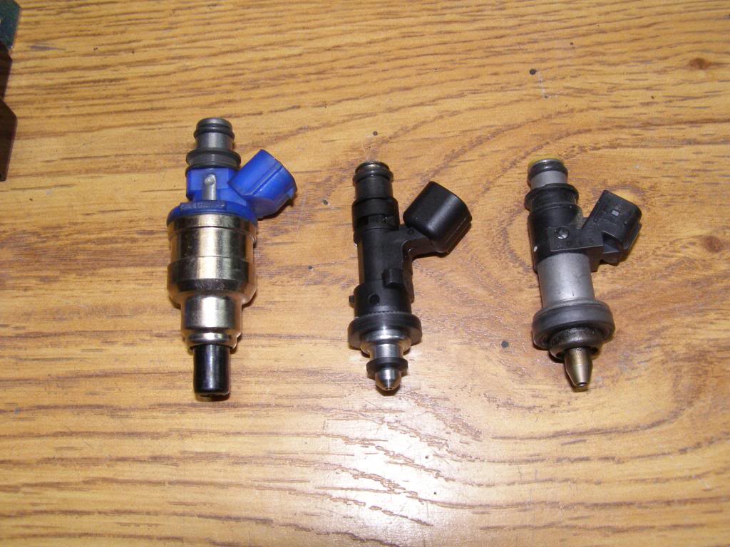
Comparison of the diameter of the stock fuel pick up compared to the new pickup
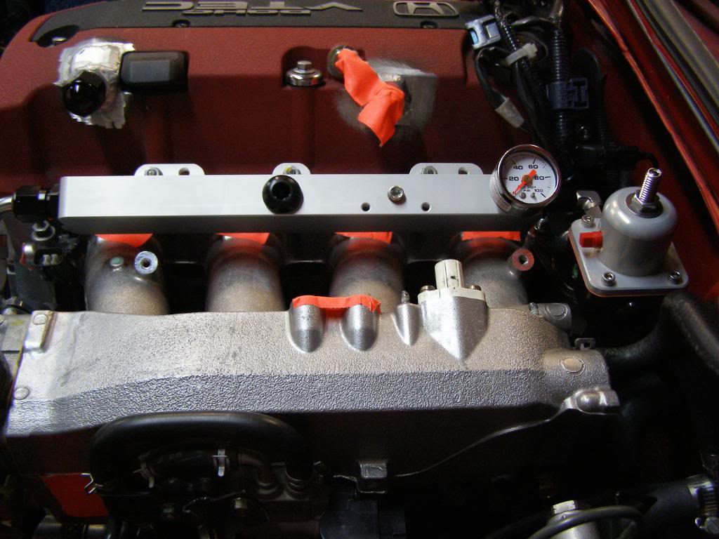
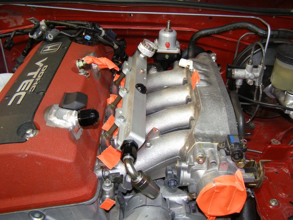
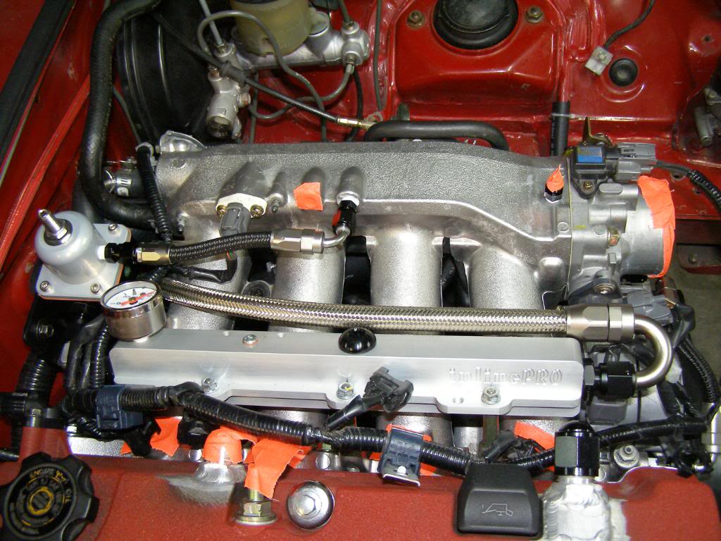
Fuel rail fuel regulator on the engine.

-6 return line and -8 pickup
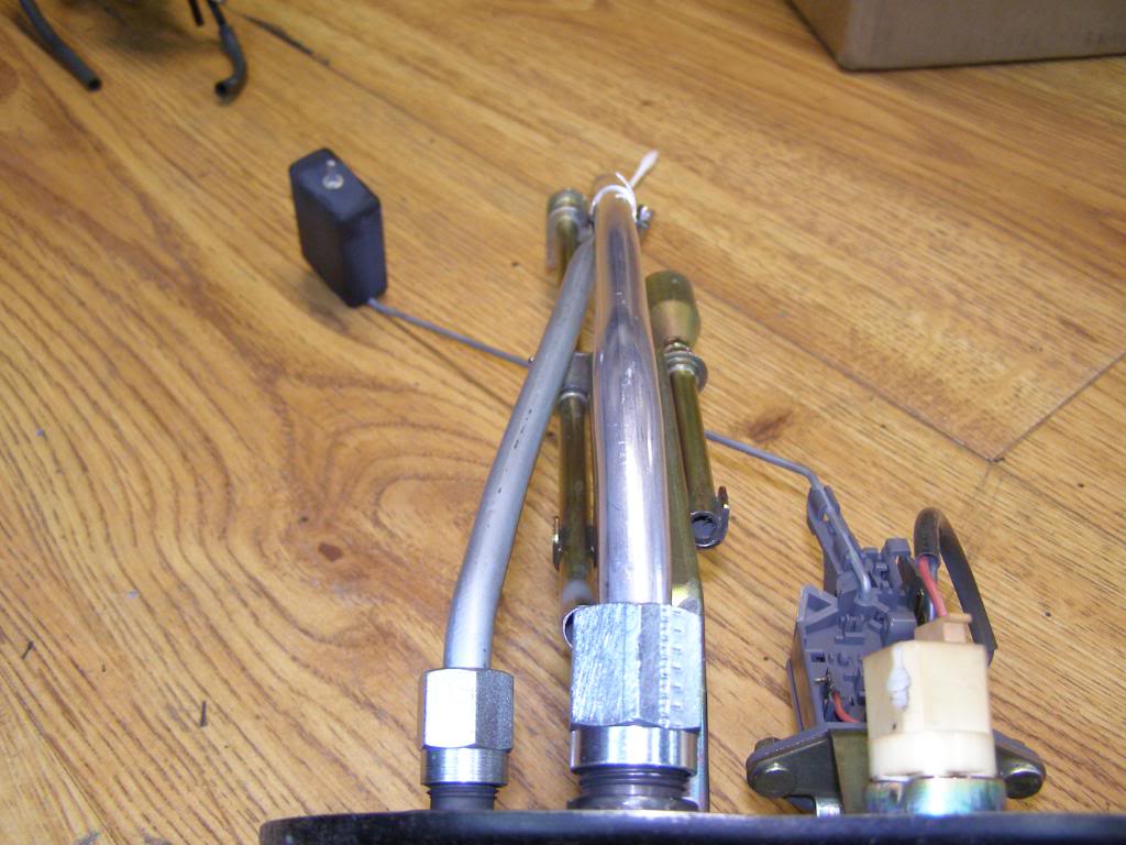
I cut the stock lines out of the fuel tank cover and welded up the holes then installed the -6 and -8 fittings and tubes
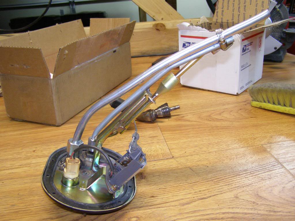
Comparison shot of the new fuel rail compared to the stocker
Comparison of the diameter of the stock fuel pick up compared to the new pickup
Fuel rail fuel regulator on the engine.
-6 return line and -8 pickup
I cut the stock lines out of the fuel tank cover and welded up the holes then installed the -6 and -8 fittings and tubes
Last edited by hingstonwm; 09-11-2010 at 07:22 PM.
Reply
0
0
 09-10-2010, 03:27 AM
#226
Senior Member
Thread Starter
iTrader: (2)
Join Date: Jan 2010
Location: Denver
Posts: 904
Total Cats: 14
So I got a little more work done over the last few days. First off, let me say that I may have thought twice about going with AN lines had I realized what I was getting myself into. Hopefully, the end result will be worth all the effort.
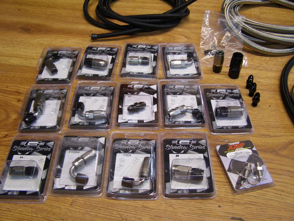
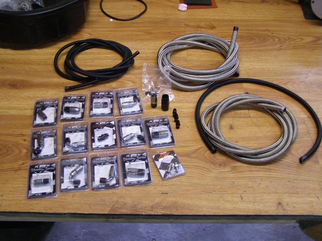
Pics of the latest batch of fittings, the second shot includes -8 and -6 fuel line as well as -4 line for vacuum lines, turbo oil supply, small water lines ect.
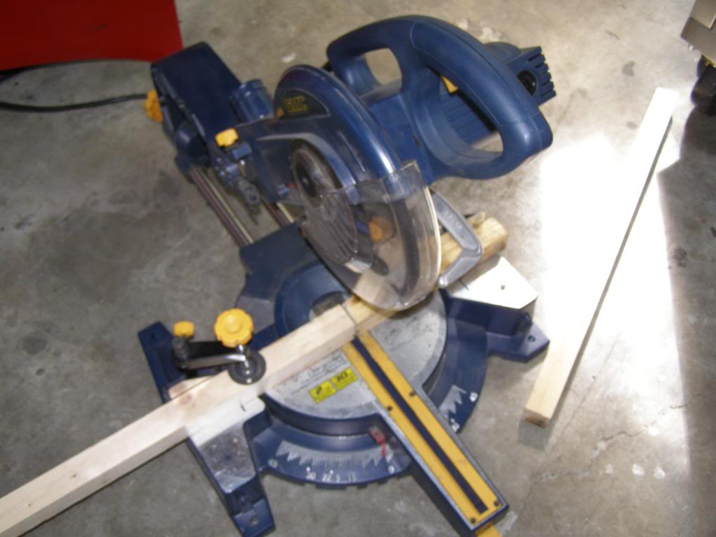
I know there are a lot of different schools of thought on cutting braided line. My solution is an abrasive blade on a miter saw. I set up a fence that moves the lines out further, to ensure clean cuts.
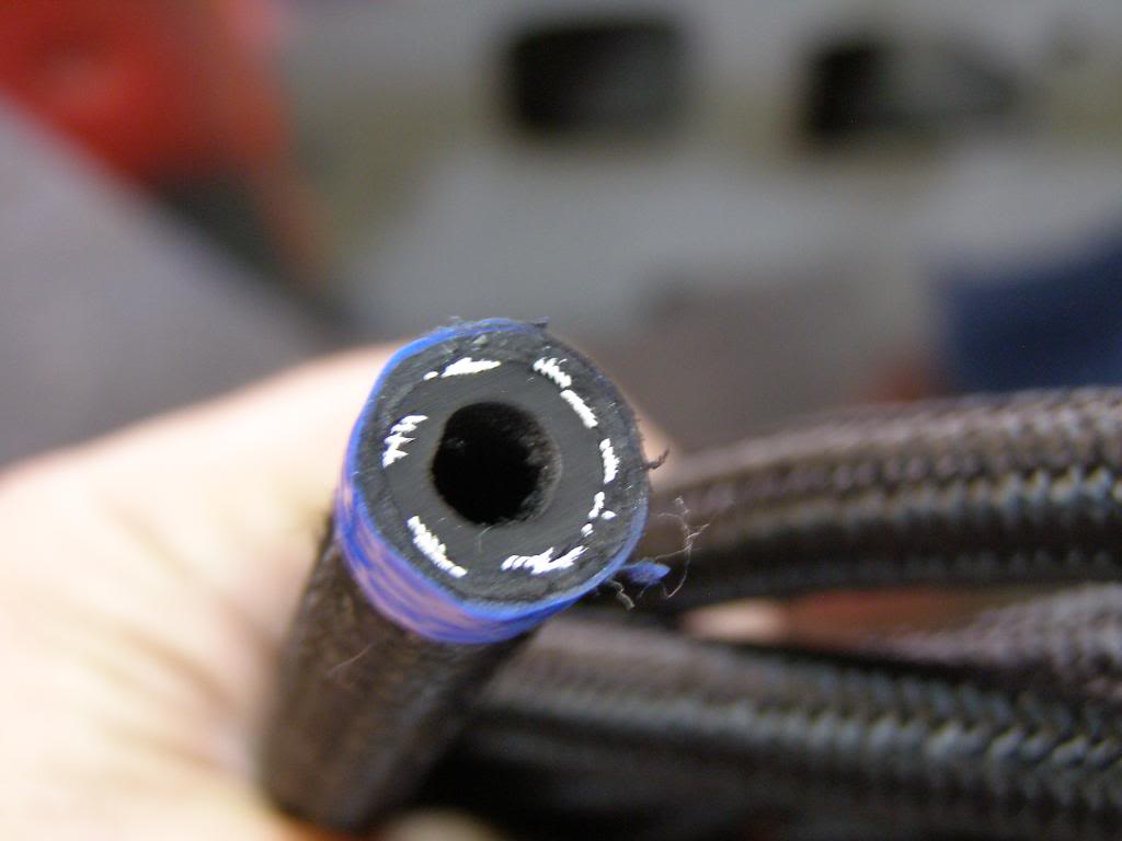
A picture showing the quality of the cut from my set up
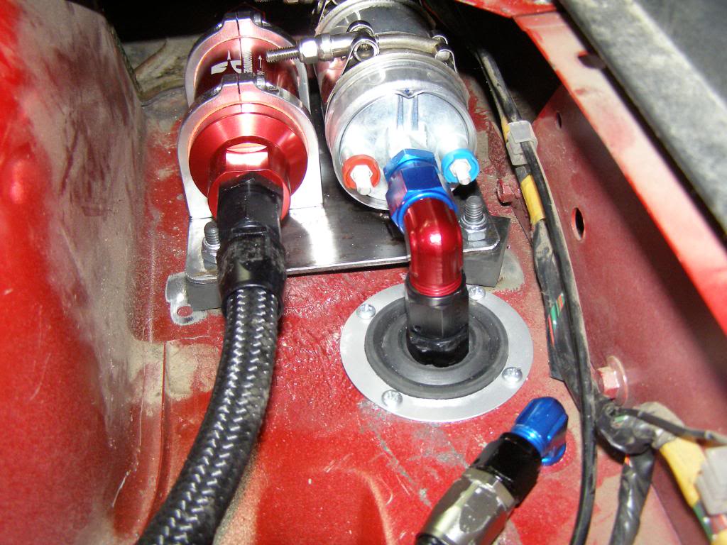
I had to get a little creative getting the supply line through the bulkhead. The fuel pump was mounted a little to low to go straight to a bulkhead
fitting, and I was a bit to tight on space as well. But I think I came up with a pretty decent solution, at least I am happy with it.
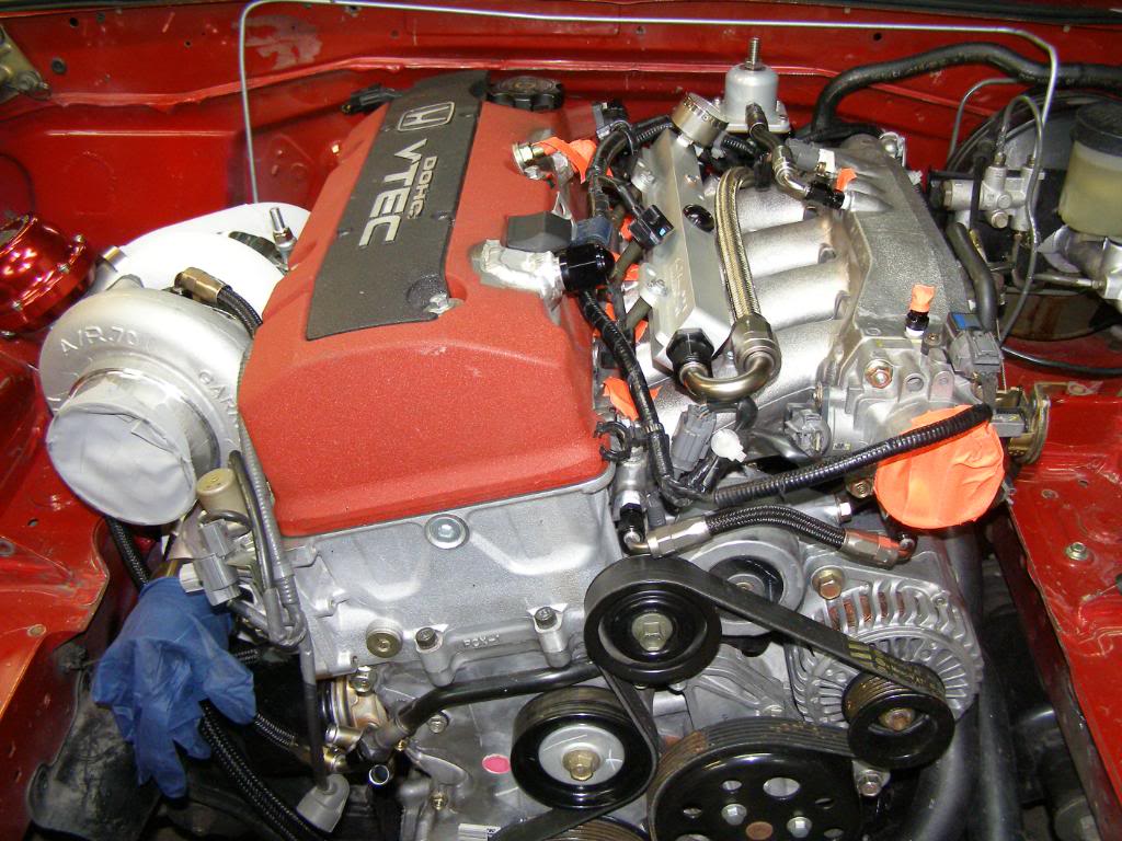
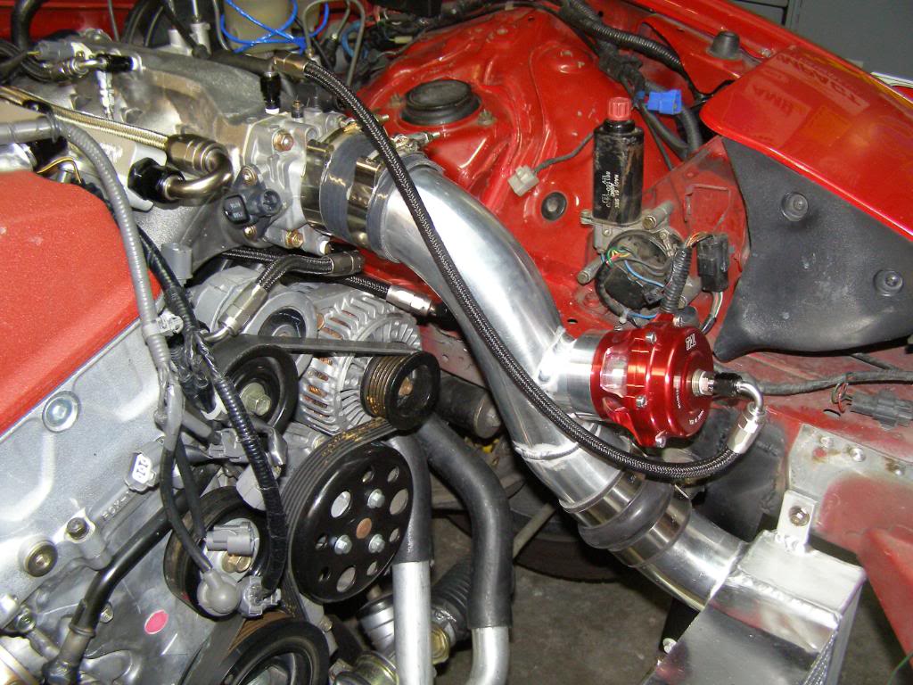
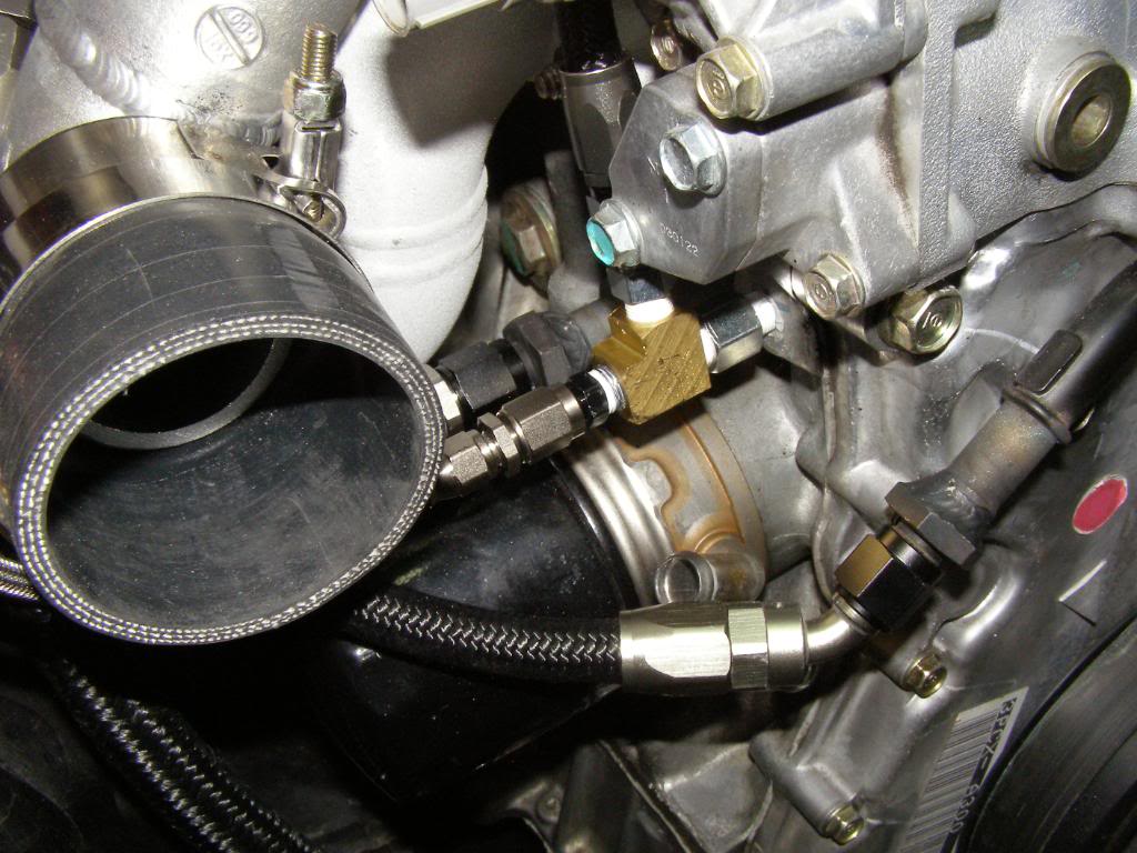
Finally a couple of pictures of the engine, with the supply line, the line from the manifold to the regulator, a small water line from the intake manifold to the throttle body. Some of you may also notice that I tapped the the manifold for a vacuum source behind the throttle body for the blow off valve,you can see the fitting on top of the manifold next to the MAP sensor. I also changed from a 90 degree fitting for the supply line to the fuel rail to a 180 degree. I didn't like the routing I was going to have to use for the 90.
I forgot to take a picture of the oil supply line for the turbo, but I guess if you have seen one supply line you have seen them all.
Pics of the latest batch of fittings, the second shot includes -8 and -6 fuel line as well as -4 line for vacuum lines, turbo oil supply, small water lines ect.
I know there are a lot of different schools of thought on cutting braided line. My solution is an abrasive blade on a miter saw. I set up a fence that moves the lines out further, to ensure clean cuts.
A picture showing the quality of the cut from my set up
I had to get a little creative getting the supply line through the bulkhead. The fuel pump was mounted a little to low to go straight to a bulkhead
fitting, and I was a bit to tight on space as well. But I think I came up with a pretty decent solution, at least I am happy with it.
Finally a couple of pictures of the engine, with the supply line, the line from the manifold to the regulator, a small water line from the intake manifold to the throttle body. Some of you may also notice that I tapped the the manifold for a vacuum source behind the throttle body for the blow off valve,you can see the fitting on top of the manifold next to the MAP sensor. I also changed from a 90 degree fitting for the supply line to the fuel rail to a 180 degree. I didn't like the routing I was going to have to use for the 90.
I forgot to take a picture of the oil supply line for the turbo, but I guess if you have seen one supply line you have seen them all.
Last edited by hingstonwm; 09-23-2010 at 11:12 AM.
Reply
0
0
 09-10-2010, 03:45 PM
#229
Senior Member
Thread Starter
iTrader: (2)
Join Date: Jan 2010
Location: Denver
Posts: 904
Total Cats: 14
^^^Thank You.
I am getting the black braided line from a local speed shop. The black line is available through both summit racing and jegs. I just wanted something other than braided steel, though I did use braided steel for both supply and return lines in the fuel system. I felt the braided steel offered more protection while the lines were under the car.
I also have quite a bit of the braided steel left over so I may use it for the oil cooler and oil relocate that I am planning. I haven't thought that far ahead. I do know that I will be using the black for my breather lines though.
Reply
0
0

 09-20-2010, 02:19 AM
#231
Junior Member
Join Date: Mar 2010
Location: onion city,ca
Posts: 413
Total Cats: 2
thanks for the detailed fuel pickup pics as well as the stainless fuel line pics. i just suddenly got alot more interested in e85 when i discovered the chevron station near where i store my trailer has it now (montague ave, san jose CA). as i understand it, ethanol is hygroscopic, and hence is hard on fuel lines. is this why you used stainless? is it required?
heres kind of a neat turbo catch can using a scavenge pump so the turbo can be mounted low, but i would guess one of these would be easier http://www.optionimports.com/items.asp?Cc=oil_catch_can
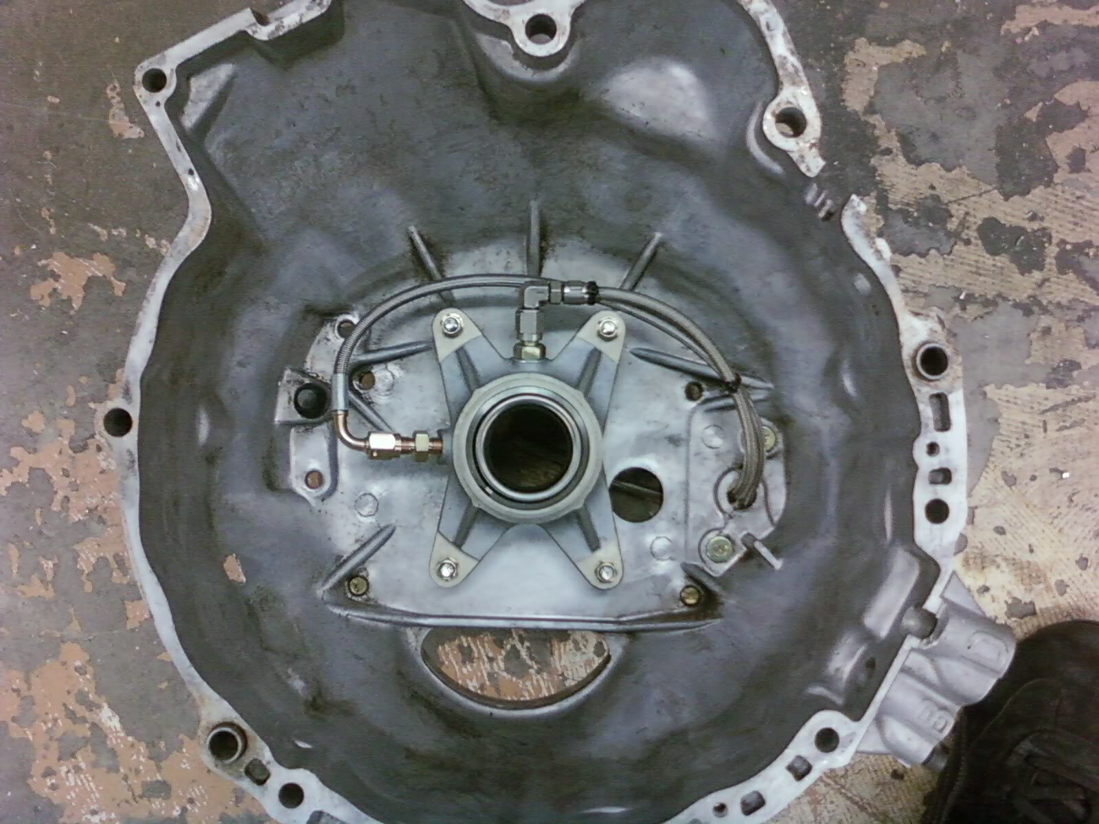
offtopic, but i thought this was trick, tilton hydraulic clutch without the lever:
ref: http://forums.bimmerforums.com/forum....php?t=1272563
heres kind of a neat turbo catch can using a scavenge pump so the turbo can be mounted low, but i would guess one of these would be easier http://www.optionimports.com/items.asp?Cc=oil_catch_can
offtopic, but i thought this was trick, tilton hydraulic clutch without the lever:
ref: http://forums.bimmerforums.com/forum....php?t=1272563
Reply
0
0
09-20-2010, 11:36 AM
#232
Senior Member
Thread Starter
iTrader: (2)
Join Date: Jan 2010
Location: Denver
Posts: 904
Total Cats: 14
I went with the stainless to offer a little more protection to the lines while they are under the car. I could have gone to hard line then back to braided line but the cost savings would have been minimal and more of a pain in the *** to run. As far as being harder on the rubber, I don't have comment on that. I will have to do a little research, and see what is being written. I like the forkless throwout setup.
Reply
0
0
09-23-2010, 04:43 AM
#233
Senior Member
Thread Starter
iTrader: (2)
Join Date: Jan 2010
Location: Denver
Posts: 904
Total Cats: 14
Here is another little update. I am getting close to start up, but noted a couple of items that needed taking care of. I noticed that several of the vband clamps did not seat completely after pulling everything apart and checking level I found several flanges were slightly warped. They are now getting resurfaced flat.
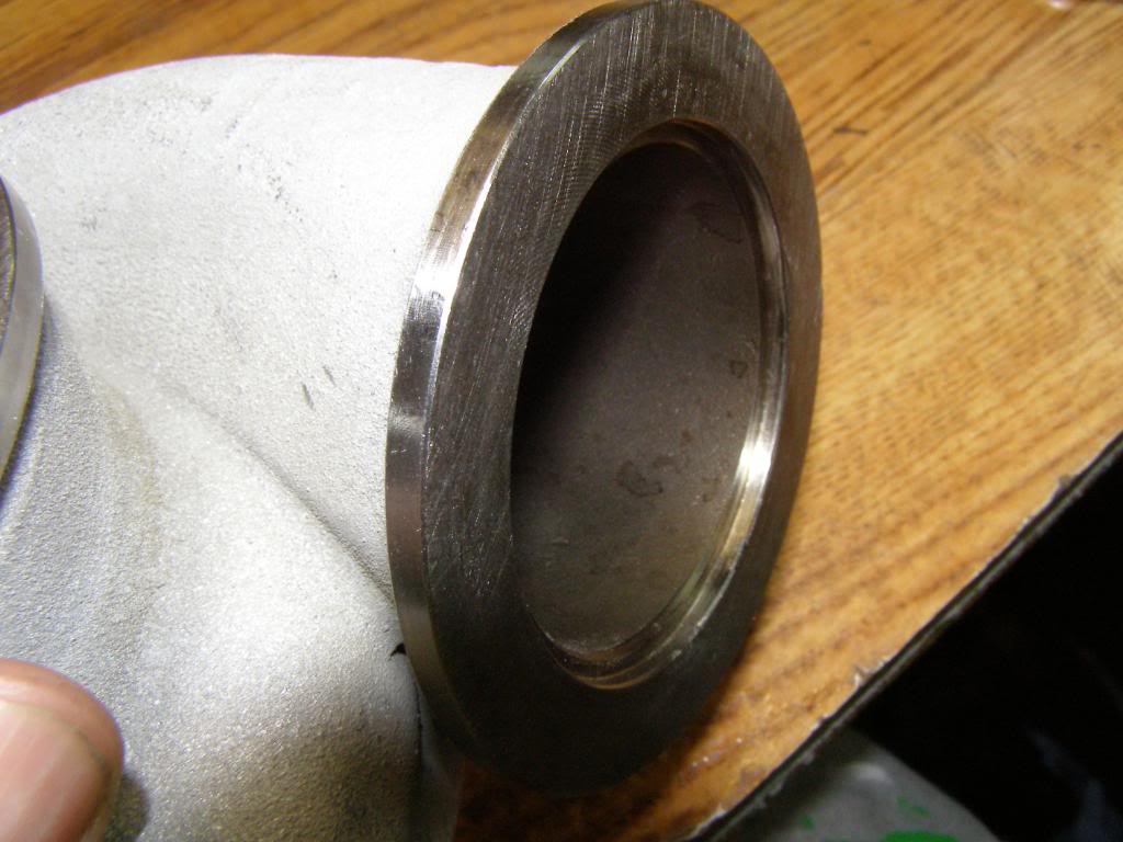
The vband housing at the header to turbine housing is not fitting properly either. The header vband flange has a small ring on it that fits inside a recess in the turbine flange. The problem is the recess is just about 1 mm to small in circumference, which of course means that the joint is going to leak. I will take a dremel tool with a drum sander on it, and open up the recess just enough for proper fit.

The ring
The recess
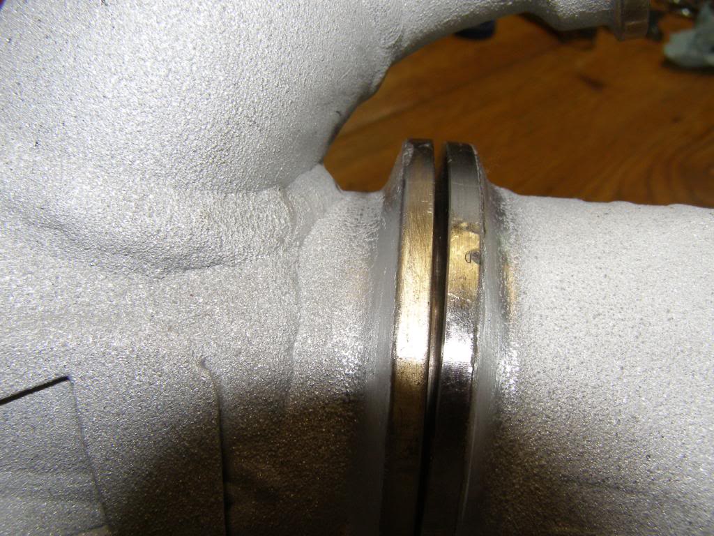
The poor fit and potential leak.
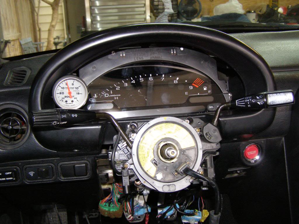
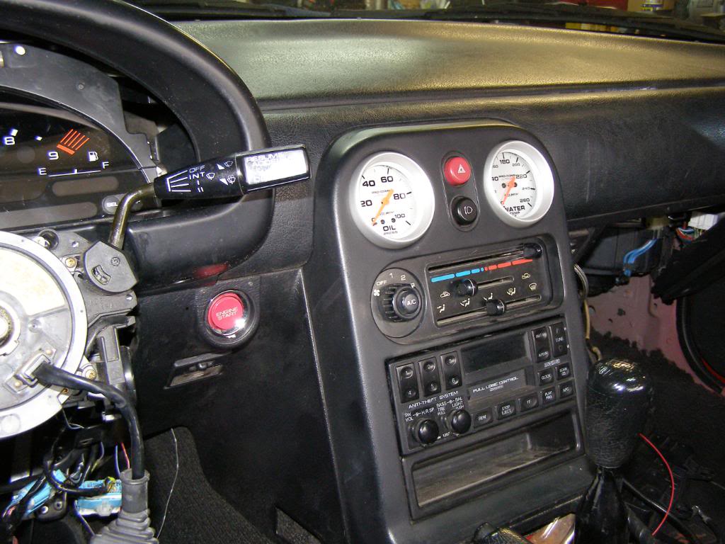
I installed oil pressure, water temp, and boost gauges
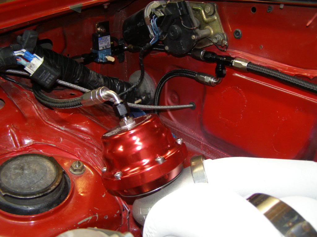
I also plumbed the blow off valve and waste gate.
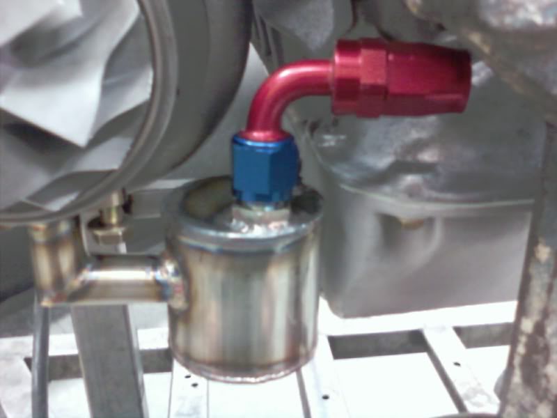
Finally, here is a pic of the fitting coming off the block for the turbo oil supply, and the supply to the oil pressure gauge
The vband housing at the header to turbine housing is not fitting properly either. The header vband flange has a small ring on it that fits inside a recess in the turbine flange. The problem is the recess is just about 1 mm to small in circumference, which of course means that the joint is going to leak. I will take a dremel tool with a drum sander on it, and open up the recess just enough for proper fit.
The ring
The recess
The poor fit and potential leak.
I installed oil pressure, water temp, and boost gauges
I also plumbed the blow off valve and waste gate.
Finally, here is a pic of the fitting coming off the block for the turbo oil supply, and the supply to the oil pressure gauge
Last edited by hingstonwm; 09-23-2010 at 11:08 AM.
Reply
0
0
09-23-2010, 11:05 AM
#235
Senior Member
Thread Starter
iTrader: (2)
Join Date: Jan 2010
Location: Denver
Posts: 904
Total Cats: 14
I bet you could get it to work. You have electronic signal for the spedo, fuel level was plug and play in my conversion. The low fuel warning light, would require you to isolate the right pin from the miata ecu, same with the tach, and water temp. But I bet a motivated guy could get it to work pretty easily.
Reply
0
0
09-23-2010, 01:24 PM
#238
When I did the OBX flanged Vband on mine, I made sure to have it all clamped together through All the welding. It fits perfectly... of course they might have enlarged the tolerances since my friend used them last.
Reply
0
0
 09-23-2010, 01:51 PM
#240
Elite Member
iTrader: (8)

Join Date: Dec 2008
Location: Kingston, Ontario
Posts: 2,910
Total Cats: 51
My Tial didnt have this issue.... strange.
edit... do you have a low pressure 'pusher' pump, or just the external with the new feed in the tank?
edit... do you have a low pressure 'pusher' pump, or just the external with the new feed in the tank?
Last edited by shlammed; 09-23-2010 at 02:05 PM.
Reply
0
0


