f20c engine conversion
 01-10-2010, 06:50 PM
#1
Senior Member
Thread Starter
iTrader: (2)

Join Date: Jan 2010
Location: Denver
Posts: 904
Total Cats: 14
At the request of some members I have started this thread to detail the engine conversion I performed on my 91 Miata.
I have been driving Miatas for the past 10 years and absolutely love the cars. The one short coming as most of us know is power. I thought about FI of the Miata power plant but decided I wanted something different than just another turbo charged Miata. **No offense intended to any of the members of this web site, as I respect all that has been accomplished, and through your work, now realize just what a capable mill the Miata engine is. I thought about the V-8 route but after visiting Miata.net's engine conversion forum, I realized there are quite a few V-8 conversions out there. So many in fact, that there are 3 or 4 companies that make kits for V-8 conversions. No thank you, I wanted something original. That is what led me to the Honda f20c; no kit for this conversion I would need to do it all on my own!
I bought my 91 on eBay for $1300 with a hardtop; it was a non-running automatic car. I got the car running and put a 5spd in it and drove it for 5 years before starting the conversion.
Now, onto the fun stuff!! The first thing needed after brainstorming the project? An engine and transmission of course! After countless hours of watching eBay and Craigslist I settled on an engine and transmission located in Las Vegas. The carfax stated salvage title issued at 10, 358 miles. Being a student and cash strapped, I decided to drive out and pick the engine up myself. The transportation of choice? Not my truck; it uses too much gas, nope I used my trusty old 1988 Acura Legend; which has since been sold to a friend. Take out the passenger seat and off to Vegas, hell its only 11 hours one way and I had the whole weekend off. The result, mission accomplished transmission in the back seat, engine on the floor. Vegas and back in 26 clock hours!

Reply
 0
0

0
01-10-2010, 06:58 PM
#2
Senior Member
Thread Starter
iTrader: (2)
Join Date: Jan 2010
Location: Denver
Posts: 904
Total Cats: 14
Here is the engine and transmission. the engine is taller and about 1.5 inches longer than the stock engine. Aluminum block and head, I never weighed it but my car only weighs 2400 pounds with me in it, and the hardtop.
[IMG] [/IMG][
IMG]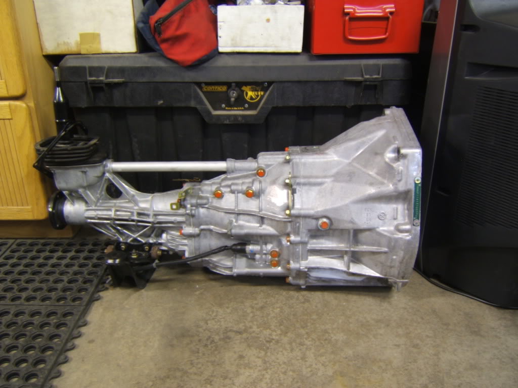 [/IMG]
[IMG]
[/IMG][IMG]
[/IMG]
Reply
0
0


 01-10-2010, 07:28 PM
#5

Nice man, so is it in the car now? Any pics of the car together? I'm sure you've probably seen this thread but it's definitely an interesting read: S2KI - S2000 Forums -> Miata + S2000 = M2000?
Reply
0
0
01-10-2010, 08:48 PM
#6
Senior Member
Thread Starter
iTrader: (2)
Join Date: Jan 2010
Location: Denver
Posts: 904
Total Cats: 14
[/QUOTE]I'm sure you've probably seen this thread but it's definitely an interesting read: S2KI - S2000 Forums -> Miata + S2000 = M2000?[/QUOTE]
Yes, I looked at his build. The paint job is incredible, but to me the rest of his build left me saying why didn't they do "X". I must admit though, they did a good job documenting the build, which gave me insight on my solutions to engineering obstacles
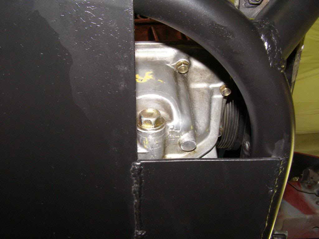
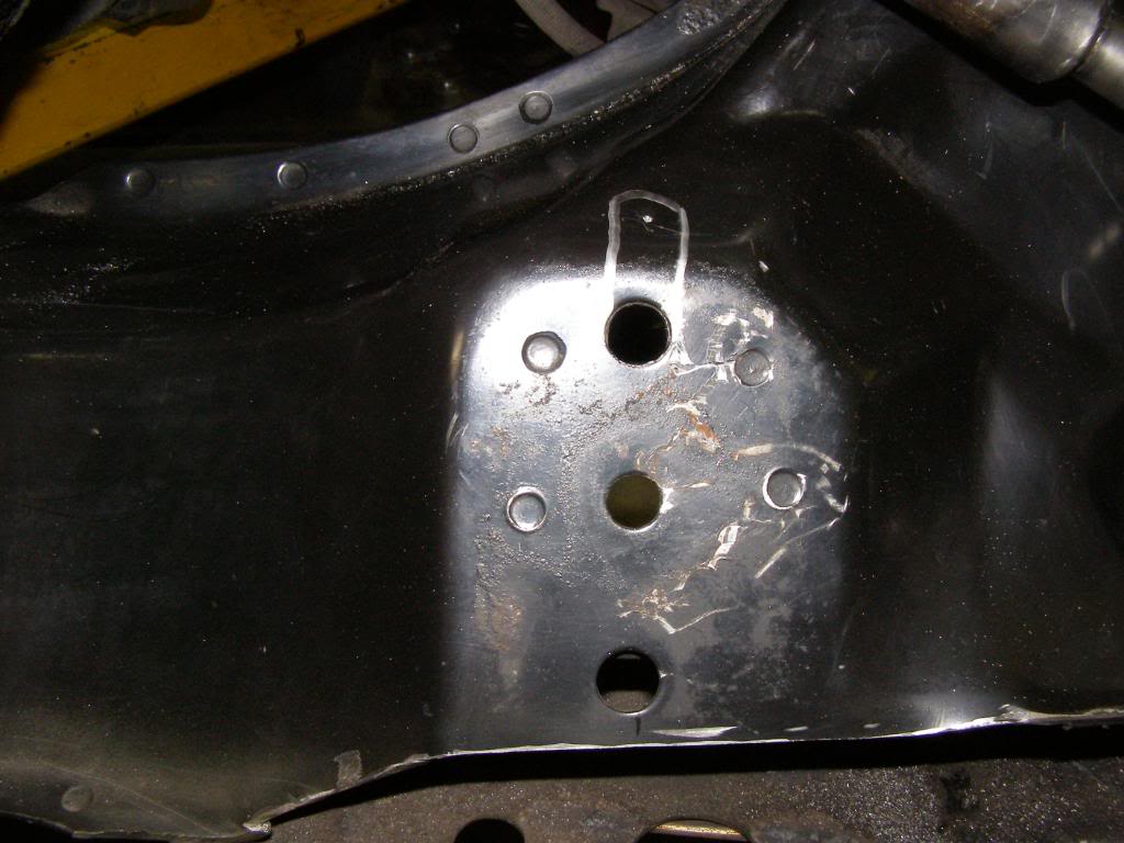
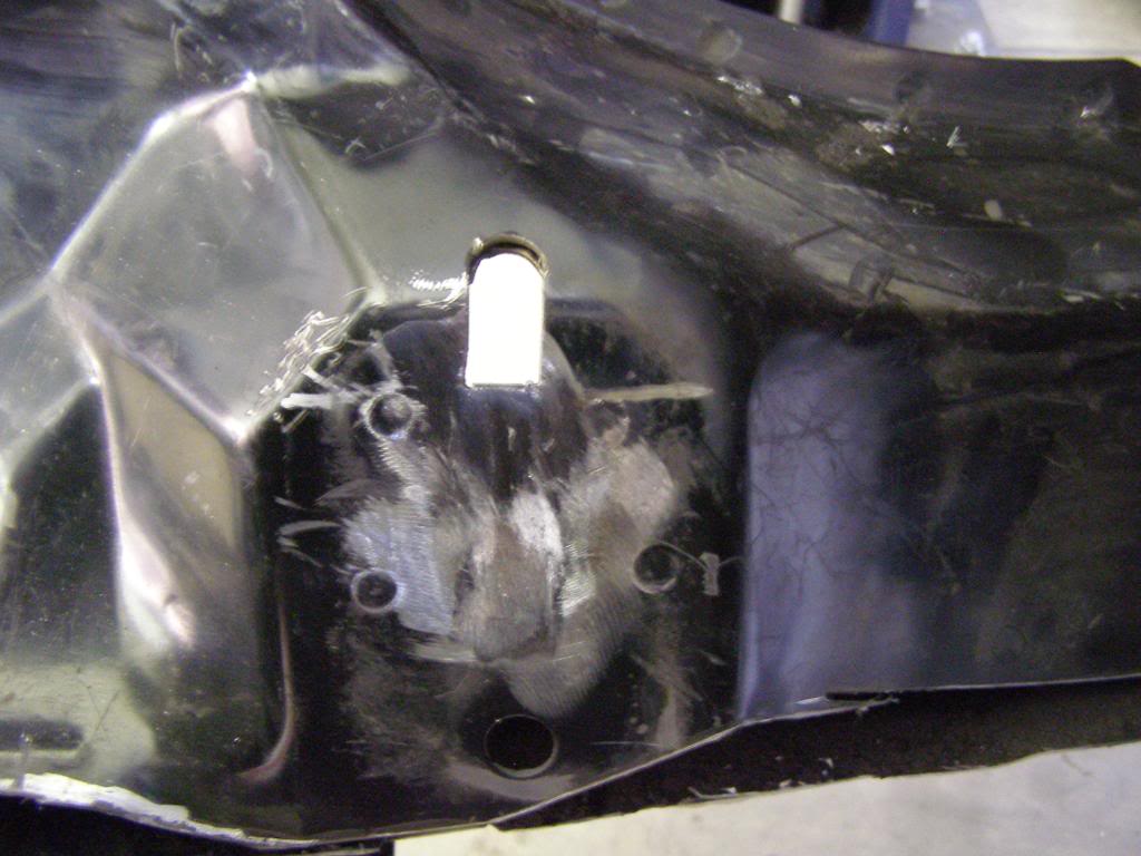
Here is an example of what I am talking about. Because the rack has to be moved due to the front sump oil pan, a new rack mount must be fabricated. The first picture is their solution, the second picture is mine. I show this not to bash his build but to illustrate how his willingness to share allowed me to critique, and come up with what I consider a better solution. It is always easier to come up with good ideas after you have seen the problem!
Their solution to rack mount (I don't care for all the shims)
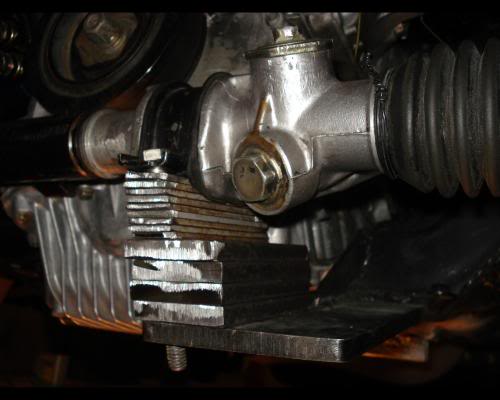
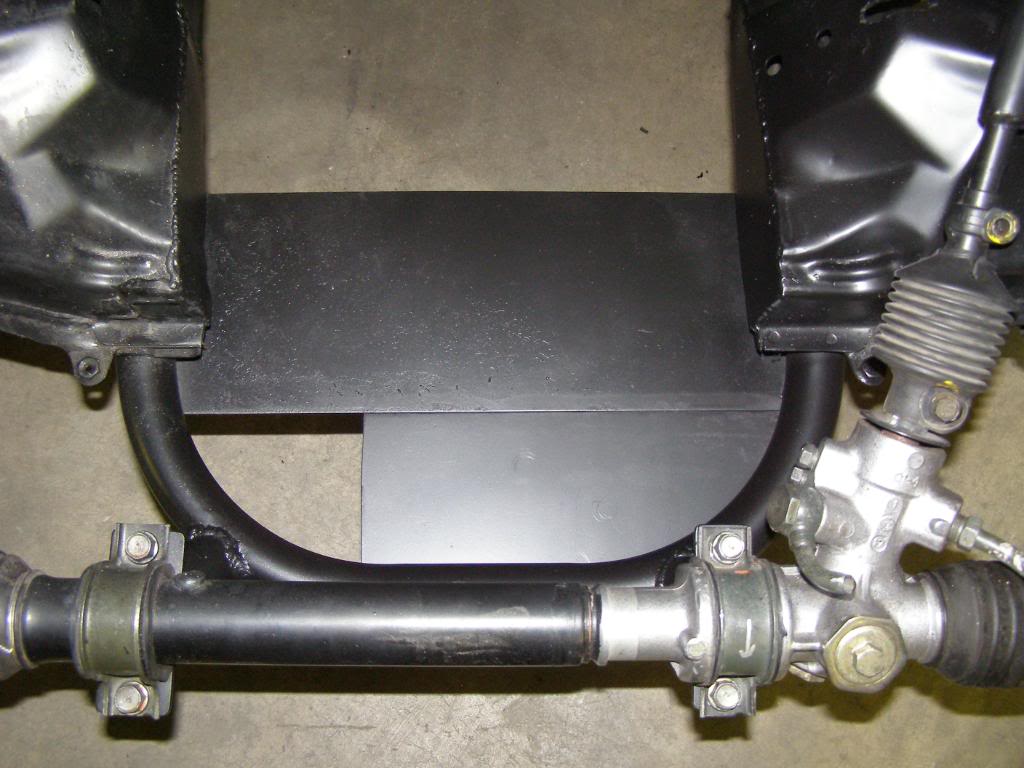
My solution (simple and strong!)
Yes, I looked at his build. The paint job is incredible, but to me the rest of his build left me saying why didn't they do "X". I must admit though, they did a good job documenting the build, which gave me insight on my solutions to engineering obstacles
Here is an example of what I am talking about. Because the rack has to be moved due to the front sump oil pan, a new rack mount must be fabricated. The first picture is their solution, the second picture is mine. I show this not to bash his build but to illustrate how his willingness to share allowed me to critique, and come up with what I consider a better solution. It is always easier to come up with good ideas after you have seen the problem!
Their solution to rack mount (I don't care for all the shims)
My solution (simple and strong!)
Last edited by hingstonwm; 01-10-2010 at 10:36 PM.
Reply
0
0


 01-10-2010, 09:54 PM
#9
Senior Member
Thread Starter
iTrader: (2)
Join Date: Jan 2010
Location: Denver
Posts: 904
Total Cats: 14
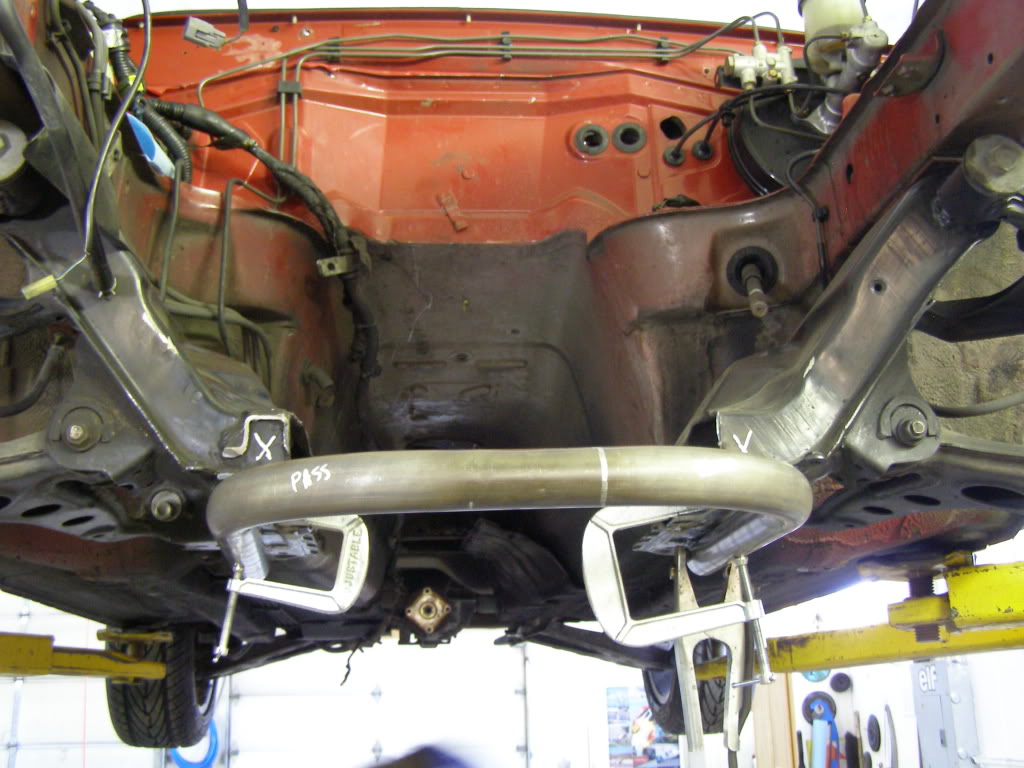
The first issue, how do you fit a front sump engine into a k-member designed for a rear sump engine? Answer, heavy modification.
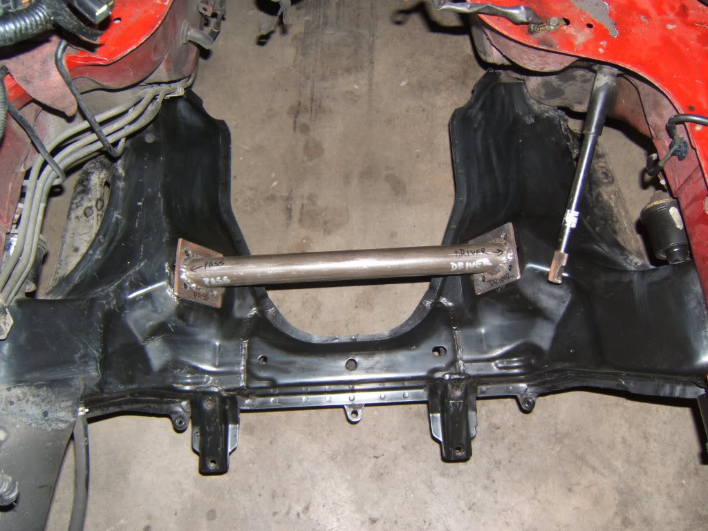
Index bar, this makes sure that there is no movement of the separate sections of k-member after the center section is cut out to make room for the front sump.
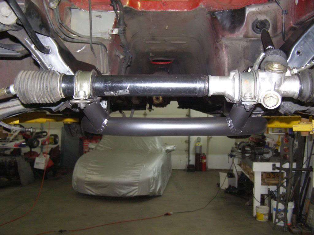
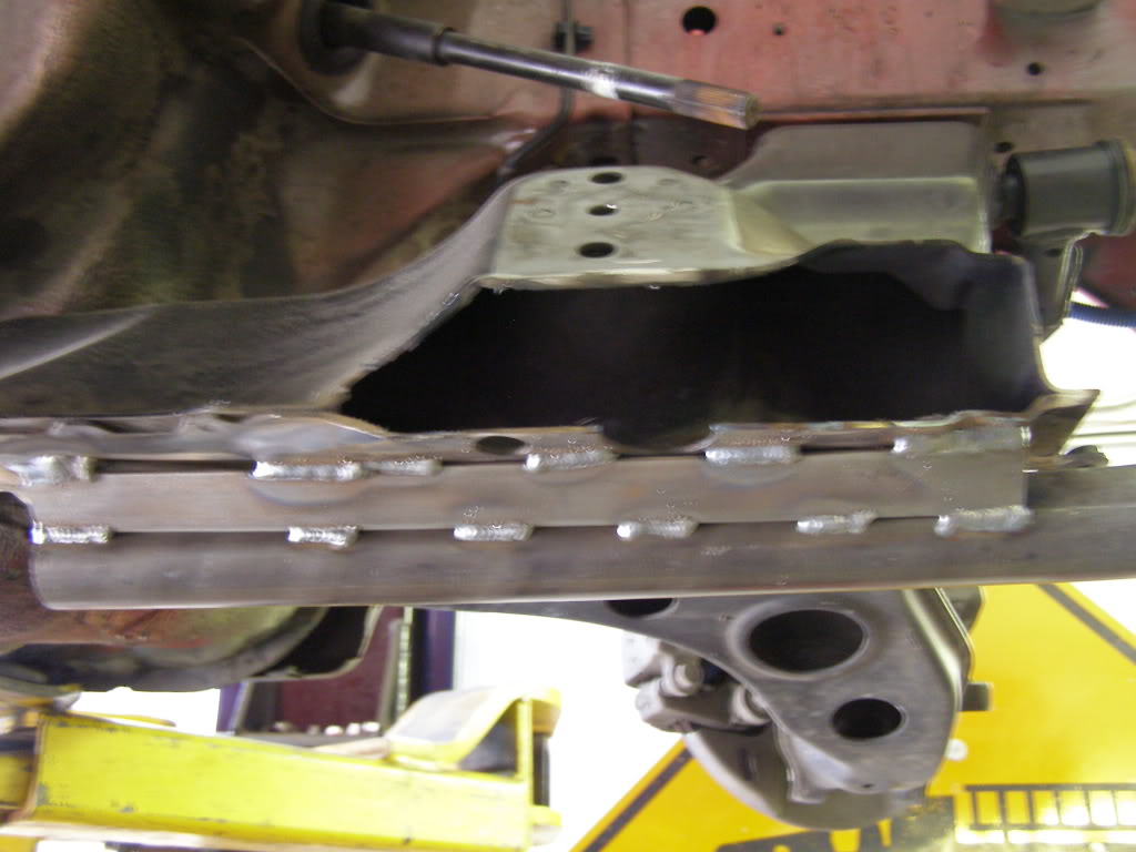
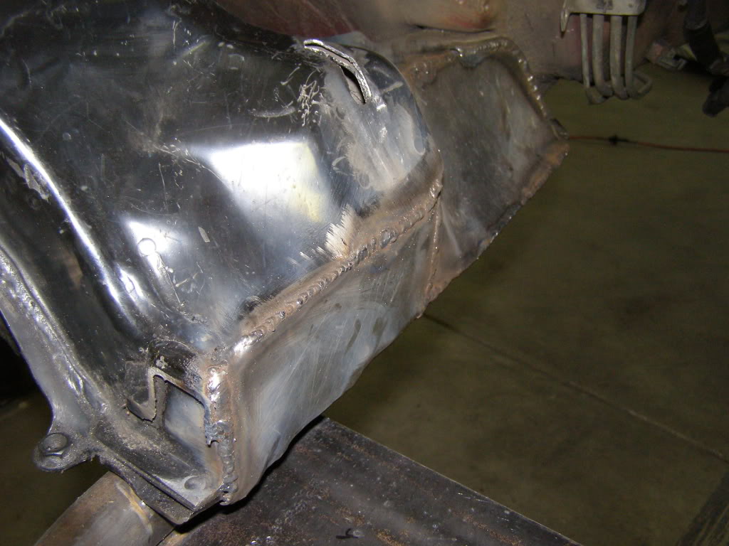
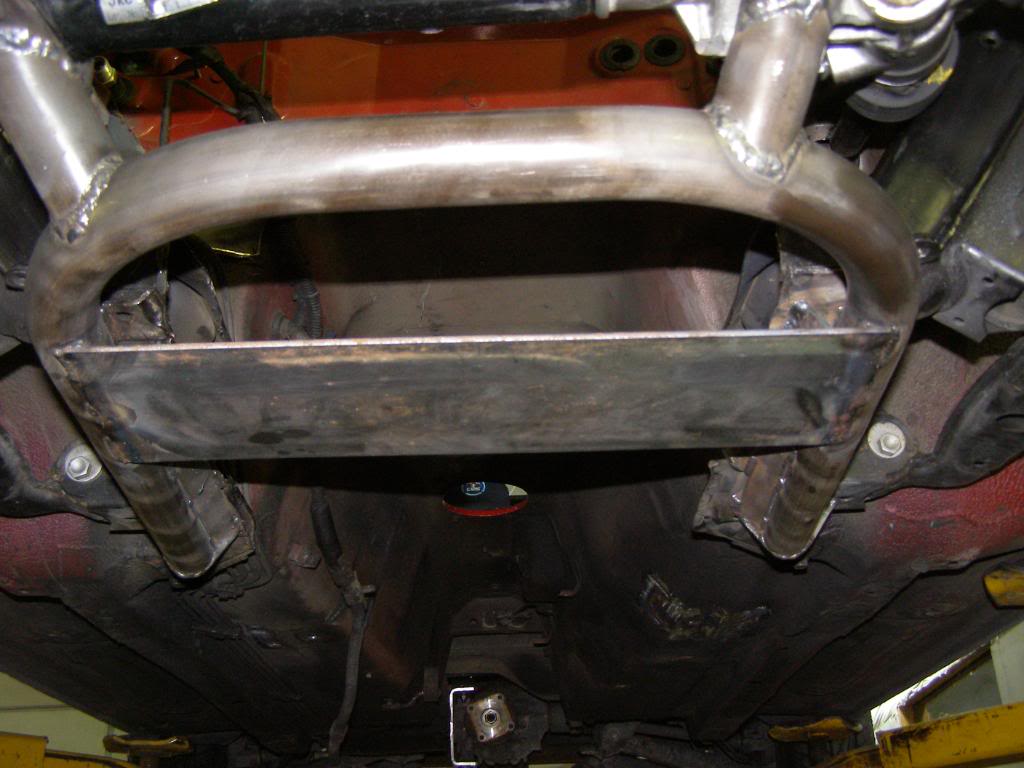
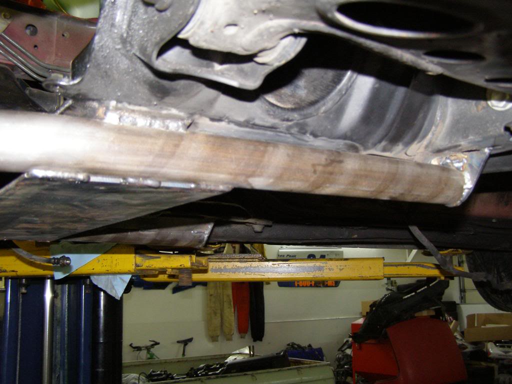
The k-member is a hybrid using factory part that is cut then reinforced with 1.5 inch .120 wall DOM tubing. Besides strength the tubing forms the frame work for the skid plate that protects the oil pan. The lowest point of the car is the bottom of the tubing which is .75 inches lower than the oil pan. Additionally a relief was fabbed into the right side k-member to create extra clearance for the exhaust. The tubing also serves as a mounting point for the steering rack (shown in an earlier post)
Drain plug opening in skid plate (1/8” steel plate)
Tubing in place waiting to be tacked
Reinforcing for the tube frame
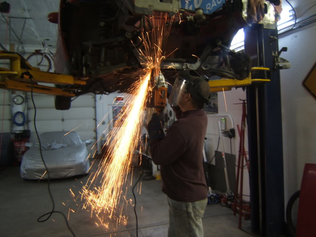
Going in, first sparks!

With this out there is room for the oil pan
Boxed in cuts k-member note the elongated slot for the engine mount stud. Doing this keeps you from fighting to get the engine home
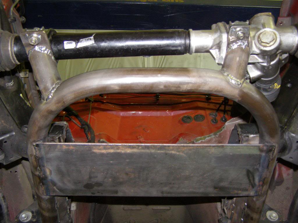
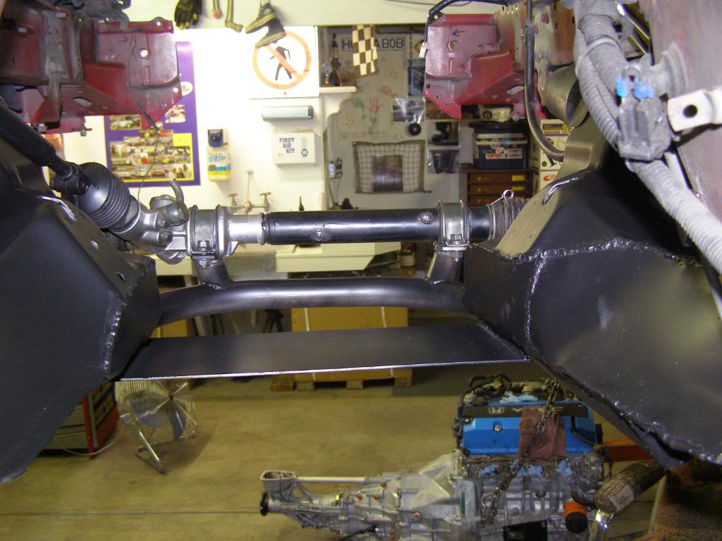
Look closely and you will notice that the rack is not mounted square OOOOPS. I measured off of the engine instead of the face of the k-member when I mounted this the first time. (the oil pan is not in a flat plane across its face). Had to do it a second time, this kind of stuff happens once in a while. At least I noticed it before I tried to drive the car.
A work in progress
I moved the mounting point up to the top of the landing for the engine mounts, this needed to be done in order to use stock miata engine mount rubbers.
While I was doing this I had a huge brainstorm!! We have all struggled at one time or another when replacing a Miata engine with getting the stud on the engine mount into the hole in the k-member then getting the other side to fall into the slot. Well if you elongate the holes so they day light on the horizontal plane the problem is solved. I like to work smarter not harder
A couple of shots of the completed k-member

Notice the relief on the right side of k-member for exhaust clearance
Will have more later!! Any thoughts or comments are welcome.
Index bar, this makes sure that there is no movement of the separate sections of k-member after the center section is cut out to make room for the front sump.
The k-member is a hybrid using factory part that is cut then reinforced with 1.5 inch .120 wall DOM tubing. Besides strength the tubing forms the frame work for the skid plate that protects the oil pan. The lowest point of the car is the bottom of the tubing which is .75 inches lower than the oil pan. Additionally a relief was fabbed into the right side k-member to create extra clearance for the exhaust. The tubing also serves as a mounting point for the steering rack (shown in an earlier post)
Drain plug opening in skid plate (1/8” steel plate)
Tubing in place waiting to be tacked
Reinforcing for the tube frame
Going in, first sparks!
With this out there is room for the oil pan
Boxed in cuts k-member note the elongated slot for the engine mount stud. Doing this keeps you from fighting to get the engine home
Look closely and you will notice that the rack is not mounted square OOOOPS. I measured off of the engine instead of the face of the k-member when I mounted this the first time. (the oil pan is not in a flat plane across its face). Had to do it a second time, this kind of stuff happens once in a while. At least I noticed it before I tried to drive the car.
A work in progress
I moved the mounting point up to the top of the landing for the engine mounts, this needed to be done in order to use stock miata engine mount rubbers.
While I was doing this I had a huge brainstorm!! We have all struggled at one time or another when replacing a Miata engine with getting the stud on the engine mount into the hole in the k-member then getting the other side to fall into the slot. Well if you elongate the holes so they day light on the horizontal plane the problem is solved. I like to work smarter not harder
A couple of shots of the completed k-member
Notice the relief on the right side of k-member for exhaust clearance
Will have more later!! Any thoughts or comments are welcome.
Last edited by hingstonwm; 01-10-2010 at 10:13 PM.
Reply
0
0
01-10-2010, 10:21 PM
#11
Cpt. Slow

iTrader: (25)
Join Date: Oct 2005
Location: Oregon City, OR
Posts: 14,175
Total Cats: 1,129
Nope. There's a picture somewhere of him welding them all together and painting them black. So that's more or less his final "design". A big block of Aluminum with two holes in it would of been much better in my mind, if you're not willing to use hingstonwm's method.
Reply
0
0
01-10-2010, 10:24 PM
#12
Senior Member
Thread Starter
iTrader: (2)
Join Date: Jan 2010
Location: Denver
Posts: 904
Total Cats: 14
kotomile you are right. when I first noticed it I thought, how in the hell did I get that so wrong and not notice it? Then once I thought about it I had a  moment.
I will support the engine and drop the k member when I do the plumbing for the oil return line on the turbo. When I have it down I will pull the control arms, and have it sand blasted and powder coated. I plan on doing another one of these conversions and leaving the engine normally aspirated and using it as a daily driver. When the time comes for that conversion I will most likely purchase a FM tubular k-member to use on the hot rod and put this k-member on the daily driver.
moment.I will support the engine and drop the k member when I do the plumbing for the oil return line on the turbo. When I have it down I will pull the control arms, and have it sand blasted and powder coated. I plan on doing another one of these conversions and leaving the engine normally aspirated and using it as a daily driver. When the time comes for that conversion I will most likely purchase a FM tubular k-member to use on the hot rod and put this k-member on the daily driver.
Reply
0
0
01-10-2010, 10:42 PM
#15
Senior Member
iTrader: (8)
Join Date: Mar 2006
Location: Indianapolis, IN
Posts: 1,105
Total Cats: 229
You have probably already thought of this, but make sure you get some heat shielding over the wiring here since the exhaust is running on the passenger side instead of the driver side. Fantastic work so far, you make me want to get my welder back now from my buddy who has been borrowing it for a few months just so I can learn how to use it.
Reply
0
0
01-10-2010, 11:03 PM
#17
Senior Member
Thread Starter
iTrader: (2)
Join Date: Jan 2010
Location: Denver
Posts: 904
Total Cats: 14
[QUOTE=boileralum;506548]You have probably already thought of this, but make sure you get some heat shielding over the wiring here since the exhaust is running on the passenger side instead of the driver side. Fantastic work so far, you make me want to get my welder back now from my buddy who has been borrowing it for a few months just so I can learn how to use it.
On a side note could you post some pics of your wheel and tire package? I am thinking about going with the same setup on my car
Already taken care of. I will get into the wiring in a later post! Oh yeah and the movemnet of all the fuel lines to the other side as well.
On a side note could you post some pics of your wheel and tire package? I am thinking about going with the same setup on my car
Already taken care of. I will get into the wiring in a later post! Oh yeah and the movemnet of all the fuel lines to the other side as well.
Last edited by hingstonwm; 01-11-2010 at 01:14 AM.
Reply
0
0


