Faelflora breaks his promise, time to part out car. GIT THE SAWZALL!

 02-05-2011, 01:23 PM
#462

Considering .040 is greater then most OEM applications, I'd say its more then enough.
Without checking output voltage on the coil, I'm not sure how it could be tested. Hopefully the Brain or one of the other smarter guys in here can shed some light on this in a "coils for dummies" format (as I'm also curious about it).
Without checking output voltage on the coil, I'm not sure how it could be tested. Hopefully the Brain or one of the other smarter guys in here can shed some light on this in a "coils for dummies" format (as I'm also curious about it).

Reply
 0
0

0
02-06-2011, 07:04 PM
#464
Elite Member
Thread Starter
iTrader: (2)

Join Date: Jan 2007
Location: Los Angeles, CA
Posts: 8,682
Total Cats: 130
Spent a few hours working on the coils today.
I had to run a few more wires to the hydra- signal ground and two signal wires for the additional coils. I used some canare star quad I have from my studio. The signal wires are twisted inside the sheath and it is foil shielded. Nice cable albeit somewhat difficult to work with.
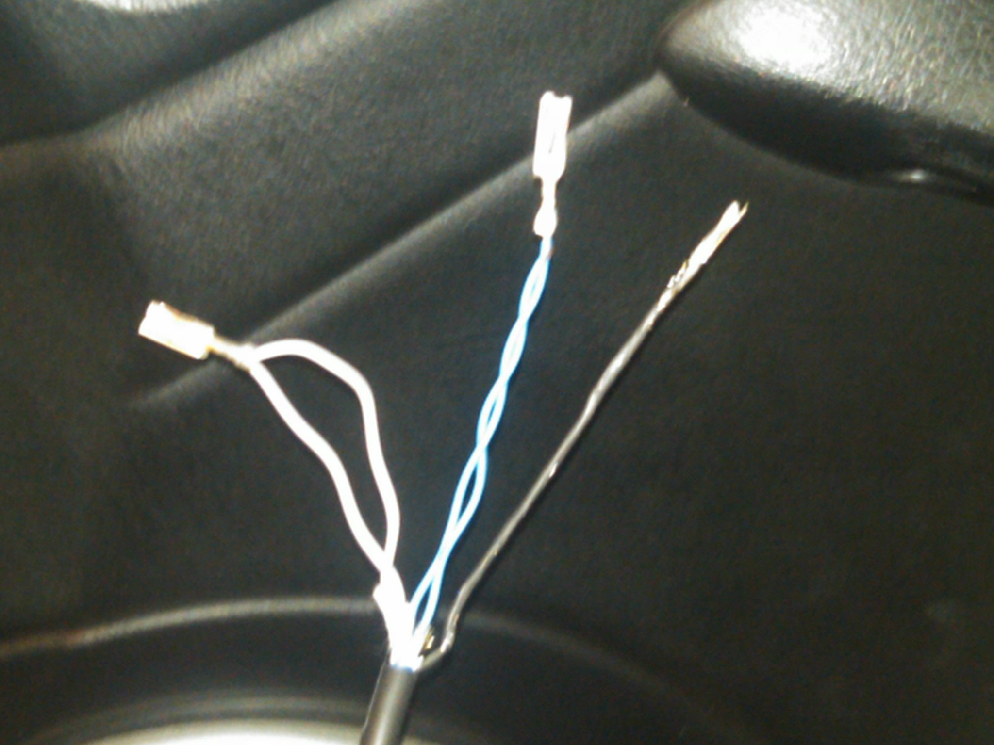
Cut apart the LS2 harness and taped it up for my setup. Used self fusing silicone tape. I may split loom it up too; it depends where it sits in the end
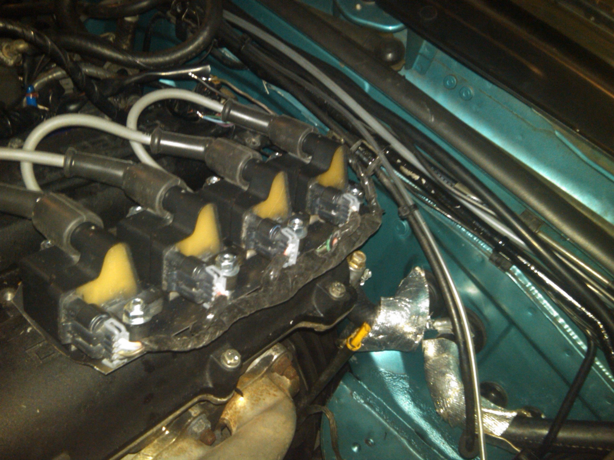
I would really really love to hide these coils or just move them so they are not just hanging out on top of my valve cover. The little shelf behind my turbine where that ground strap goes has enough space. But it is probably really damn hot...
All the wires are run and ready to be soldered/shrinkwrapped. It got really damn cold in the parking garage though so I'm done for the day.
I also got this oil cap off ebay today:
I thought it was plastic and was scratching off some shavings and the ****** cut me. Huzzah for $9 baller metal oil cap.
I had to run a few more wires to the hydra- signal ground and two signal wires for the additional coils. I used some canare star quad I have from my studio. The signal wires are twisted inside the sheath and it is foil shielded. Nice cable albeit somewhat difficult to work with.
Cut apart the LS2 harness and taped it up for my setup. Used self fusing silicone tape. I may split loom it up too; it depends where it sits in the end
I would really really love to hide these coils or just move them so they are not just hanging out on top of my valve cover. The little shelf behind my turbine where that ground strap goes has enough space. But it is probably really damn hot...
All the wires are run and ready to be soldered/shrinkwrapped. It got really damn cold in the parking garage though so I'm done for the day.
I also got this oil cap off ebay today:
I thought it was plastic and was scratching off some shavings and the ****** cut me. Huzzah for $9 baller metal oil cap.
Reply
0
0
02-06-2011, 09:24 PM
#467
Elite Member
iTrader: (12)

Join Date: Nov 2009
Location: Harpers Ferry WV
Posts: 1,516
Total Cats: 20
Hells yea coils look pretty good could you mount them on the firewall just behind the motor kinda in the same location as a NA 1.8L not sure if there is enough room but it would be a good place.
Reply
0
0
02-06-2011, 10:11 PM
#468
Elite Member
Thread Starter
iTrader: (2)
Join Date: Jan 2007
Location: Los Angeles, CA
Posts: 8,682
Total Cats: 130
No room back there- coils are too thick. :(
Maybe I can mount the plate right above the rear water neck, perpendicularly to the firewall. That might work and keep the coils from being the centerpiece of the engine bay.
Maybe I can mount the plate right above the rear water neck, perpendicularly to the firewall. That might work and keep the coils from being the centerpiece of the engine bay.
Reply
0
0
02-08-2011, 01:54 PM
#469
Fae, Make a bracket to hang the coils off the side of the IM using the bolts that attach the upper and lower halves of the IM, secure the bottom of it by using a nut/bolt through one or both of the holes in the lower IM where the IM support bracket comes off the block.
Reply
0
0
02-08-2011, 02:17 PM
#470
Elite Member
Thread Starter
iTrader: (2)
Join Date: Jan 2007
Location: Los Angeles, CA
Posts: 8,682
Total Cats: 130
I had some issues. First, when I was testing out the new coils I didn't know the plug had to be grounded before it would fire. I thought the plug wire had hot and ground. That caused me a bit of perplexification. Thinking I had fucked up and reversed hot and ground, I then switched hot and ground around. And my ECU died. That caused me sadness. Then I saw that the power for the Hydra is fused at the factory ECU location (with a FM-provided Hydra harness). And the fuse was blown. Yay! ECU not dead!
I got a new fuse and put it in, my Hydra worked AOK, I laid the plugs on the VC, and they all sparked! Now the test to see if I had done the wiring correctly. I plugged the wires into the plugs in the head, and cranked it. It fired right up! **** YEAHHHH IM ON THE ROAD AGAINN
That is a great idea. At the moment, my coolant reroute pipe is in the way and so are the fuel lines and some sensors. When I pull the IM to put the new one on I'll have to see if I can move stuff around and make that work.
Reply
0
0


 02-09-2011, 03:34 PM
#480
Elite Member
Thread Starter
iTrader: (2)
Join Date: Jan 2007
Location: Los Angeles, CA
Posts: 8,682
Total Cats: 130
I cannot wait to put the IM on the car.
Today, I measured the volume of the reamed out intake with water:
Neck: 1.5c
Upper plenum: 6c
Runners: 5.5c
Lower plenum: 3.5c
So, adding together the volume of the upper and lower plenums we get 9.5c which = 2.25L. If you add in the neck volume we get 11c which = 2.6L I think this is pretty darn good!!!- approaching 2.85L which is "ideal" assuming 1.5x displacement is a good plenum size.
I also measured the "neck" outlet in my plenum. It's 70mm in diameter. The "neck" inlet at the throttle body flange is actually 60mm.
Hmm. That's pretty close to what I was going for. I think I will try to use the stock TB and see how it does. I might try to port the TB outlet some to match. That will save the PITA of making new coldside IC tubing and getting a pipe and flange welded on and making the new TB work.
I want to put this **** on my car right naow. I just got my COPs working and went for a drive yesterday. Time to take it off the road again...
Reply
0
0


