Forced induction bottom end build... AKA the unplanned child.
 11-05-2013, 12:02 PM
#62
Elite Member
iTrader: (37)

Join Date: Apr 2010
Location: Very NorCal
Posts: 10,441
Total Cats: 1,899
For me it was more of an issue getting the old gasket remnants off the head than anything else. I couldn't see what I was doing and ended up using a mirror while working with a razorblade. I pulled the EGR, coil pack, and booster crossover to do the install. BP4W master race here so no CAS to deal with on the back of the head 

Reply
 0
0

0
11-05-2013, 12:16 PM
#63
Cpt. Slow

iTrader: (25)
Join Date: Oct 2005
Location: Oregon City, OR
Posts: 14,178
Total Cats: 1,129
No, post a picture. The temp sensor for the gauge cluster is a 1/8 npt sensor. I adapted from the 3/8 NPT on the spacer to it. I dont see where else it could go. I do know that the bolt its hitting on does go to a coolant passage but I believe the thread is metric or bspp.
This is taken from above, showing the green temp sensor used for the ECU.

This is taken from the passenger side, shooting under the CAS and at the side of the head. You can see the small cluster sensor on the side of the head. I think its on the exhaust side for 1.8s, where it gets cooked and destroyed by exhaust heat.

Once again, 1.6 FTW.
Reply
0
0
11-05-2013, 01:08 PM
#64
Elite Member
iTrader: (37)
Join Date: Apr 2010
Location: Very NorCal
Posts: 10,441
Total Cats: 1,899
And how does this apply to OP's BP4W exactly?  Ya'lls be cray postin' 1.6 data in a 1.8 thread
I like that the BEGI spacer takes coolant for the heater from right in front of the thermostat. This insures there is ALWAYS flow to keep the thermostat happy. I like this in theory, even though my M-Tuned seems to work just fine. My only other gripe about the M-Tuned was the need to extend the wiring harness for the factory temp sender, not sure if you need to do that with the BEGI or not. You may not care, I just hate cutting up factory harnesses.
Ya'lls be cray postin' 1.6 data in a 1.8 thread I like that the BEGI spacer takes coolant for the heater from right in front of the thermostat. This insures there is ALWAYS flow to keep the thermostat happy. I like this in theory, even though my M-Tuned seems to work just fine. My only other gripe about the M-Tuned was the need to extend the wiring harness for the factory temp sender, not sure if you need to do that with the BEGI or not. You may not care, I just hate cutting up factory harnesses.
Reply
0
0
 11-05-2013, 03:38 PM
#68
That wont work. The bolt head is already as thin as a thin head allen bolt, and like I said its either metric or BSPP (cant remember which), so it still needs the crush washer under the head to seal.
I'm switching to a real gauge in the cluster since my stock one doesn't work anyways And I'll just get a low pro sender that will clear. Or a plug and drill some other spot for the sender.
I'm switching to a real gauge in the cluster since my stock one doesn't work anyways And I'll just get a low pro sender that will clear. Or a plug and drill some other spot for the sender.
Reply
0
0
11-05-2013, 04:17 PM
#69
Elite Member
iTrader: (8)

Join Date: Dec 2008
Location: Kingston, Ontario
Posts: 2,910
Total Cats: 51
That wont work. The bolt head is already as thin as a thin head allen bolt, and like I said its either metric or BSPP (cant remember which), so it still needs the crush washer under the head to seal.
I'm switching to a real gauge in the cluster since my stock one doesn't work anyways And I'll just get a low pro sender that will clear. Or a plug and drill some other spot for the sender.
I'm switching to a real gauge in the cluster since my stock one doesn't work anyways And I'll just get a low pro sender that will clear. Or a plug and drill some other spot for the sender.
Reply
0
0

 11-16-2013, 10:01 PM
#73
Senior Member
Thread Starter
iTrader: (2)

Join Date: Oct 2013
Location: Goleta, Southern California
Posts: 520
Total Cats: 27
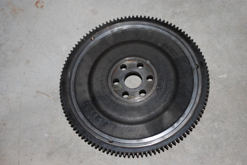
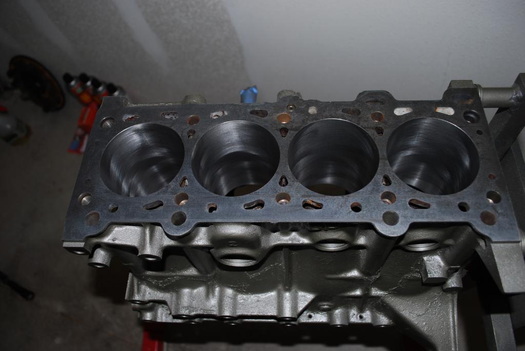
Got the block, crank and flywheel back.
I told the machinist to take what he felt was safe off the flywheel. I weighed it at 15.3 lbs. on a mail scale at work. Not bad for $45.
I cleaned and painted the block today. I told the GF she could pick the color and was worried that the parts store would have pink. Luckily they did not and she picked a color that I can live with. I would have gone with black, but I like the change and glad we went gray.
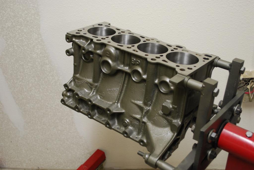
New bores waiting for slugs.
I told the machinist to take what he felt was safe off the flywheel. I weighed it at 15.3 lbs. on a mail scale at work. Not bad for $45.

I cleaned and painted the block today. I told the GF she could pick the color and was worried that the parts store would have pink. Luckily they did not and she picked a color that I can live with. I would have gone with black, but I like the change and glad we went gray.

New bores waiting for slugs.

Reply
0
0
 11-21-2013, 12:24 AM
#75
Senior Member
Thread Starter
iTrader: (2)
Join Date: Oct 2013
Location: Goleta, Southern California
Posts: 520
Total Cats: 27
I was able to borrow a bore gauge from a guy at work, thanks Dave!
I told the machine shop to aim for .003"-.0035" piston to wall clearance. Looks like he got .0038"-.0041". I'm thinking they might be closer together if the block was on a table instead of the engine stand. Seems like the bore opens up by .0001" each cylinder I go out from the engine stand. Anyone know if the stand may have a hand in the readings?
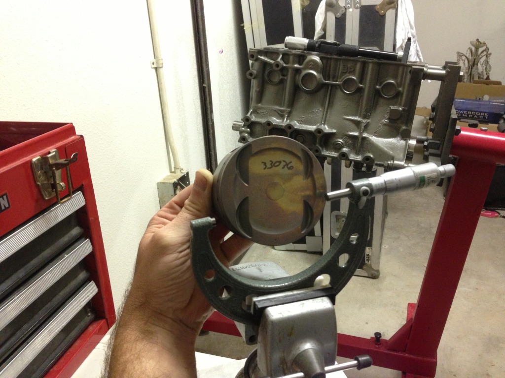
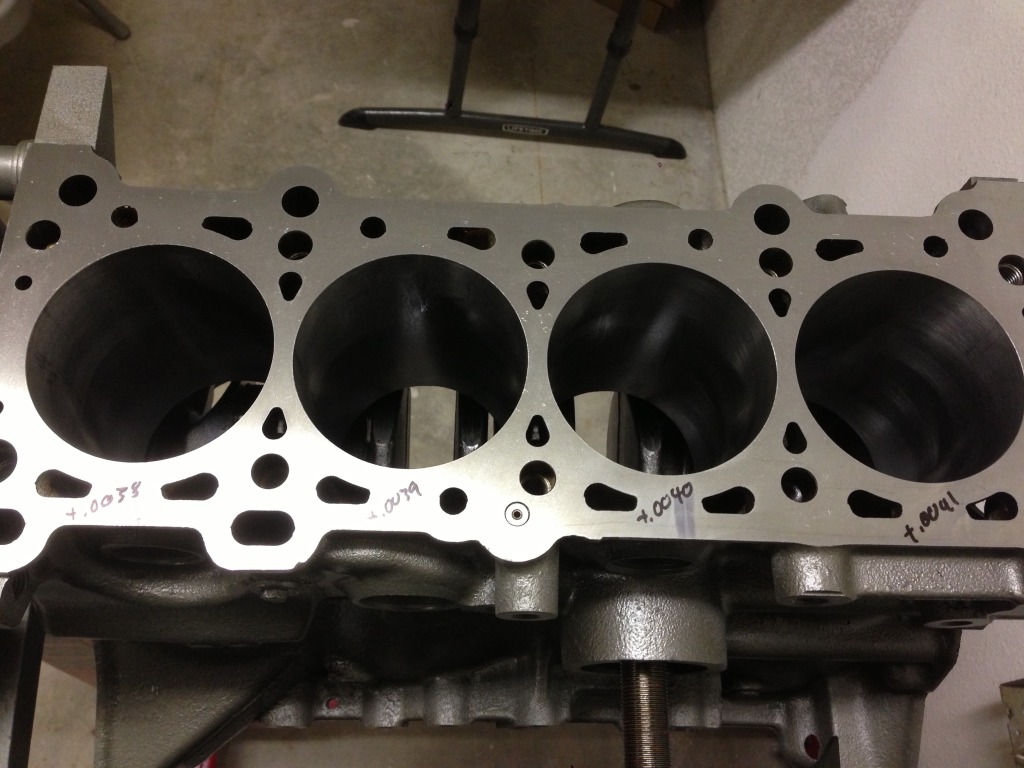
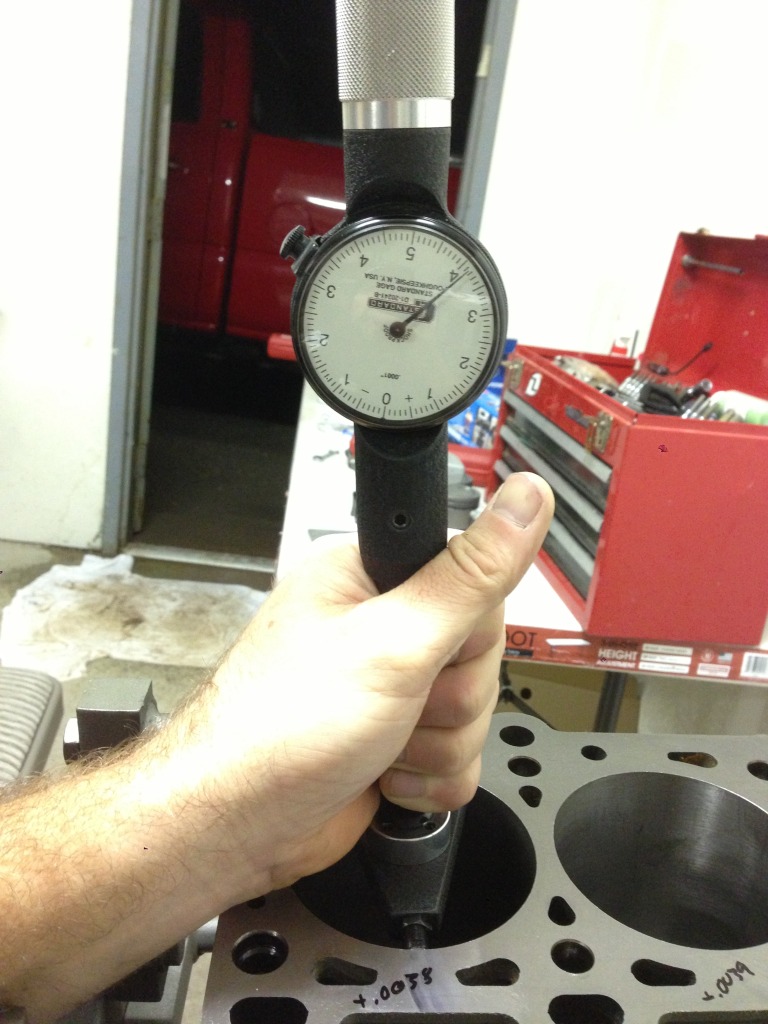
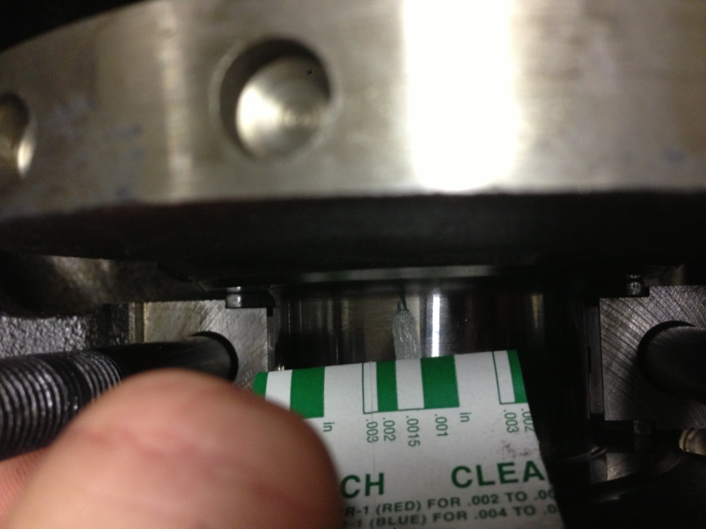
All main bearing clearances were .0015"- slightly over .001".
I told the machine shop to aim for .003"-.0035" piston to wall clearance. Looks like he got .0038"-.0041". I'm thinking they might be closer together if the block was on a table instead of the engine stand. Seems like the bore opens up by .0001" each cylinder I go out from the engine stand. Anyone know if the stand may have a hand in the readings?
All main bearing clearances were .0015"- slightly over .001".
Reply
0
0
11-25-2013, 08:55 PM
#76
Senior Member
Thread Starter
iTrader: (2)
Join Date: Oct 2013
Location: Goleta, Southern California
Posts: 520
Total Cats: 27
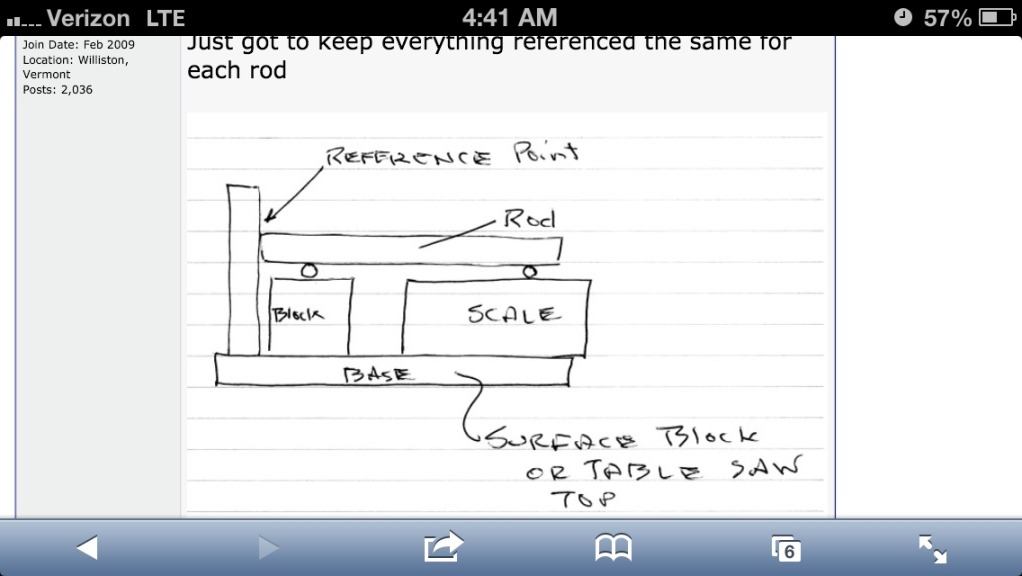
I tried to weigh my rods end for end on Friday night. I thought it would be easy to build a little fixture but it turns out, not so much. I couldn't get the same weight twice. Plus the scale I was using was probably not that accurate and didn't measure down to tenths of a gram. I order a scale from amazon that should do the trick. Now I just need a fixture. I would love to buy one from summit or jets but can't justify spending $180 when I know I wouldn't use it again for quite some time. I found this on another forum. I'm going to give it a try. Anyone have any other bright ideas?
Reply
0
0
11-27-2013, 08:38 PM
#77
Senior Member
Thread Starter
iTrader: (2)
Join Date: Oct 2013
Location: Goleta, Southern California
Posts: 520
Total Cats: 27
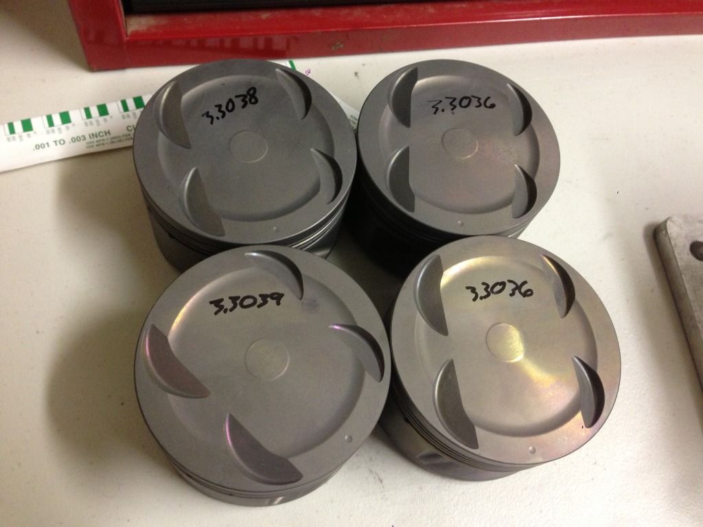
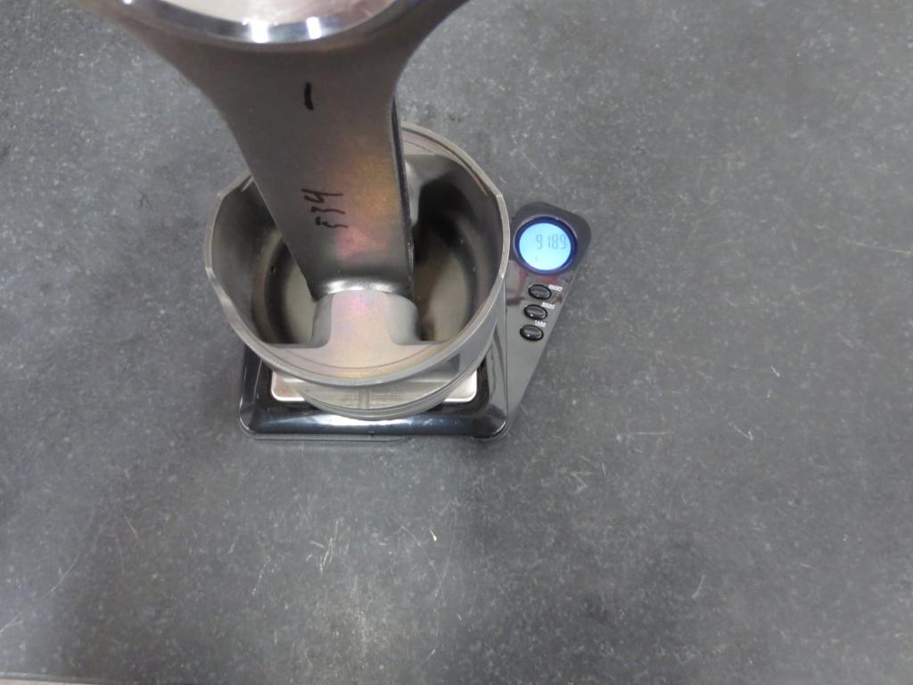
Alright, screw it. I played the switch piston pins around game and then matched the heaviest rod with the lightest piston. I bought a $10 scale from amazon that works great down to .1 grams. I got all four within .5 grams of each other, no bearings or rings. Close enough for me.
#1
#2
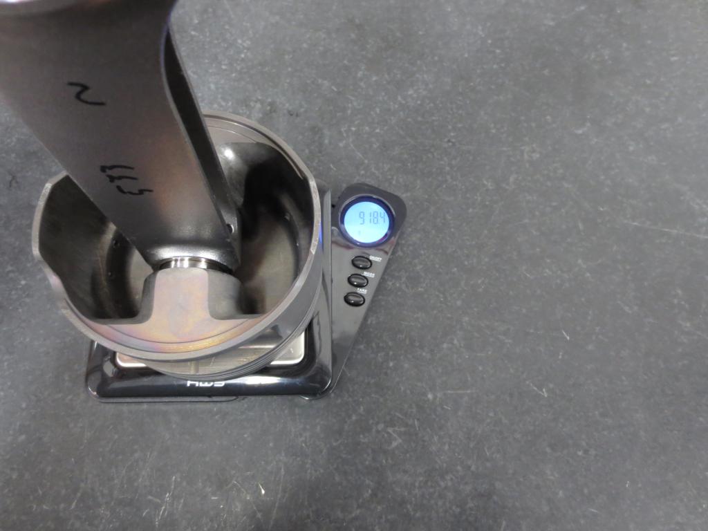
#3
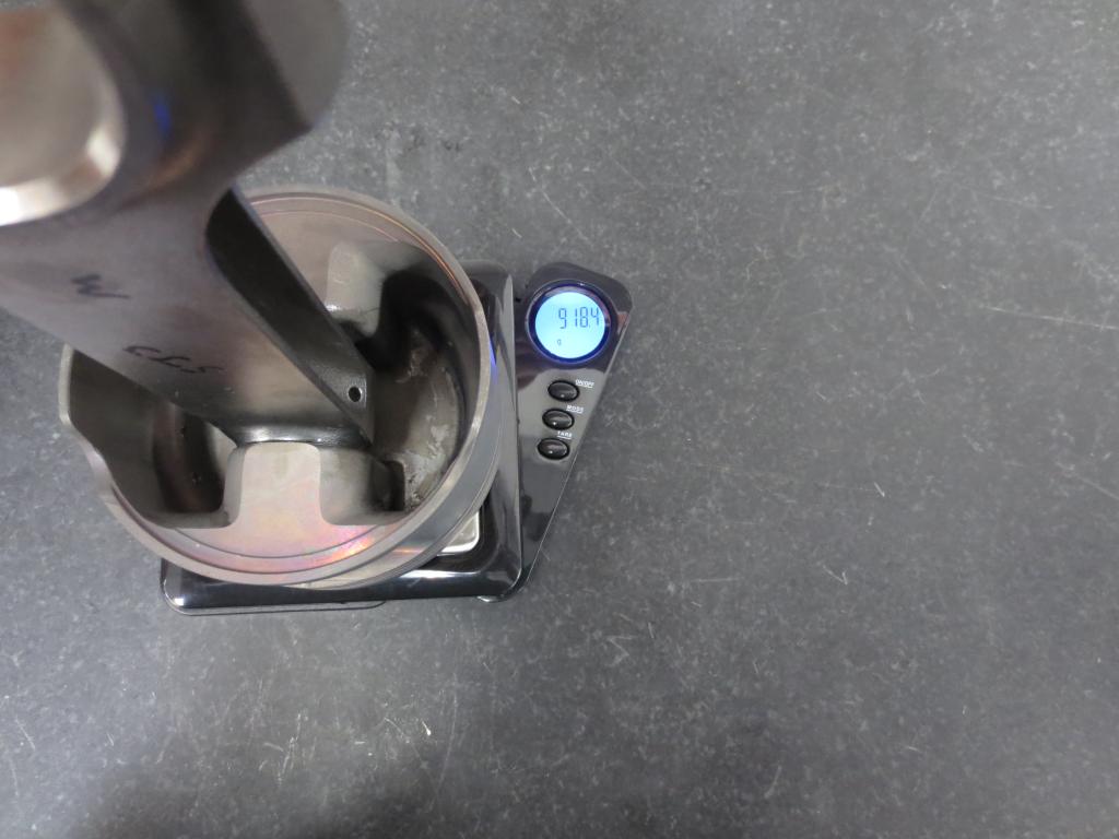
#4
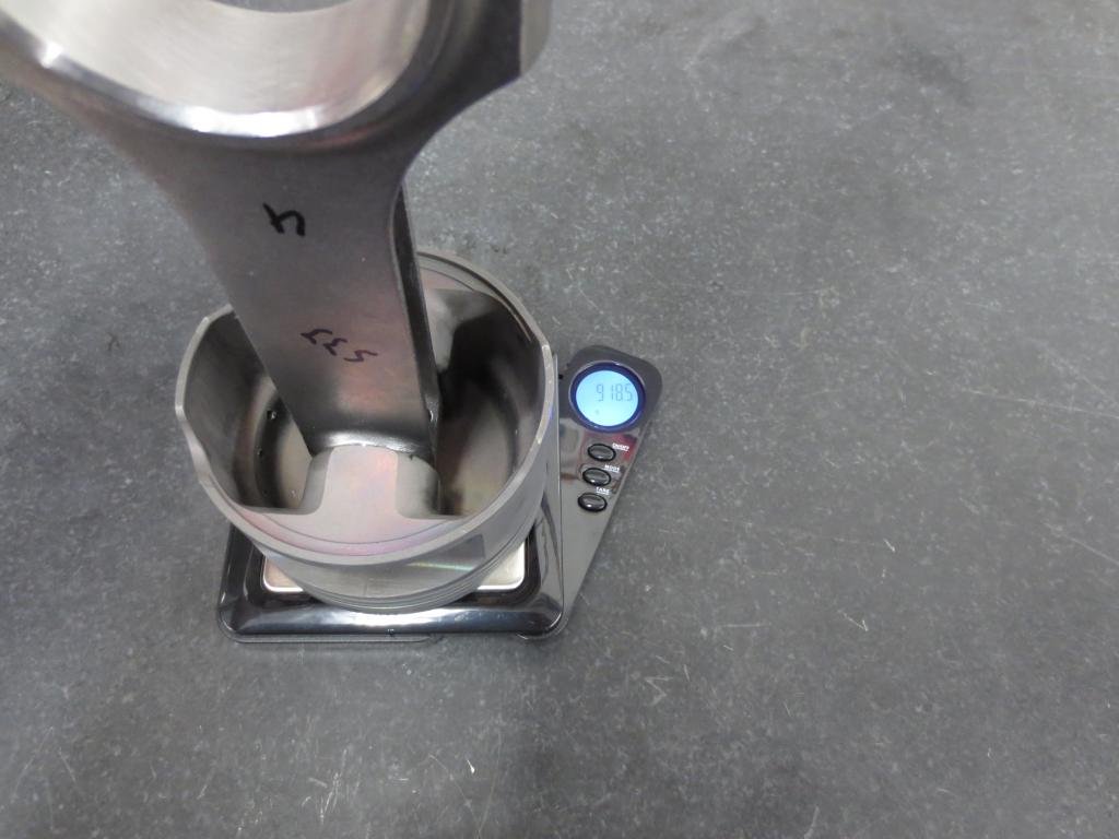
I know that it could have gone together using any piston, with any pin and any rod and run just fine. However I think my $10 investment was the way to go. Cheapest balance ever?
#1

#2

#3

#4

I know that it could have gone together using any piston, with any pin and any rod and run just fine. However I think my $10 investment was the way to go. Cheapest balance ever?
Reply
0
0
11-30-2013, 12:11 AM
#78
Senior Member
Thread Starter
iTrader: (2)
Join Date: Oct 2013
Location: Goleta, Southern California
Posts: 520
Total Cats: 27
Gapping rings. All top rings were .012"-.013" out of the box. According to the Wseco spec sheet for turbo/nitrous top gap should be .005 per inch of bore equaling about .0165" total for my~ 3.308". I gapped them to .017-.018".
The second rings out of the box were .019-.020". A little over the specked .0055" per inch of bore or ~.018 called for. Probably safe for anything but "circle track or race". The important part I believe is that the second ring has a larger gap than the top.
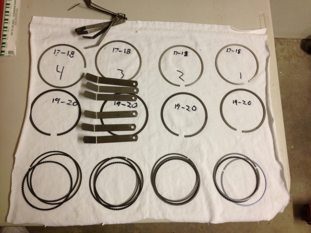
The second rings out of the box were .019-.020". A little over the specked .0055" per inch of bore or ~.018 called for. Probably safe for anything but "circle track or race". The important part I believe is that the second ring has a larger gap than the top.
Reply
0
0
11-30-2013, 11:35 PM
#79
Senior Member
Thread Starter
iTrader: (2)
Join Date: Oct 2013
Location: Goleta, Southern California
Posts: 520
Total Cats: 27
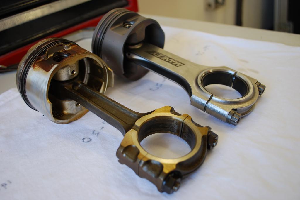
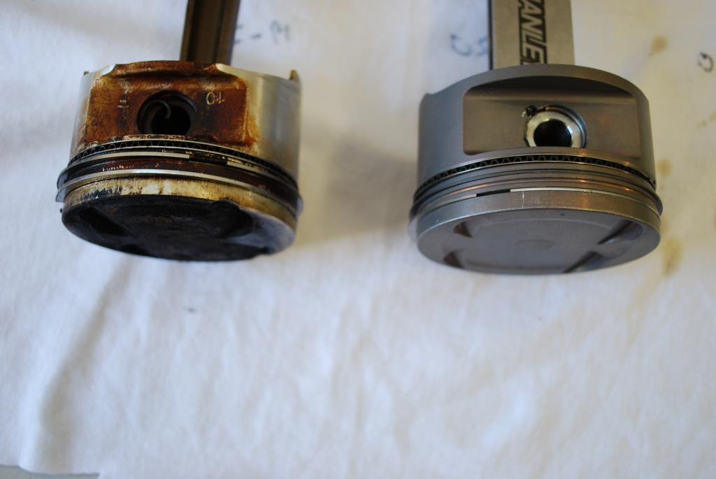
Fooling around comparing stock vs Supertech and Manley.
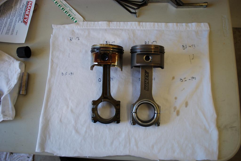
Old pistons, rods and rings (no bearings were):
1) 945.1 grams
2) 945.1
3) 952.8
4) 944.7
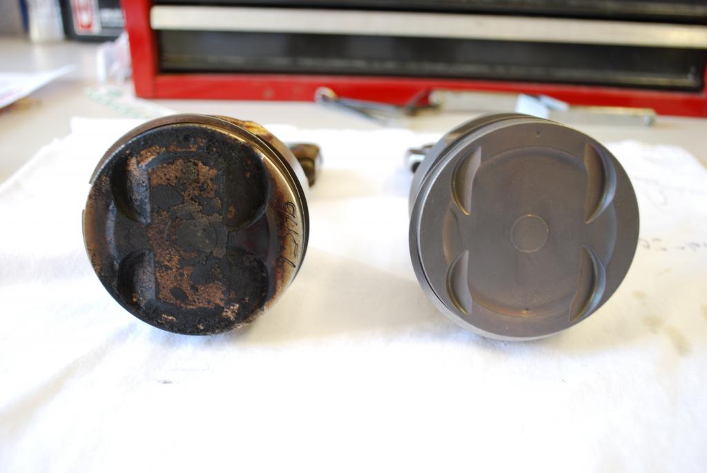
All these weights were taken as they were removed form the engine (dirty). I removed a bit of carbon from #3 just to see if that was causing the large difference. It weight before I scraped was 953.1 grams. Seems a little far off compared to the rest.
I weighed the new setup just as the old with no bearings just to see a closer apples to apples comparison. Obviously the new assemblies do not have carbon build up on them but I thought with the beefier rods and larger 84mm pistons they would weigh more than the old.
1) 938.7
2) 938.5
3) 938.4
4) 938.6
New pistons, rods, rings and bearings (ready to be assembled).
1) 971.0
2) 970.7
3) 970.6
4) 970.8


Old pistons, rods and rings (no bearings were):
1) 945.1 grams
2) 945.1
3) 952.8
4) 944.7
All these weights were taken as they were removed form the engine (dirty). I removed a bit of carbon from #3 just to see if that was causing the large difference. It weight before I scraped was 953.1 grams. Seems a little far off compared to the rest.
I weighed the new setup just as the old with no bearings just to see a closer apples to apples comparison. Obviously the new assemblies do not have carbon build up on them but I thought with the beefier rods and larger 84mm pistons they would weigh more than the old.
1) 938.7
2) 938.5
3) 938.4
4) 938.6
New pistons, rods, rings and bearings (ready to be assembled).
1) 971.0
2) 970.7
3) 970.6
4) 970.8
Reply
0
0


