Ian's 99 build thread
 11-22-2014, 12:23 PM
#61
Elite Member
iTrader: (37)

Join Date: Apr 2010
Location: Very NorCal
Posts: 10,441
Total Cats: 1,899
I really need to sign up with MazdaComp and get access the sweet sweet parts catalog.
Good progress, I'm loving every minute of it. In theory I know how to do all this stuff but its great that you are documenting the process.
Good progress, I'm loving every minute of it. In theory I know how to do all this stuff but its great that you are documenting the process.

Reply
 0
0

0
11-22-2014, 01:19 PM
#62
Elite Member

Thread Starter
Join Date: Mar 2007
Location: Santa Clara, CA
Posts: 5,165
Total Cats: 855
--Ian
Reply
0
0
11-23-2014, 12:59 AM
#63
Elite Member
Thread Starter
Join Date: Mar 2007
Location: Santa Clara, CA
Posts: 5,165
Total Cats: 855
Since my BE pump isn't here yet, there wasn't a whole lot I could do to it today. I did move some shims around on the head and remeasure stuff -- I must've had two feeler gauges stuck together when I checked them earlier in the week, because now it's all right where I expected it to be. So the intake cam is all shimmed properly (no new pictures -- it doesn't really look all that different from before), and I took everything out, washed it all down with brake cleaner, lubed it up with assembly lube, and reinstalled. Head should be good to go at this point.
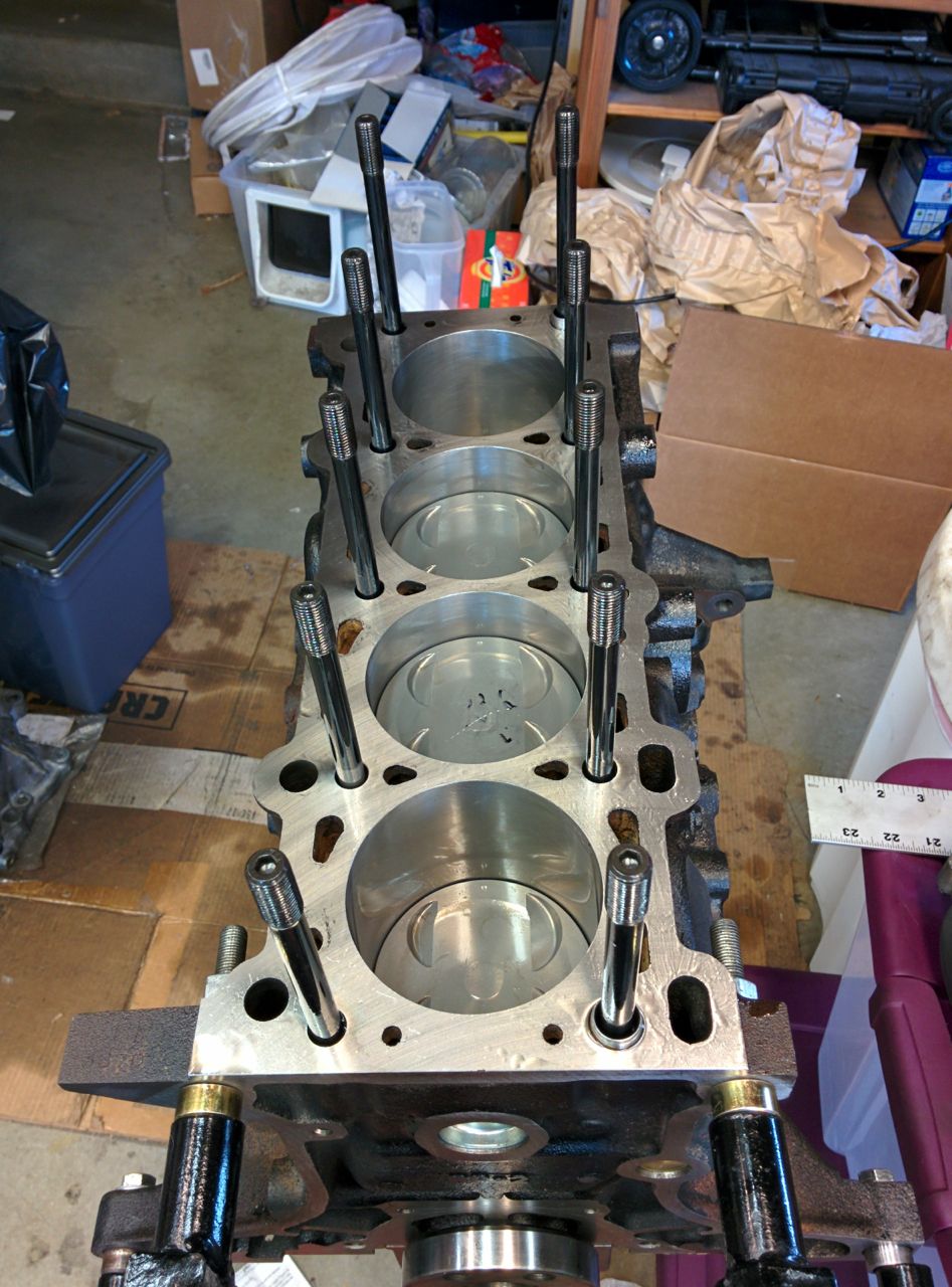
I thought about putting the head on the block, but decided that was tempting Murphy too much, since I don't have the oil pump/pan/etc installed yet. So instead I just put in the dowels and head studs.
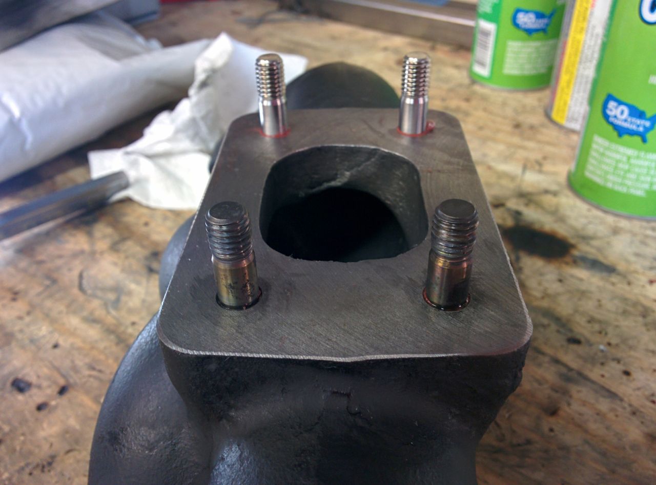
When I took the motor apart, the FM manifold had warped, closing up the slots in the flange and grabbing onto the exhaust studs, it was also leaking near #4. It's old enough to be out of warranty, but FM offered me a discount on a new one if I wanted it, and I took them up on it. This meant I needed to take the inconel studs out of the old manifold and put them in the new one. Alas, a couple of them really didn't want to come out of the old manifold, and the threads got a bit mangled.
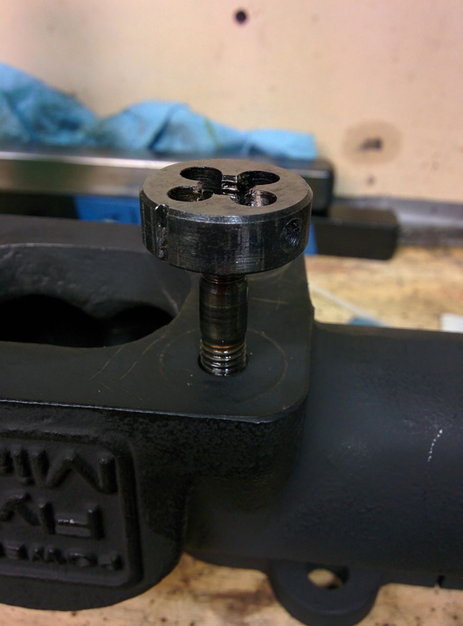
Since they're like $25 each, I decided to see if I could clean up the threads to usability with a die from my super-ultra-cheap Harbor Freight metric-tap-and-tie set. Hah. The set screw in the pot metal die holder stripped out, and I wound up turning the die with a pair of vise-grips instead. It cleaned up one of them enough that it would now thread into the manifold, but wouldn't go onto the other one, I'm guessing I just trashed the cutting heads doing the first one. Ah well, I didn't expect much.
Hard to see in the photo, but the threads are messed up about halfway down:
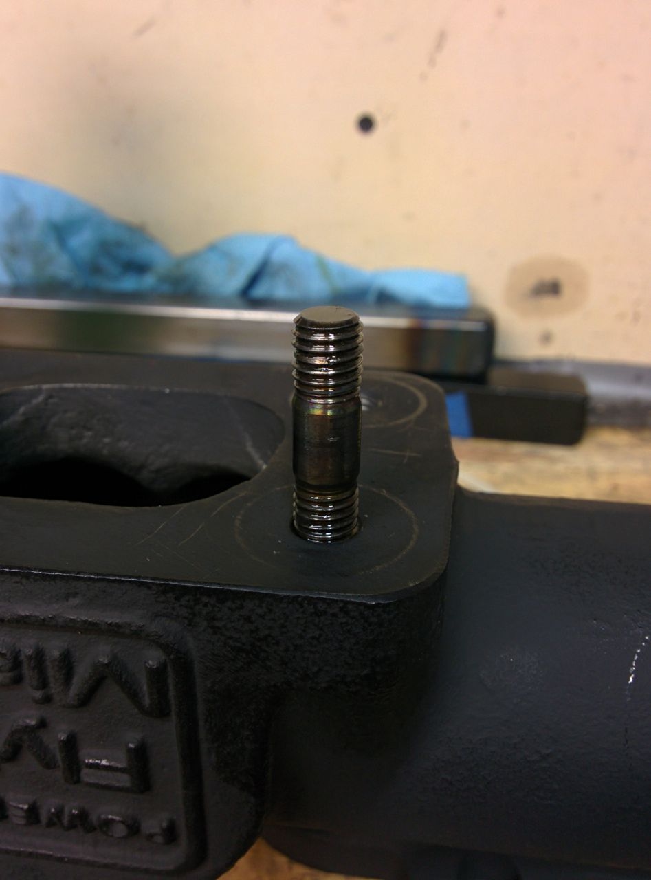
Stupid cheap tool steel.
So I guess I'll have to order at least one new inconel stud.
(and no, I wasn't actually tapping the studs while mounted in the manifold, I just stuck it in there to take a photo of it.)
--Ian
I thought about putting the head on the block, but decided that was tempting Murphy too much, since I don't have the oil pump/pan/etc installed yet. So instead I just put in the dowels and head studs.
When I took the motor apart, the FM manifold had warped, closing up the slots in the flange and grabbing onto the exhaust studs, it was also leaking near #4. It's old enough to be out of warranty, but FM offered me a discount on a new one if I wanted it, and I took them up on it. This meant I needed to take the inconel studs out of the old manifold and put them in the new one. Alas, a couple of them really didn't want to come out of the old manifold, and the threads got a bit mangled.
Since they're like $25 each, I decided to see if I could clean up the threads to usability with a die from my super-ultra-cheap Harbor Freight metric-tap-and-tie set. Hah. The set screw in the pot metal die holder stripped out, and I wound up turning the die with a pair of vise-grips instead. It cleaned up one of them enough that it would now thread into the manifold, but wouldn't go onto the other one, I'm guessing I just trashed the cutting heads doing the first one. Ah well, I didn't expect much.
Hard to see in the photo, but the threads are messed up about halfway down:
Stupid cheap tool steel.
So I guess I'll have to order at least one new inconel stud.
(and no, I wasn't actually tapping the studs while mounted in the manifold, I just stuck it in there to take a photo of it.
)--Ian
Reply
0
0
11-23-2014, 01:59 AM
#64
Elite Member
Thread Starter
Join Date: Mar 2007
Location: Santa Clara, CA
Posts: 5,165
Total Cats: 855
Did a few other random things for it today. The standard intake for the FM2 system is a custom silicone elbow with a 2.5" diameter on one end (the long end) and 2.75" diameter on the other. The 2.75" end goes to either the stock MAF or a MAF delete pipe, which then goes to an oval K&N filter. Like this:
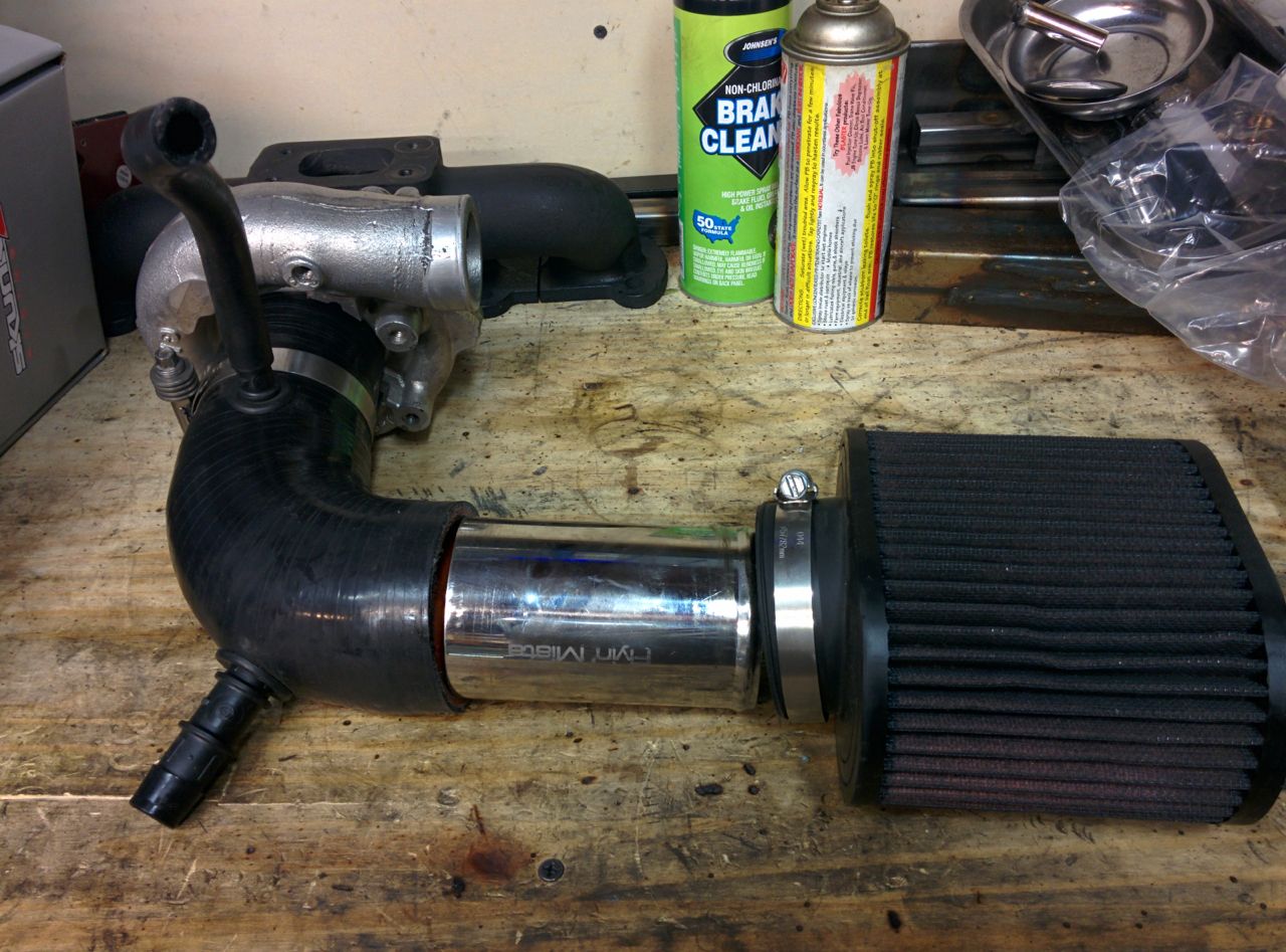
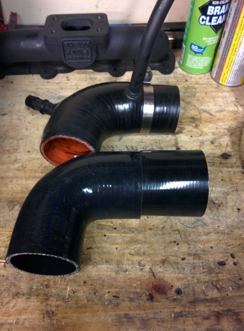
FM has 3.5" and 4" intakes available for the FM2R kit using 2860s, 3071s, etc, but none for the 3.0" intake flange on the 2863, so I ordered a few parts from silicone intakes.com:
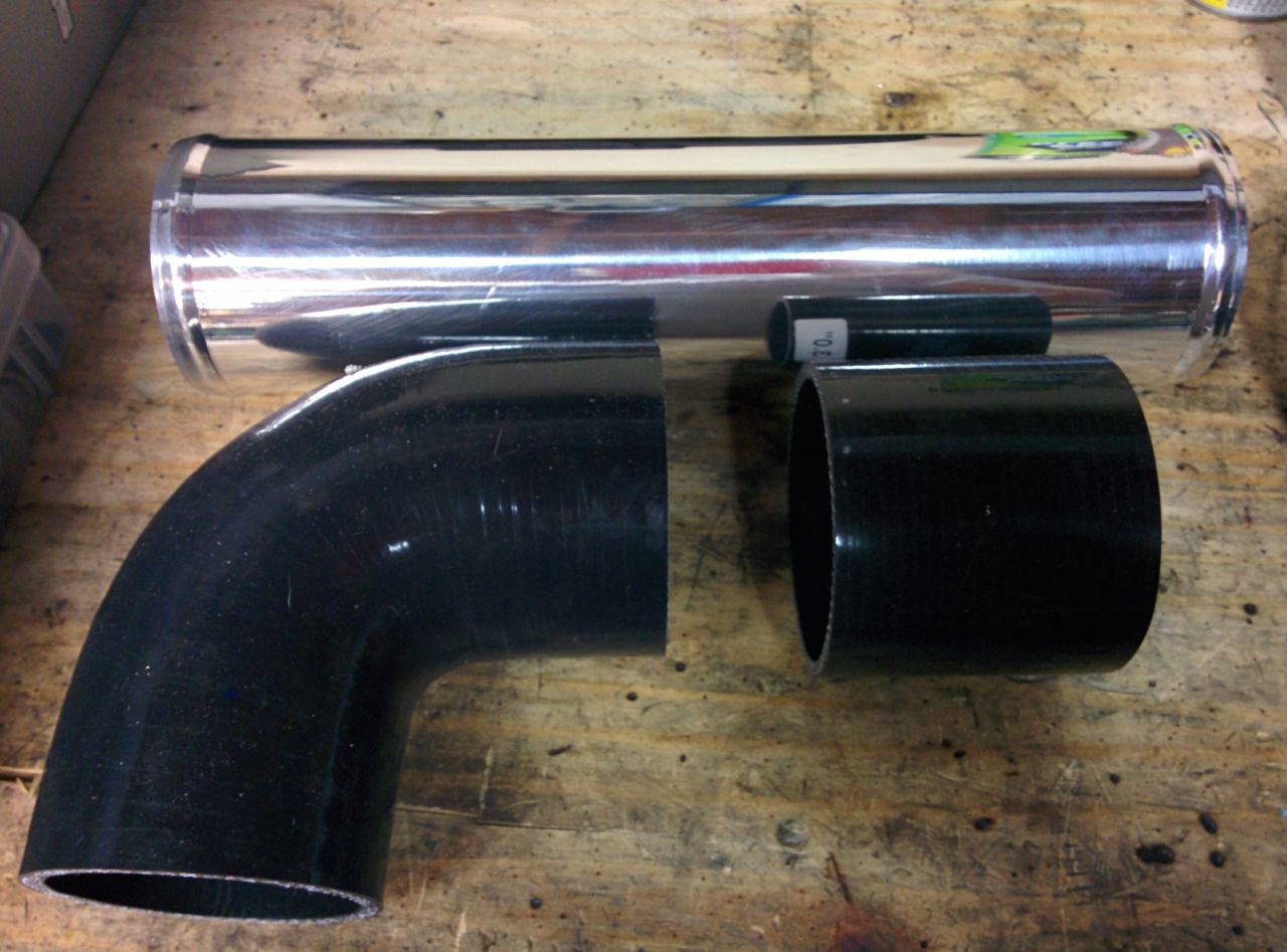
I decided I wanted to keep the FM2 intake box, but there's no 3.0" inlet K&N filter that fits in it. It seemed the simplest thing to do was to just remake the FM intake, but swap out the elbow for one that fit the 2863. So, an elbow that goes from 3.0" to 2.75", and (since the available elbows have two short ends), a short 3.0" straight coupler to extend it, plus some aluminum pipe to join the two silicone bits. The coupler needs trimming, I'll do that once the engine and turbo are in the car and I can test-fit for length. It's probably not ideal to have intake pipes that start out at 2.75" and then flare out to 3.0" right before the turbo, but I'm not sure it's a big-enough deal to really worry about, and it will be convenient not to have to remake the filter mount/etc.
Moving stuff around the garage, I noticed something interesting in the pile of junk parts that came out of the donor motor. When I tore it down, the bottom end from the block all *looked* OK, but on further analysis it's got at least two bent rods. This motor was out of a 10AE that had a Link Piggyback FM2 turbo kit installed, one which apparently wasn't run with as much care and octane as the one I used to have on my stock motor. There wasn't any sign of detonation on the pistons, but the rods bear a certain resemblance to a piece of yellow fruit...
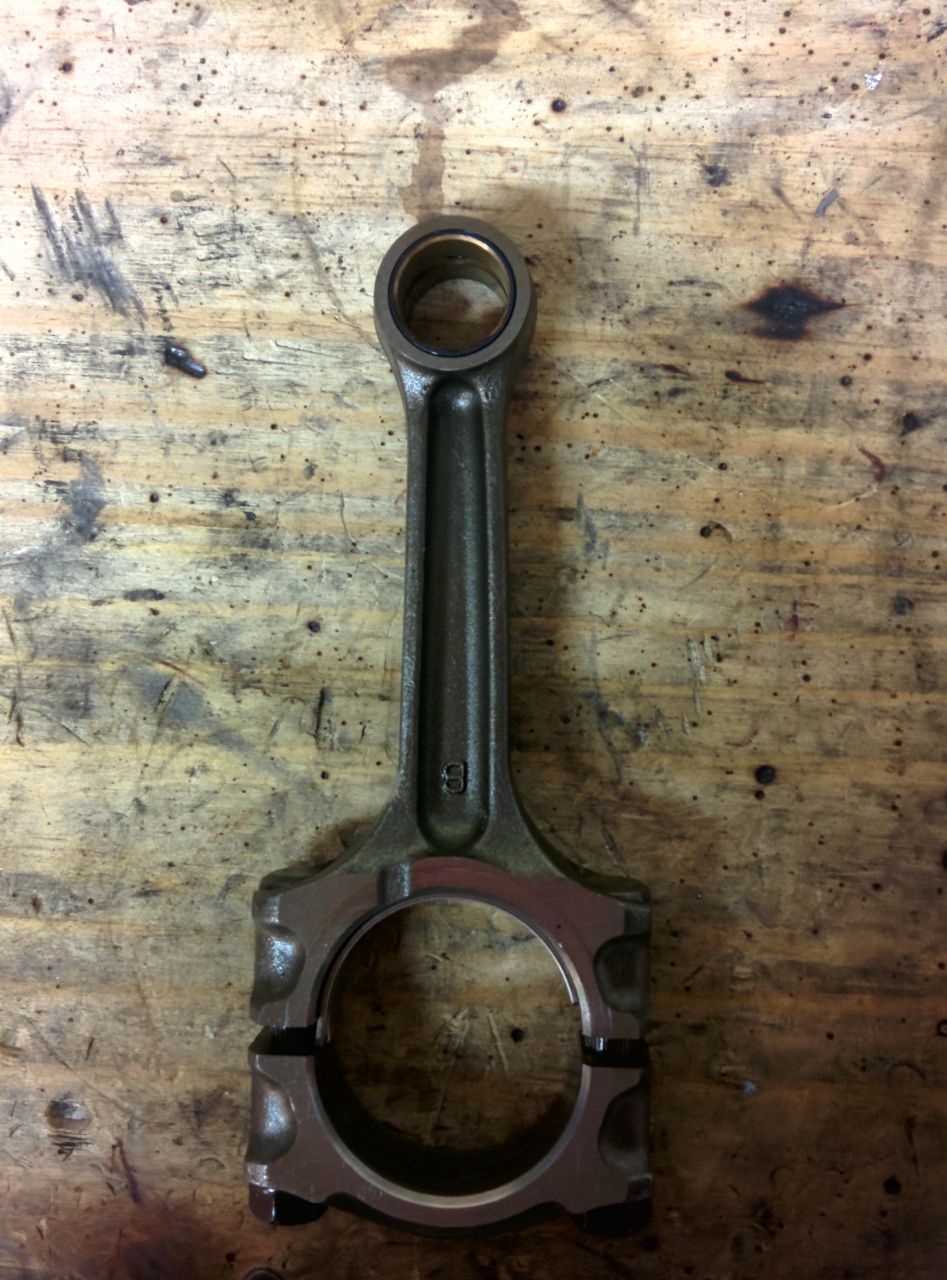
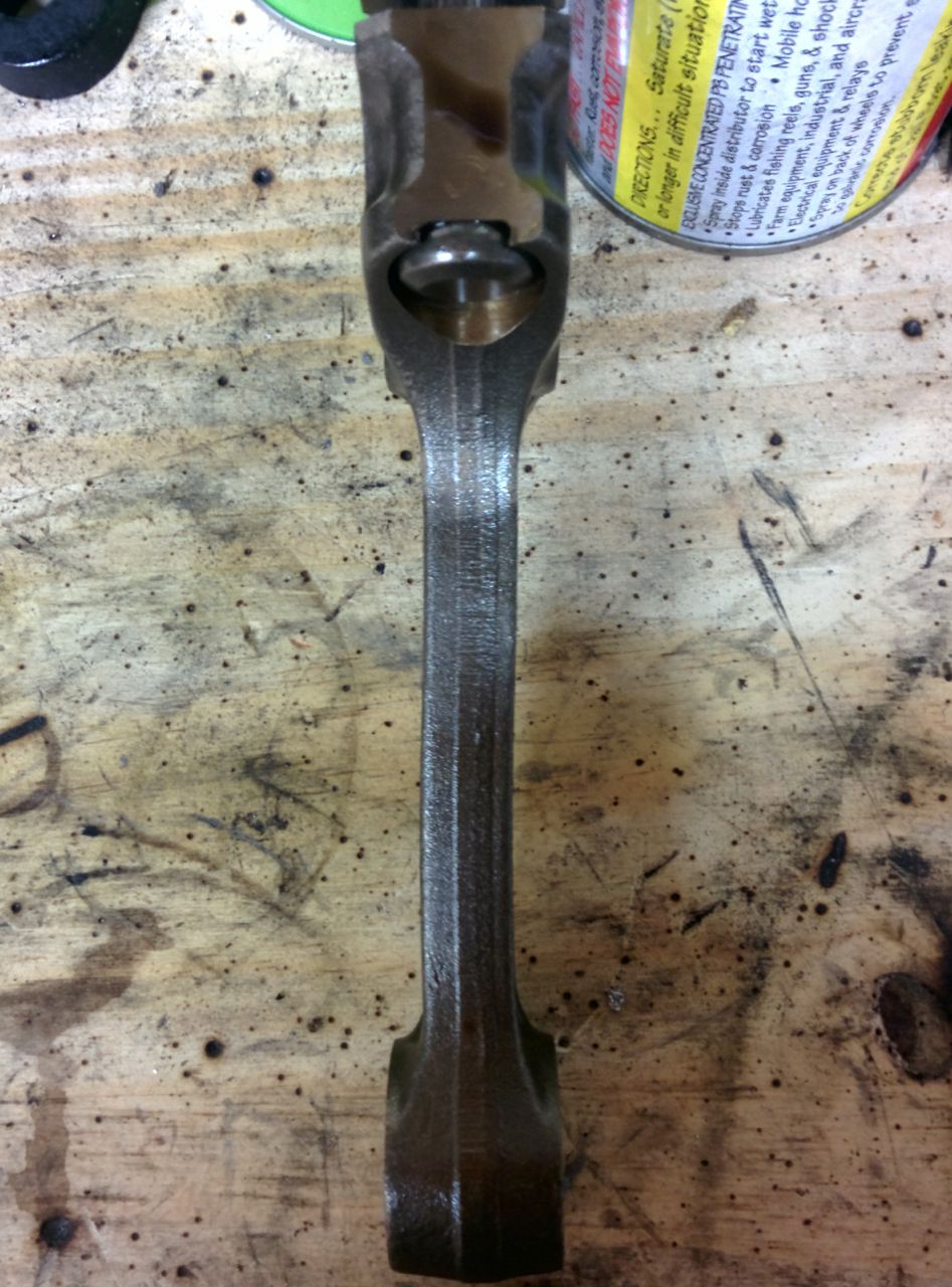
So I guess I don't feel too bad about tearing apart a bottom end that had good-looking bearings after all.
--Ian
FM has 3.5" and 4" intakes available for the FM2R kit using 2860s, 3071s, etc, but none for the 3.0" intake flange on the 2863, so I ordered a few parts from silicone intakes.com:
I decided I wanted to keep the FM2 intake box, but there's no 3.0" inlet K&N filter that fits in it. It seemed the simplest thing to do was to just remake the FM intake, but swap out the elbow for one that fit the 2863. So, an elbow that goes from 3.0" to 2.75", and (since the available elbows have two short ends), a short 3.0" straight coupler to extend it, plus some aluminum pipe to join the two silicone bits. The coupler needs trimming, I'll do that once the engine and turbo are in the car and I can test-fit for length. It's probably not ideal to have intake pipes that start out at 2.75" and then flare out to 3.0" right before the turbo, but I'm not sure it's a big-enough deal to really worry about, and it will be convenient not to have to remake the filter mount/etc.
Moving stuff around the garage, I noticed something interesting in the pile of junk parts that came out of the donor motor. When I tore it down, the bottom end from the block all *looked* OK, but on further analysis it's got at least two bent rods. This motor was out of a 10AE that had a Link Piggyback FM2 turbo kit installed, one which apparently wasn't run with as much care and octane as the one I used to have on my stock motor. There wasn't any sign of detonation on the pistons, but the rods bear a certain resemblance to a piece of yellow fruit...
So I guess I don't feel too bad about tearing apart a bottom end that had good-looking bearings after all.
--Ian
Reply
0
0
12-07-2014, 01:13 PM
#65
Elite Member
Thread Starter
Join Date: Mar 2007
Location: Santa Clara, CA
Posts: 5,165
Total Cats: 855
My build was stalled for a few weeks from a combination of the holidays and the broken oil pump housing. I ordered a boundary pump, but it took a while to get here, finally showing up a few days ago.
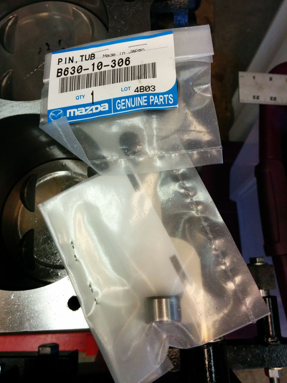
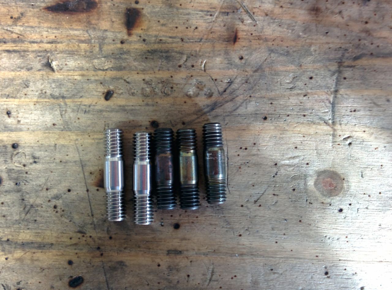
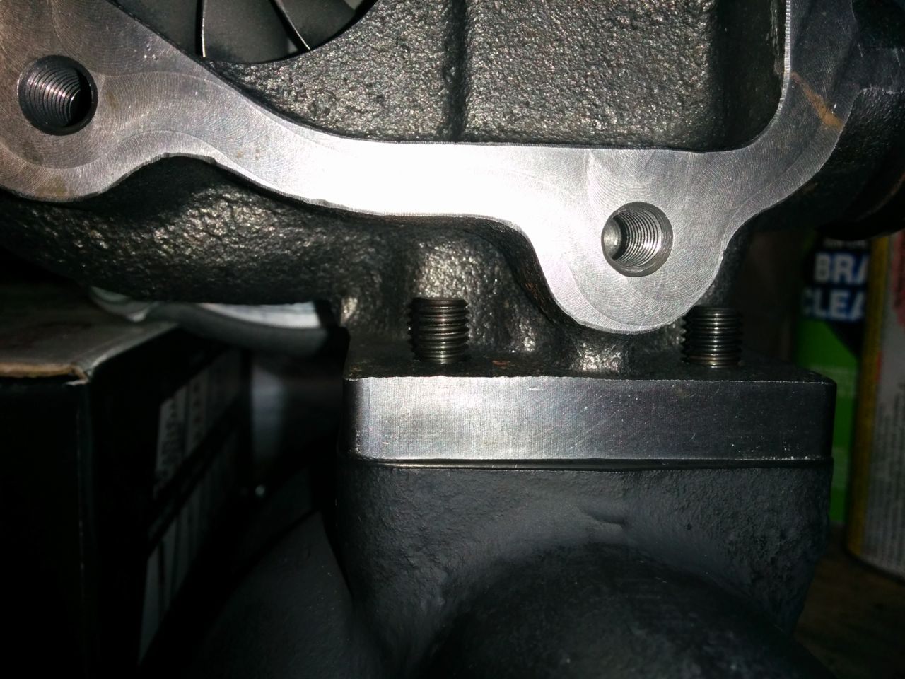
So yesterday I went to put it in, only to discover that the oil pump O-ring that was supposed to be in my Mazda rebuild kit was missing! So I went through some of the other new parts that had shown up, like the two replacement inconel studs from FM. They're slightly longer than the original ones I had. No big deal, I put the ones with the extra length on the CHRA side of the mounting, there's a bit more clearance for the nuts there.
--Ian
Reply
0
0
12-07-2014, 01:36 PM
#66
Elite Member
Thread Starter
Join Date: Mar 2007
Location: Santa Clara, CA
Posts: 5,165
Total Cats: 855
Argh, dammit, this is about the fifth time I've typed this post, some key combination I'm hitting keeps sending the browser back to the previous page and losing all my typing.
So later in the afternoon, I located an oil pump O-ring (huge thanks to Savington!). With that, the assembly could continue. All that and I didn't get a picture of it, but it's not all that interesting to look at.
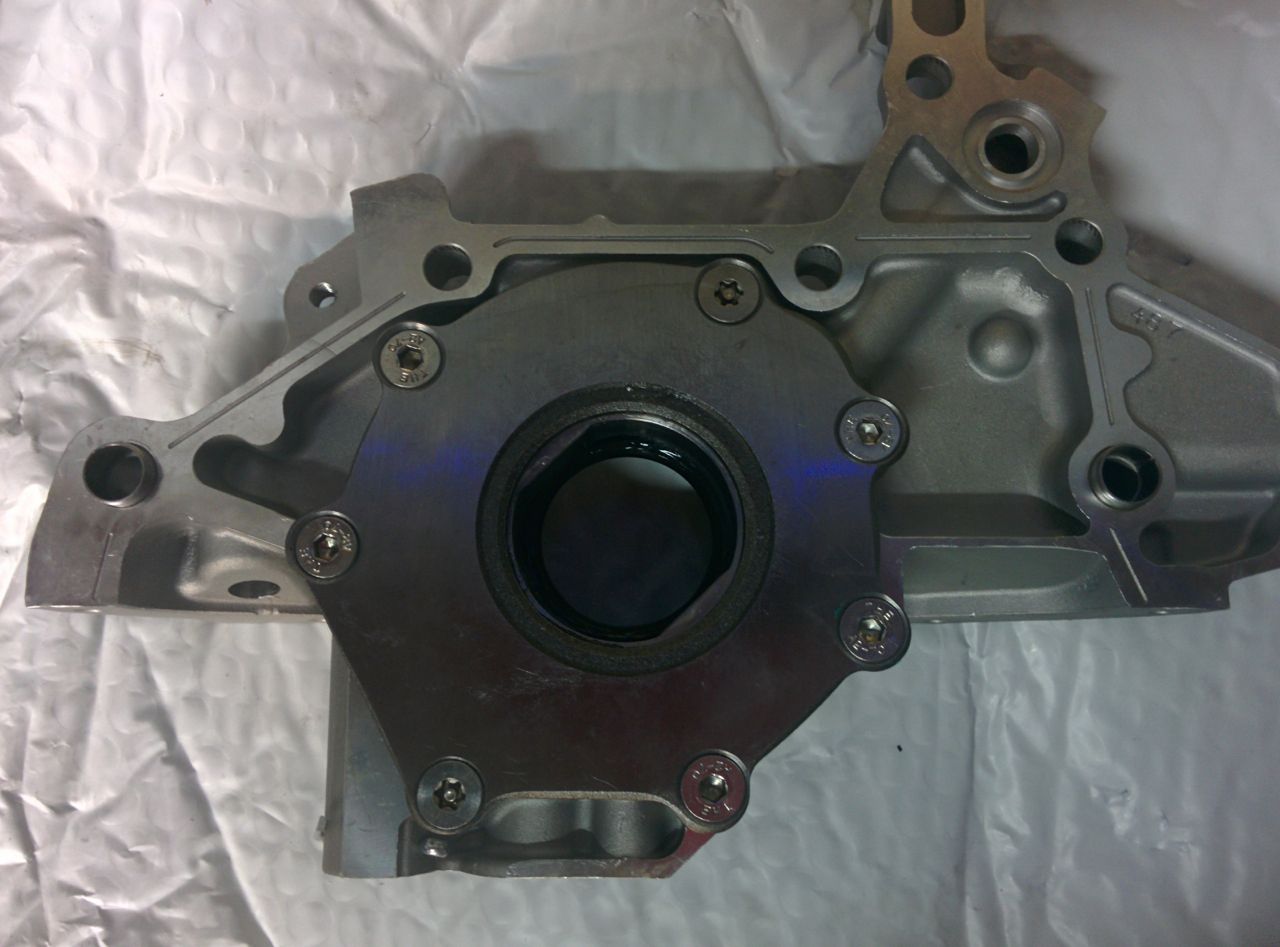
So first the oil pump goes on the block:
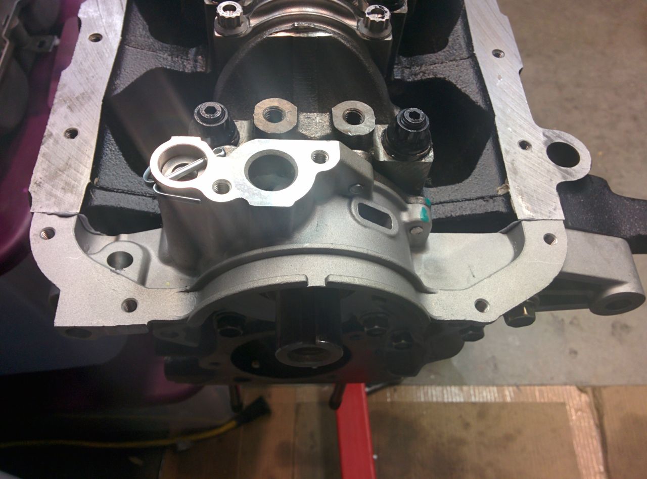
And then I squirted gray RTV on a bunch of things:
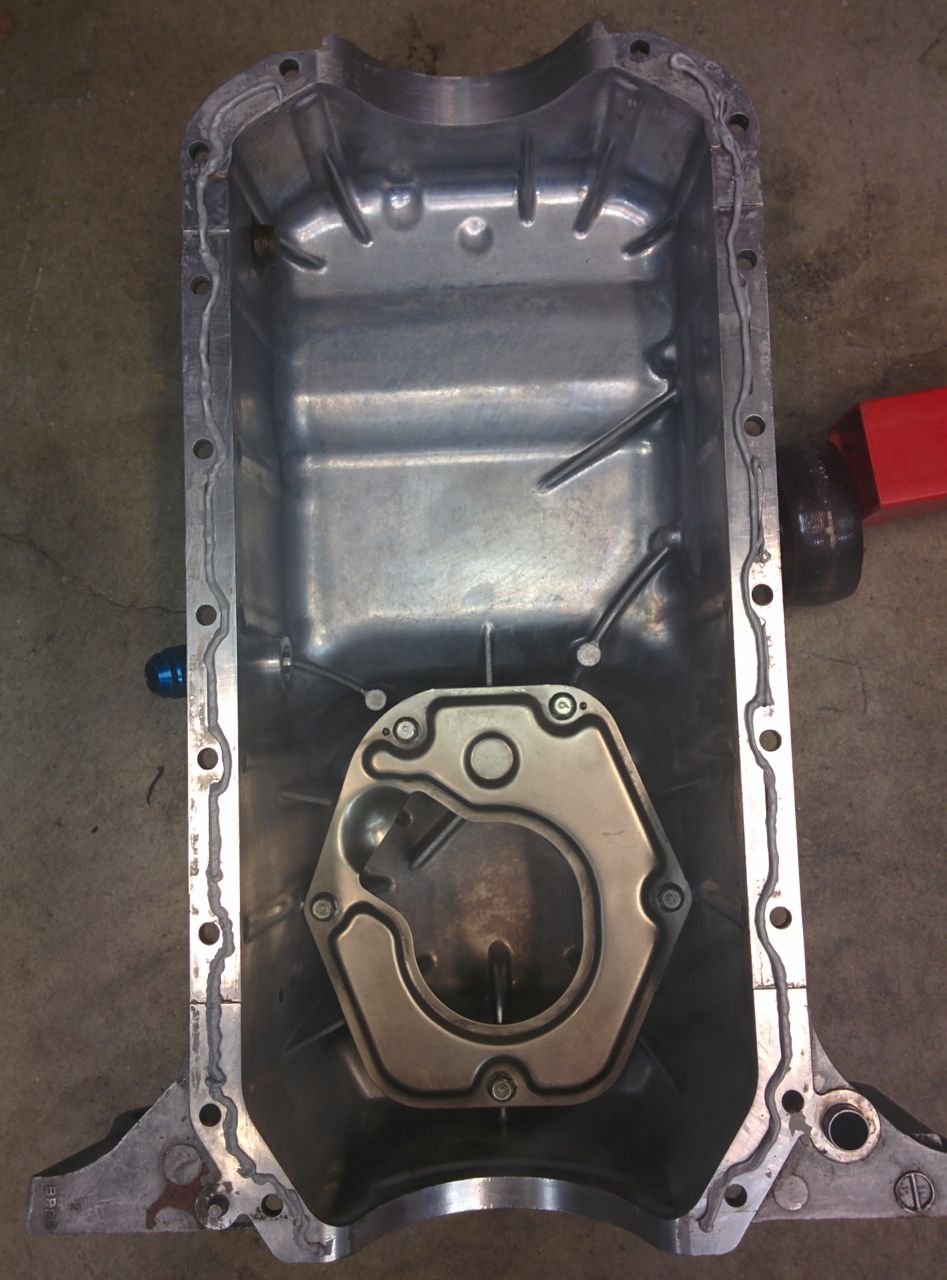
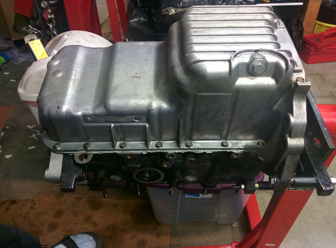
And then the pan went on. Bye-bye rods! You're really pretty, but I hope I don't see you again for a long time!
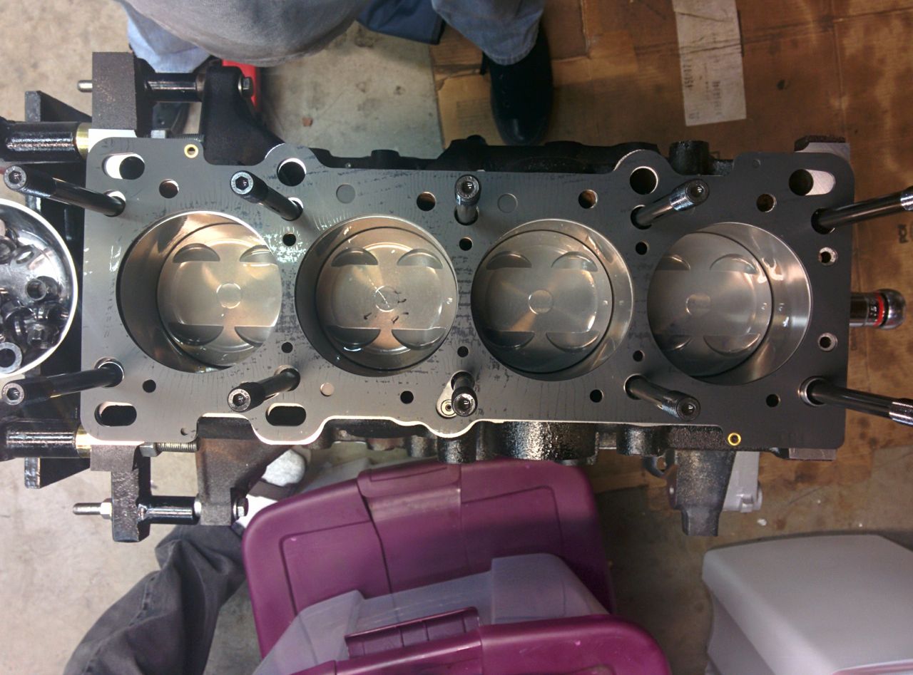
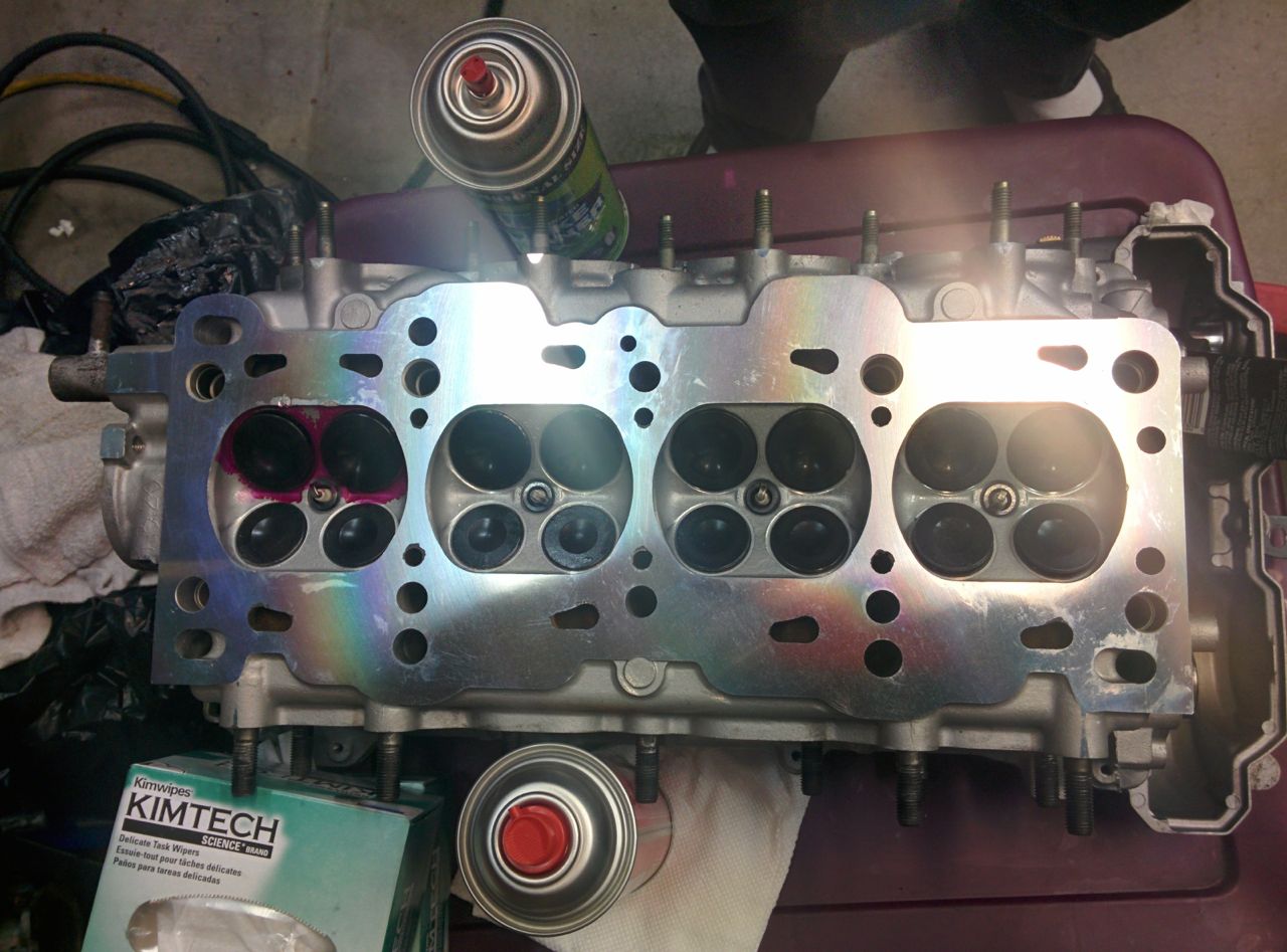
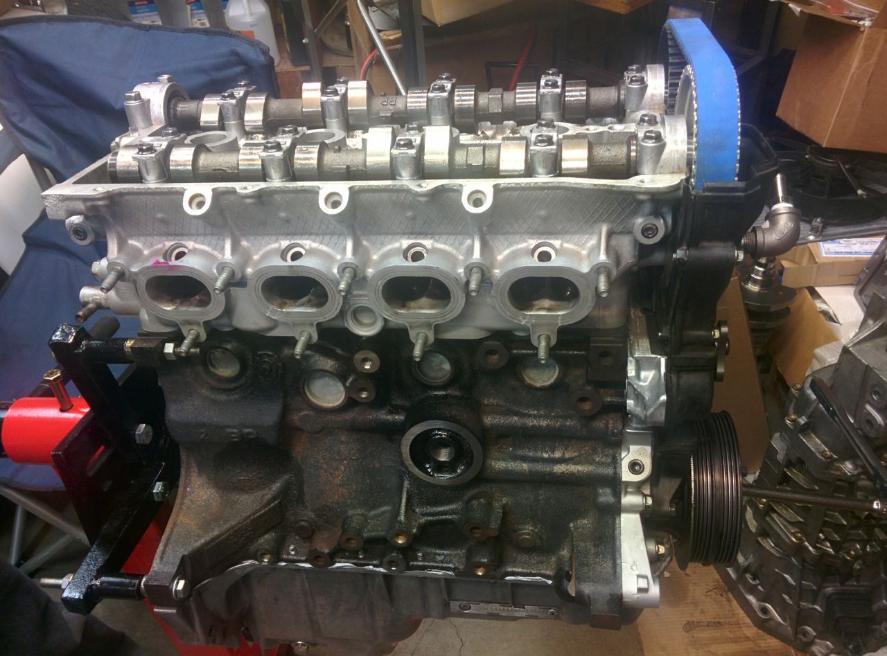
Then it was time to put the head on. First I needed to clean all the anti-rust WD40/etc off the top of the engine block.
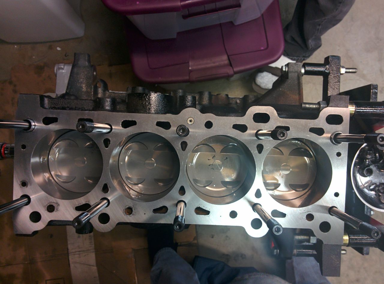
And lay on the head gasket:
And then clean all the oil residue off the head that had leaked down while working on the valves/etc. I've gone through 7 or 8 cans of brake cleaner on the build so far.
And poof! Bye-bye pistons, same as the rods!
--Ian
So later in the afternoon, I located an oil pump O-ring (huge thanks to Savington!). With that, the assembly could continue. All that and I didn't get a picture of it, but it's not all that interesting to look at.
So first the oil pump goes on the block:
And then I squirted gray RTV on a bunch of things:
And then the pan went on. Bye-bye rods! You're really pretty, but I hope I don't see you again for a long time!
Then it was time to put the head on. First I needed to clean all the anti-rust WD40/etc off the top of the engine block.
And lay on the head gasket:
And then clean all the oil residue off the head that had leaked down while working on the valves/etc. I've gone through 7 or 8 cans of brake cleaner on the build so far.
And poof! Bye-bye pistons, same as the rods!
--Ian
Reply
0
0
12-07-2014, 01:45 PM
#67
Elite Member
Thread Starter
Join Date: Mar 2007
Location: Santa Clara, CA
Posts: 5,165
Total Cats: 855
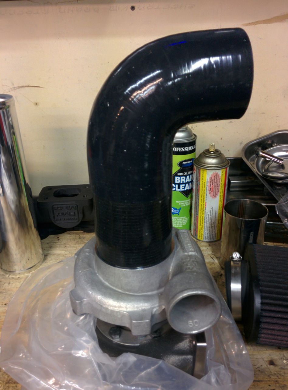
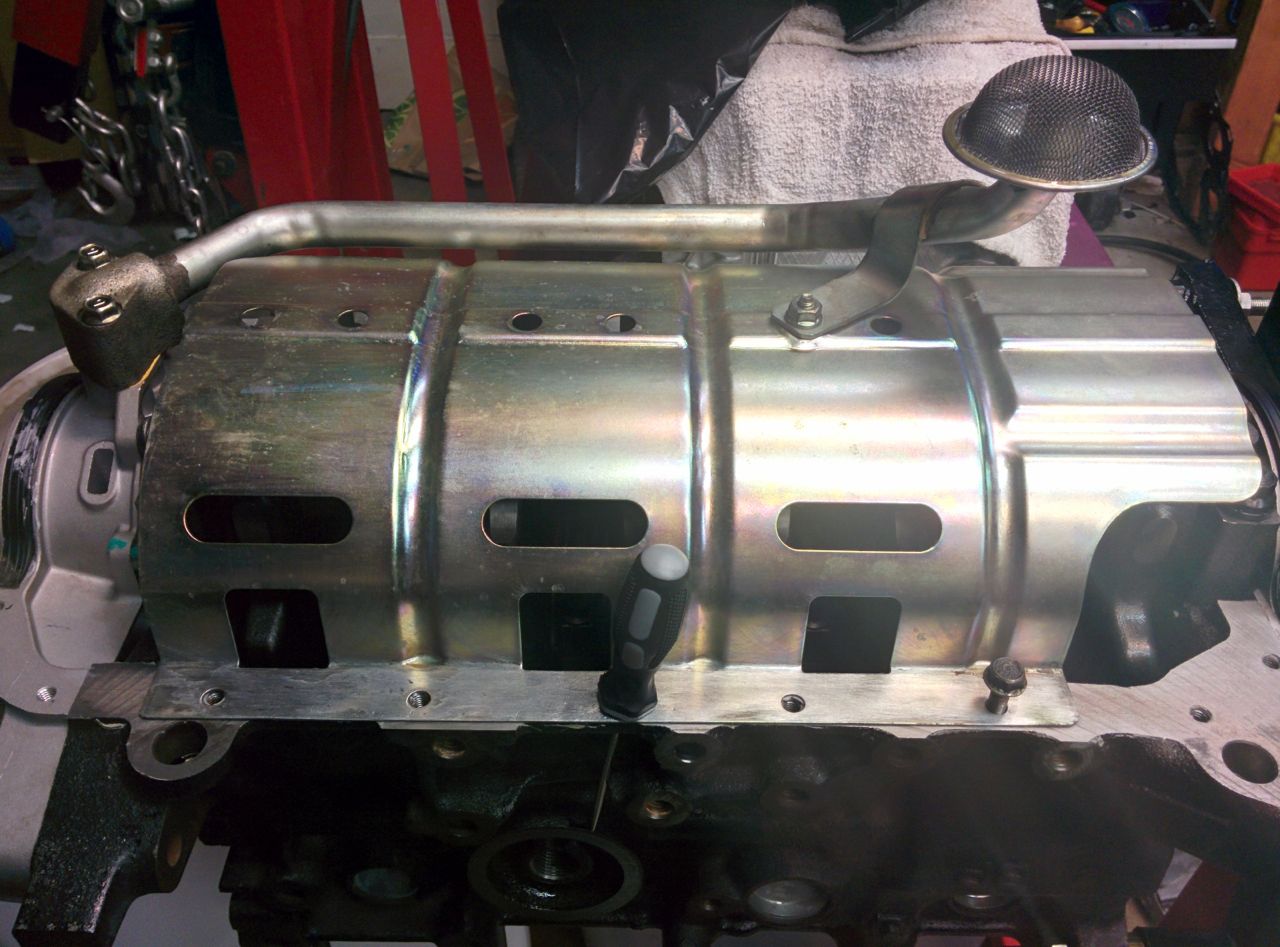
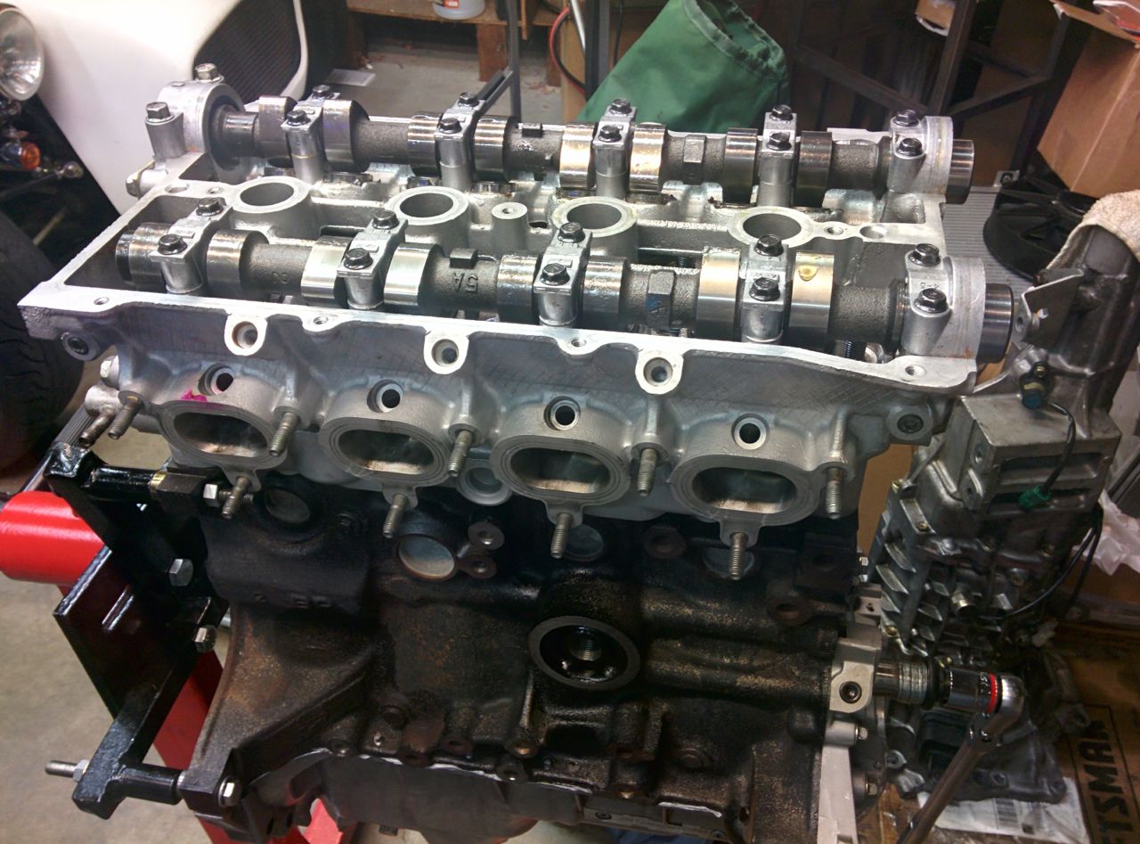
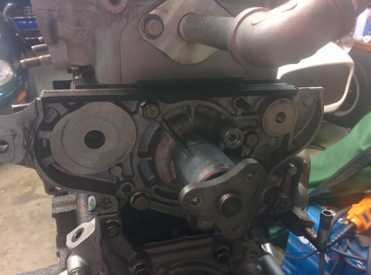
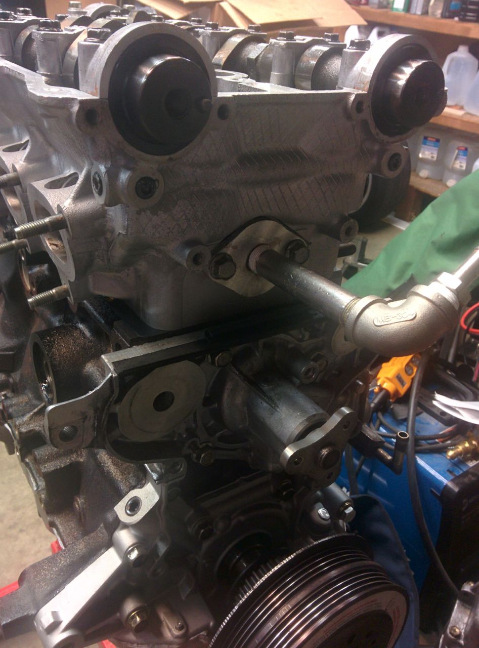
But I wasn't done yet! Time to put some things on the front of the engine! I'm reusing the water pump from before, it's only got 10K miles on it:
And this is my turbo water supply:
And then a bunch of other parts got bolted on without in-progress pictures, including the fancy new adjustable cam gear on the intake cam:
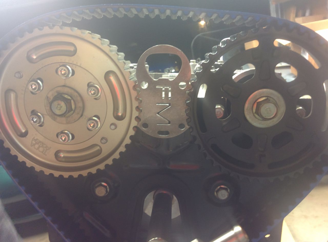
Then a bit of a setback. Installing the ATI super damper is kind of a PITA -- you lube up the crank with anti-seize and press it on with a bolt in the crank threads. Since the timing belt gear and the damper are pre-assembled, the timing belt needs to go on at hte same time, along with the lower timing belt cover. Make sure everything underneath that cover is installed and torqued, because taking it off again is a pain.
Alas, I wound up having to take it off again, because thew woodruff key slipped, and the pulley started carving it up:
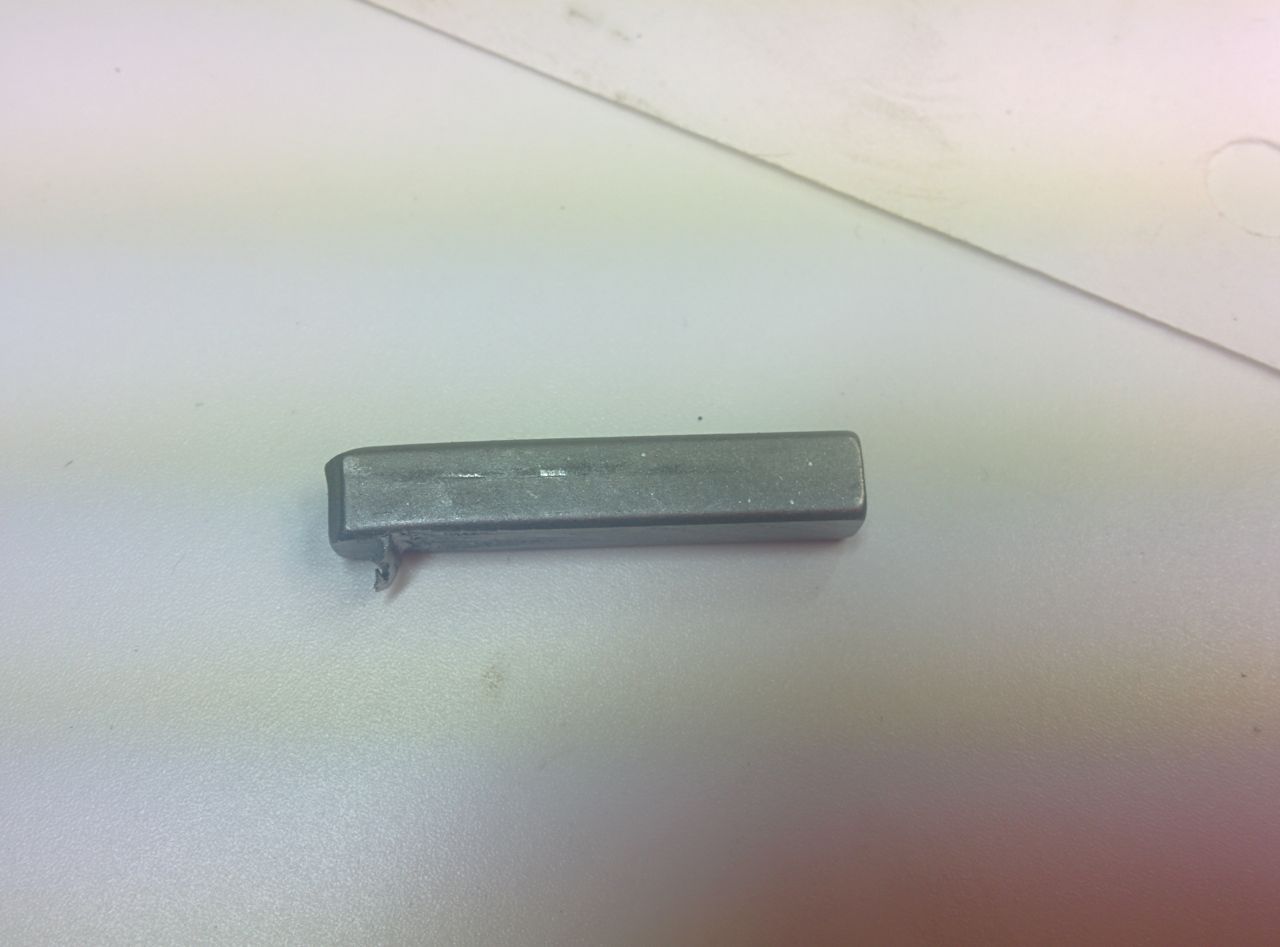
So I wound up reusing my old woodruff key. Good thing I had it as a spare:
And then throw the vlave cover on and call it a night!
--Ian
And this is my turbo water supply:
And then a bunch of other parts got bolted on without in-progress pictures, including the fancy new adjustable cam gear on the intake cam:
Then a bit of a setback. Installing the ATI super damper is kind of a PITA -- you lube up the crank with anti-seize and press it on with a bolt in the crank threads. Since the timing belt gear and the damper are pre-assembled, the timing belt needs to go on at hte same time, along with the lower timing belt cover. Make sure everything underneath that cover is installed and torqued, because taking it off again is a pain.
Alas, I wound up having to take it off again, because thew woodruff key slipped, and the pulley started carving it up:
So I wound up reusing my old woodruff key. Good thing I had it as a spare:
And then throw the vlave cover on and call it a night!
--Ian
Reply
0
0
12-08-2014, 03:32 PM
#68
Elite Member
Thread Starter
Join Date: Mar 2007
Location: Santa Clara, CA
Posts: 5,165
Total Cats: 855
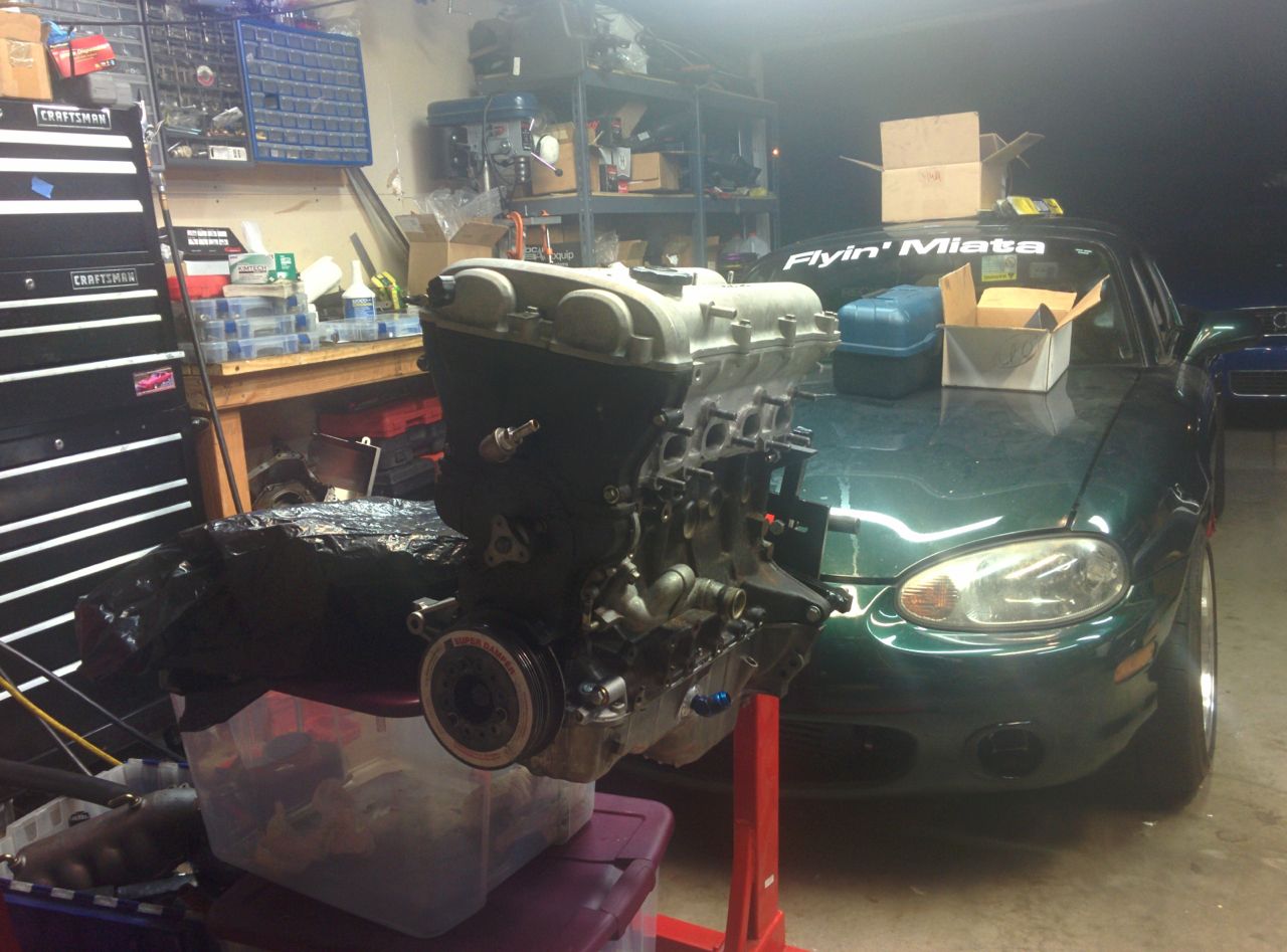
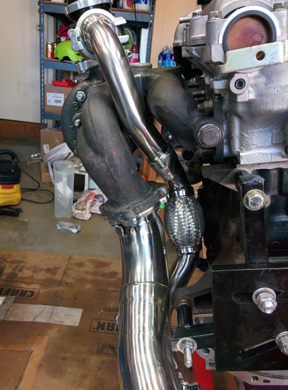
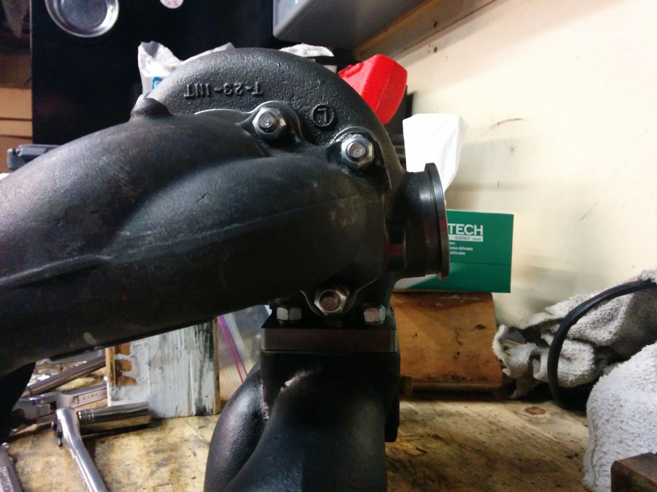
So on Sunday afternoon I mocked up the various exhaust pieces to check clearances and figure out where to install the EGT sender and to line up the turbo for clocking. This is all temporary, one or two nuts, no gaskets, and pre-clocking:
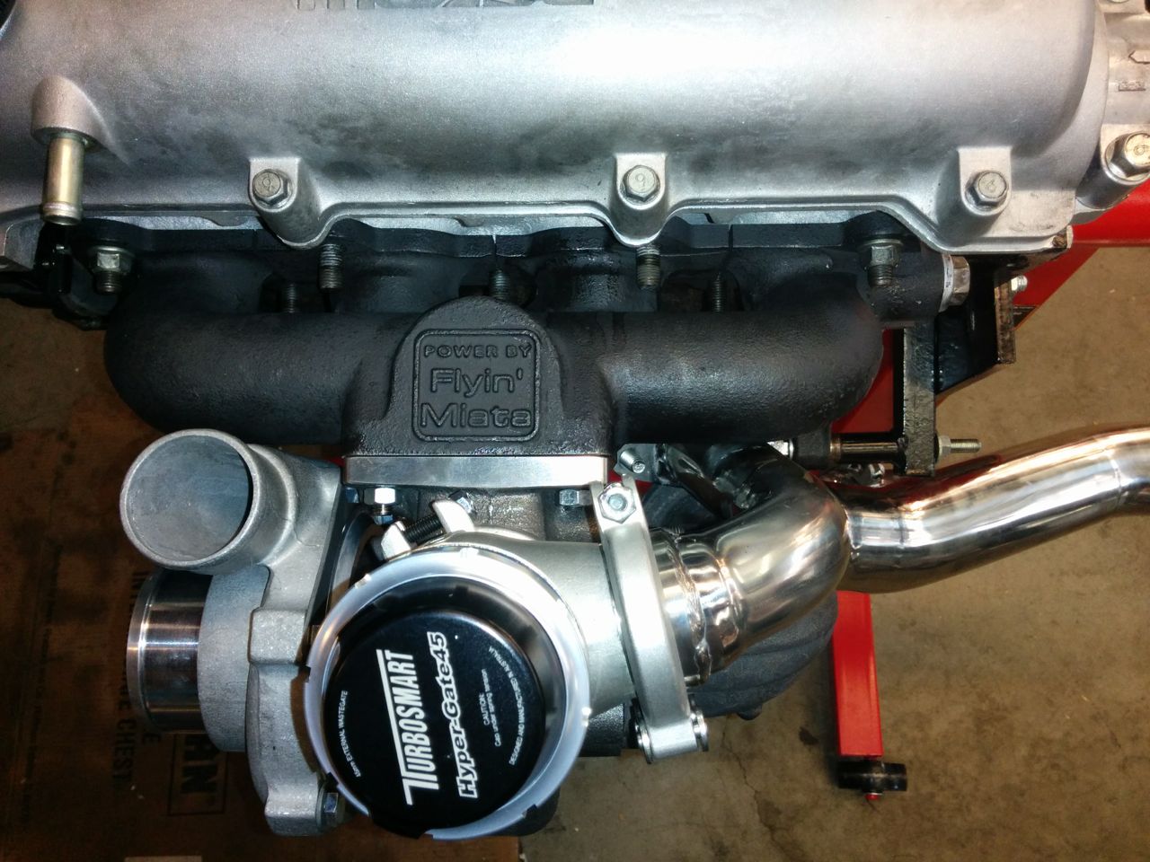
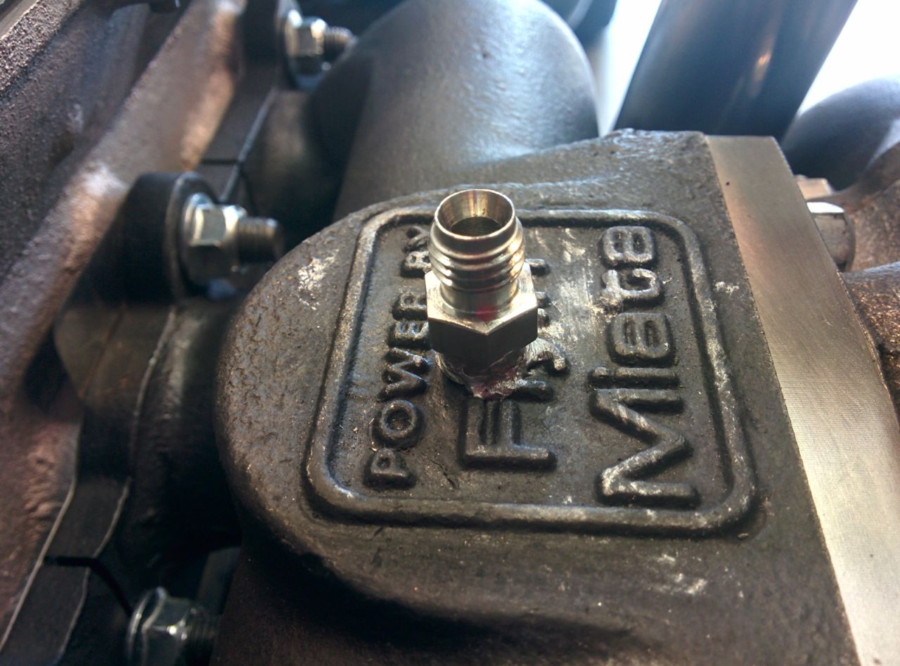
I wound up concluding that the EGR sender needs to go on top, in the flat bit where it says "Power by Flyin' Miata". That's kind of ugly, but I can't see anywhere else on the manifold to put it, there's really not enough room on the bottom, and I want the EGT to be pre-turbo.
Then I pulled out the new EGT sender to install it (switching to an AutoMeter EGT gauge, rather than the Westach dual EGT gauge that had been somewhat spotty and unreliable before) and discovered that it's a very loose fit for the sender, and you're supposed to use a setscrew to hold it in the fitting? WTF? Apparently the compression fittings are an extra-cost option these days. So I need to go figure out a solution for that.
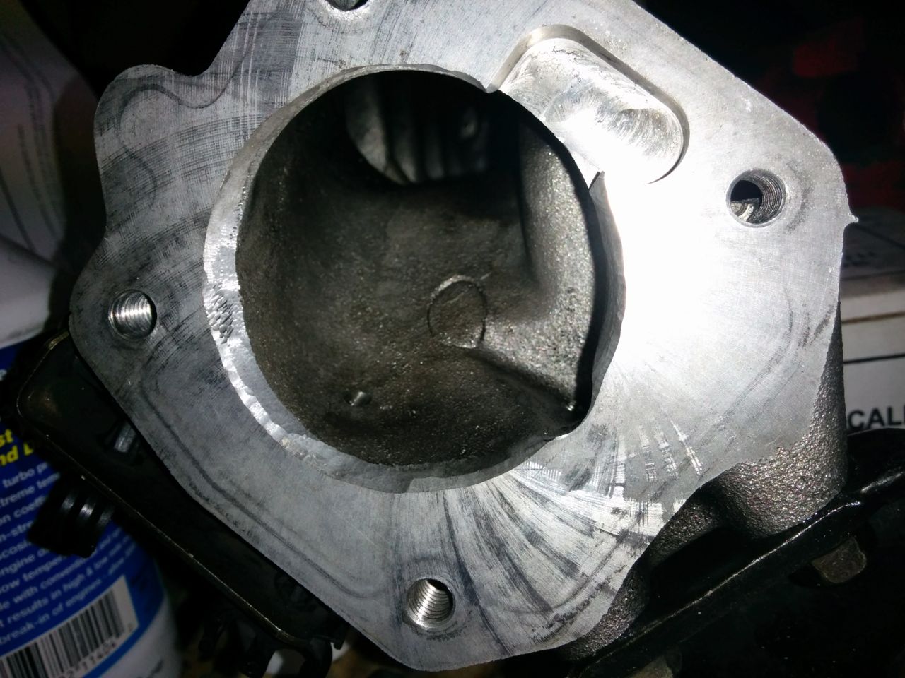
So then I went to put the Skunk2 throttle body on the manifold and noticed the lip where the the larger-than-stock-diameter throttle meets the stock-diameter 99 intake manifold (yes, I'm using a stock, VICS-intact, 99 intake manifold). That will never do, so I went at it with a grinder and some carbide bits. First time I've tried porting anything, so it's not super pretty but I think it'll do.
Then I put all the intake bits on. Didn't get a shot of that, but it doesn't look all that different from most other Miata motors.
--Ian
I wound up concluding that the EGR sender needs to go on top, in the flat bit where it says "Power by Flyin' Miata". That's kind of ugly, but I can't see anywhere else on the manifold to put it, there's really not enough room on the bottom, and I want the EGT to be pre-turbo.
Then I pulled out the new EGT sender to install it (switching to an AutoMeter EGT gauge, rather than the Westach dual EGT gauge that had been somewhat spotty and unreliable before) and discovered that it's a very loose fit for the sender, and you're supposed to use a setscrew to hold it in the fitting? WTF? Apparently the compression fittings are an extra-cost option these days. So I need to go figure out a solution for that.
So then I went to put the Skunk2 throttle body on the manifold and noticed the lip where the the larger-than-stock-diameter throttle meets the stock-diameter 99 intake manifold (yes, I'm using a stock, VICS-intact, 99 intake manifold). That will never do, so I went at it with a grinder and some carbide bits. First time I've tried porting anything, so it's not super pretty but I think it'll do.
Then I put all the intake bits on. Didn't get a shot of that, but it doesn't look all that different from most other Miata motors.
--Ian
Reply
0
0
12-08-2014, 03:53 PM
#69
Elite Member
iTrader: (16)

Join Date: Oct 2006
Location: Las Cruces, NM
Posts: 1,647
Total Cats: 524
Your build it looking great! When you port the manifold for the larger TB, you want to make the port open up to the new size and have a gradual taper, not a short lip that goes up the the larger size. I ported mine with a taper about two inches in.
Here are pics from my https://www.miataturbo.net/build-thr...-62620/page24/:

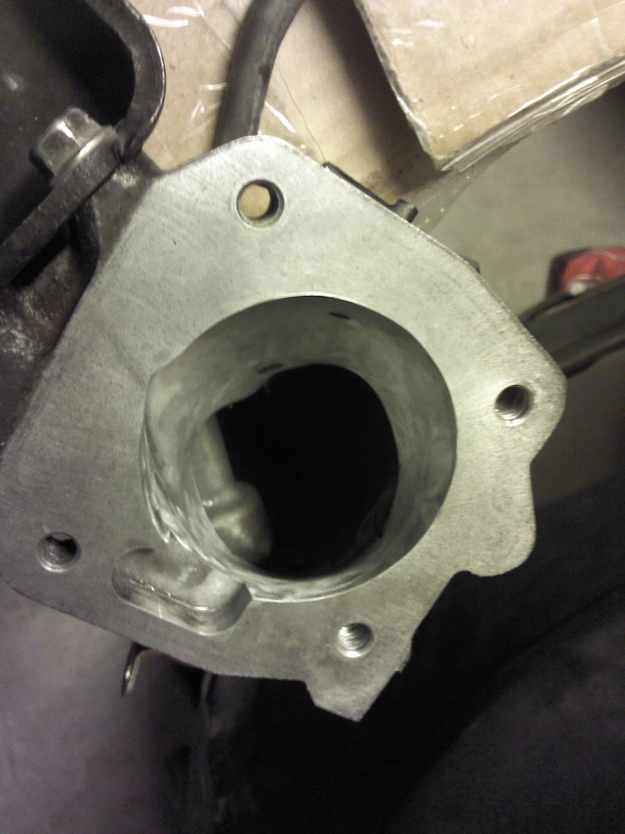

Here are pics from my https://www.miataturbo.net/build-thr...-62620/page24/:
Reply
0
0
12-08-2014, 03:56 PM
#70
Elite Member
iTrader: (37)
Join Date: Apr 2010
Location: Very NorCal
Posts: 10,441
Total Cats: 1,899
Wow, it looks like there is a lot more material to remove on the NB1 manifold than the squaretop. Any chance you shot a pic with layout lines before you started grinding?
I also did the same as Ari, longer transition is better transition.
Looks great! Of course, I've always loved external gates
I also did the same as Ari, longer transition is better transition.
Looks great! Of course, I've always loved external gates
Reply
0
0
12-08-2014, 06:01 PM
#71
Elite Member
Thread Starter
Join Date: Mar 2007
Location: Santa Clara, CA
Posts: 5,165
Total Cats: 855
The porting I did goes in about 3/4 of an inch or so. I stopped there because I was worried about breaking through the casting, there was one spot that looked like it might be close to getting thin. I'll take another look at it.
Alas, I didn't take any photos before I started grinding. I do have a spare upper intake manifold in a box that I could match it up against, though.
--Ian
Alas, I didn't take any photos before I started grinding. I do have a spare upper intake manifold in a box that I could match it up against, though.
--Ian
Reply
0
0
12-08-2014, 06:07 PM
#72
Elite Member
iTrader: (37)
Join Date: Apr 2010
Location: Very NorCal
Posts: 10,441
Total Cats: 1,899
Ehh, photo isn't important. I was just surprised by the amount of meat that was removed. I did mine with a dremel so throw was limited, but then I think I had less material to remove.
Reply
0
0
12-10-2014, 01:54 PM
#74
Elite Member
Thread Starter
Join Date: Mar 2007
Location: Santa Clara, CA
Posts: 5,165
Total Cats: 855
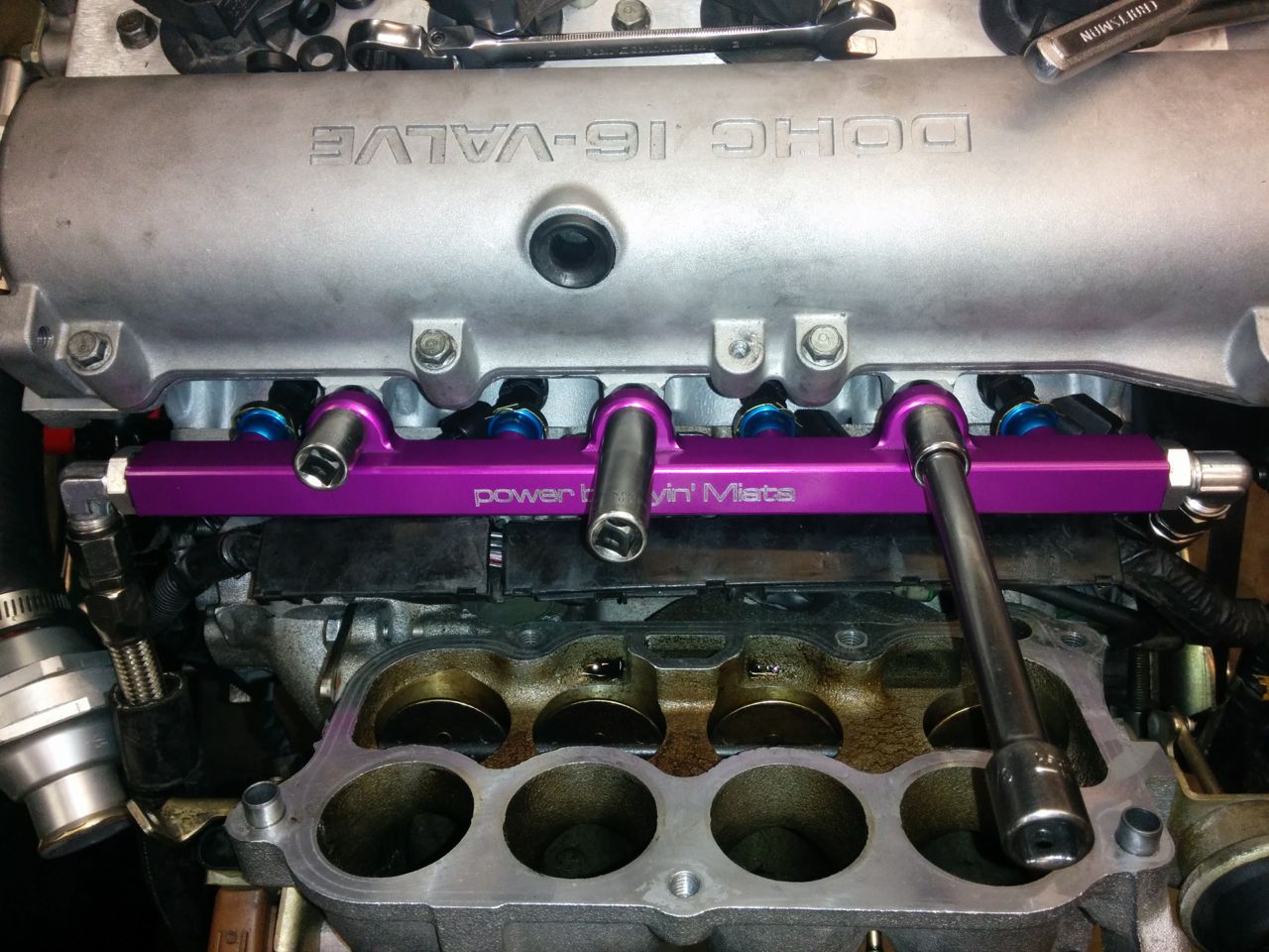
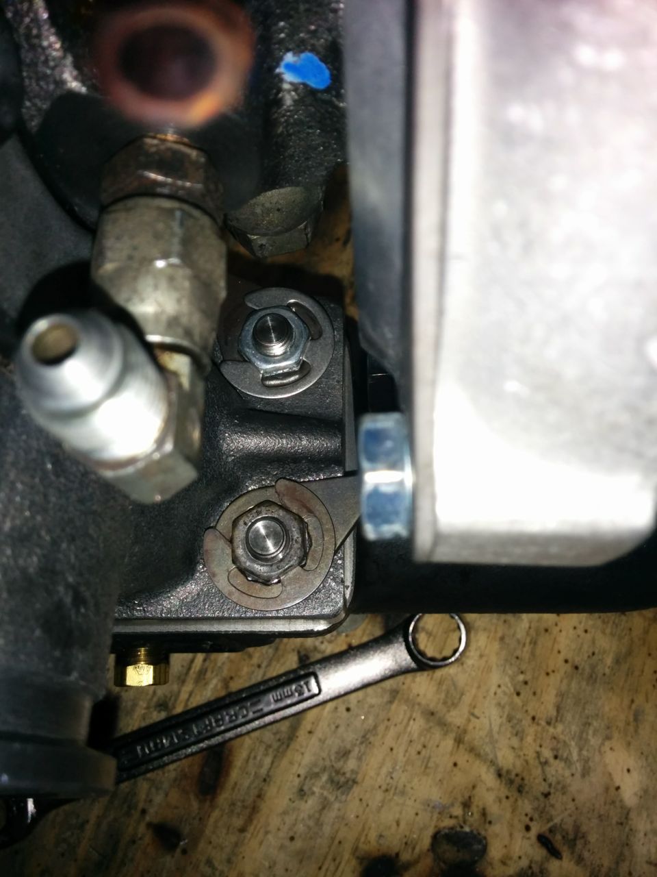
The FM fuel rail I have is low on clearance for the factory fuel rail bolts with 12mm heads. With the bolts in the position that they want to sit in, there isn't *quite* enough room to fit a socket on it without conflicting with the wall of the rail. The sockets fit when the bolts are loose, but once I tighten one of them, I often can't get the others to go on. I keep thinking I should replace the bolts with allen-key hex bolts, but haven't gotten around to it.
Fortunately I have lots of 12mm sockets, so here's my short-term hack solution:
--Ian
Fortunately I have lots of 12mm sockets, so here's my short-term hack solution:
--Ian
Reply
0
0
12-21-2014, 02:54 AM
#75
Elite Member
Thread Starter
Join Date: Mar 2007
Location: Santa Clara, CA
Posts: 5,165
Total Cats: 855
Some progress from last weekend which I never got around to posting, plus a teeny bit of stuff this evening. First I needed to drill and tap the new manifold for an EGT probe. Alas, the stupid AutoMeter EGT gauge that I'm switching to came with fitting that uses a setscrew to hold the probe into the manifold, rather than a compression fitting. Grr. I ordered a compression fitting for it, but because it's NPT it needs to be tapped so that the fitting goes in an appropriate depth, but no more or it won't seal. Since I'm not going to re-tap it without cleaning it out properly, this meant the engine wasn't going into the car until the fitting shows up. So I drilled & tapped to a conservative depth, and went with the plan to put the turbo on the engine (fairly easy to reverse if necessary), but not the engine in the car.
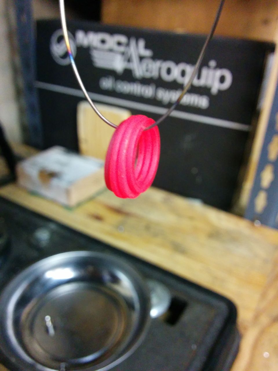
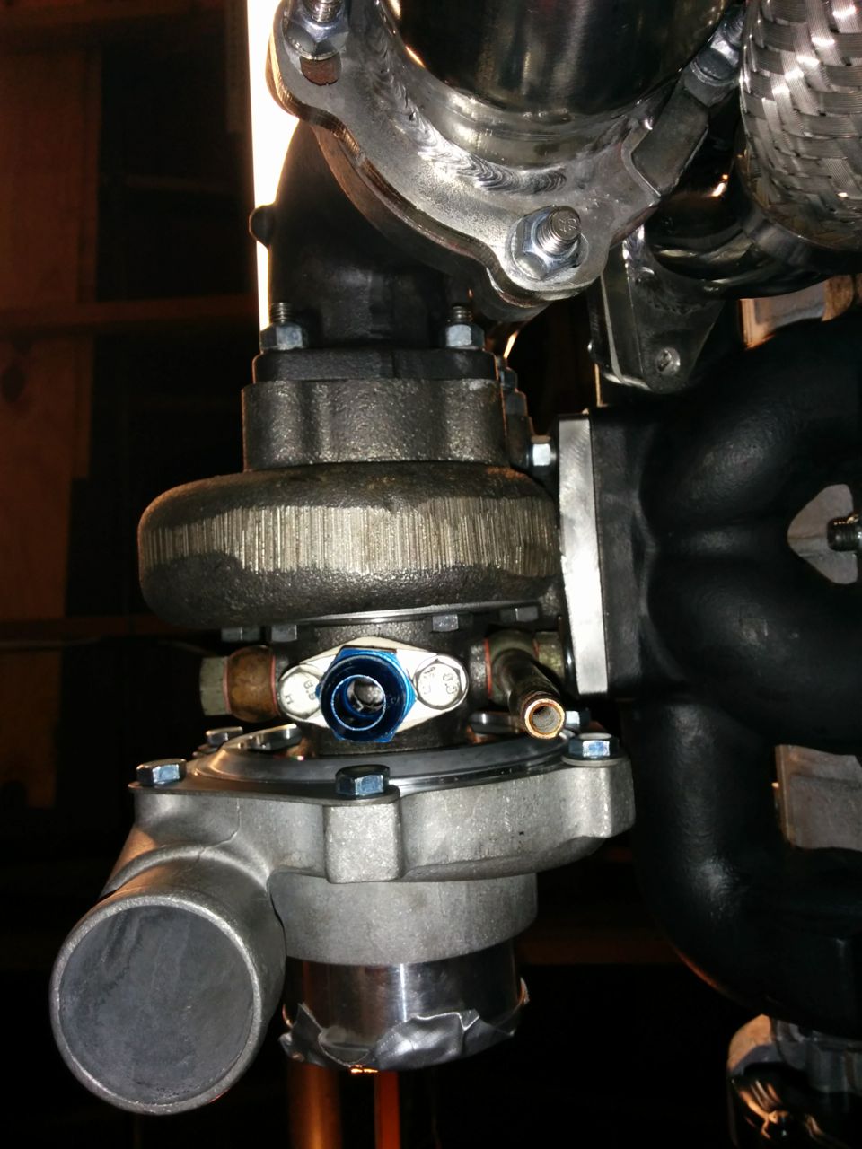
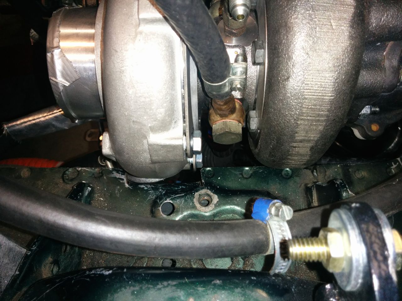
So next I needed to mount the various water and oil fittings onto the new turbo. This means re-annealing the copper crush washers on the banjo fittings, which meant I got to play with the MAPP gas torch! OK, they probably didn't need to be *quite* as hot as I got them, but hey, at least I didn't melt them.
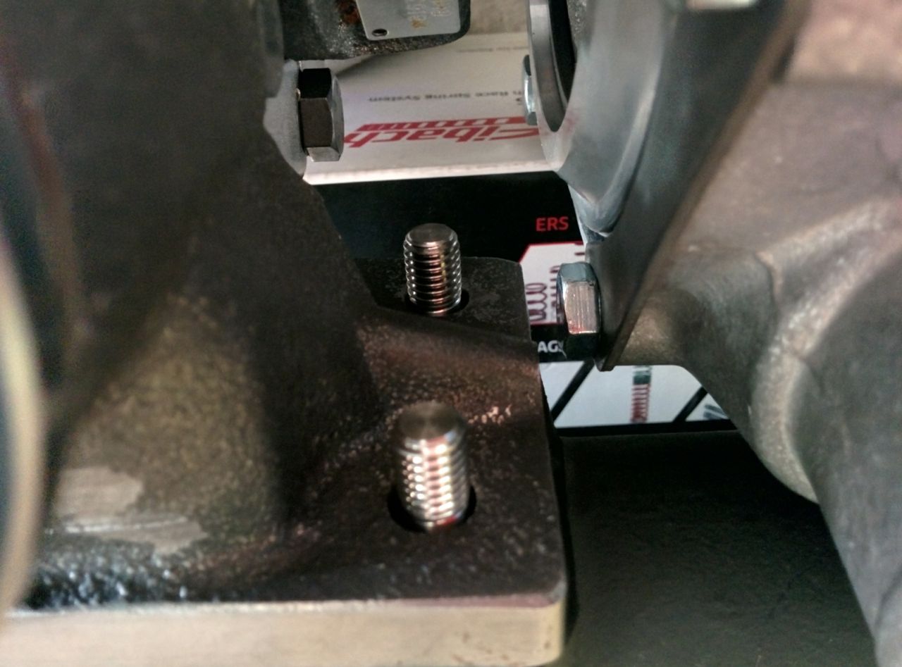
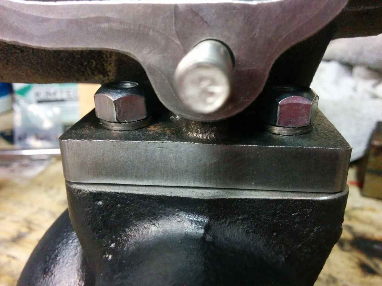
With that done, it was time to mount the turbo to the manifold. The stage 8 fasteners fit nicely on the front two nuts:
But there was no way they were going to go onto the rear two, not without substantial grinding on the casting. This is the ATP turbine housing with the integral EWG V-band port, and apparently it has slightly less clearance around these nuts than the Garrett ones do. I'm glad I'm not trying to use 10mm studs here!
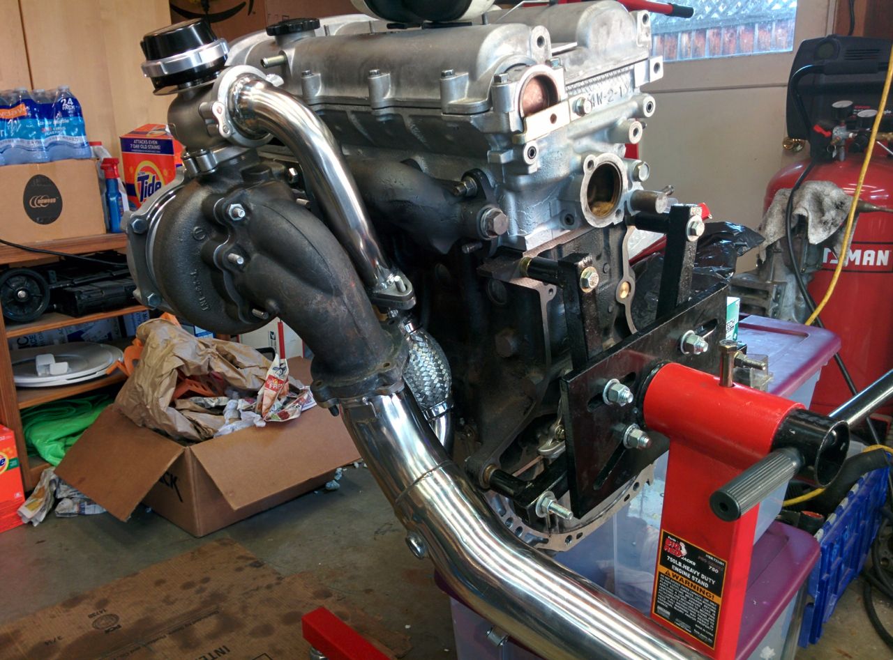
Turbo mounted:
Downpipe casting mounted:
And then it was time to bolt the manifold to the car. There's a brass plug in the hole for the EGT probe -- just a temporary measure.
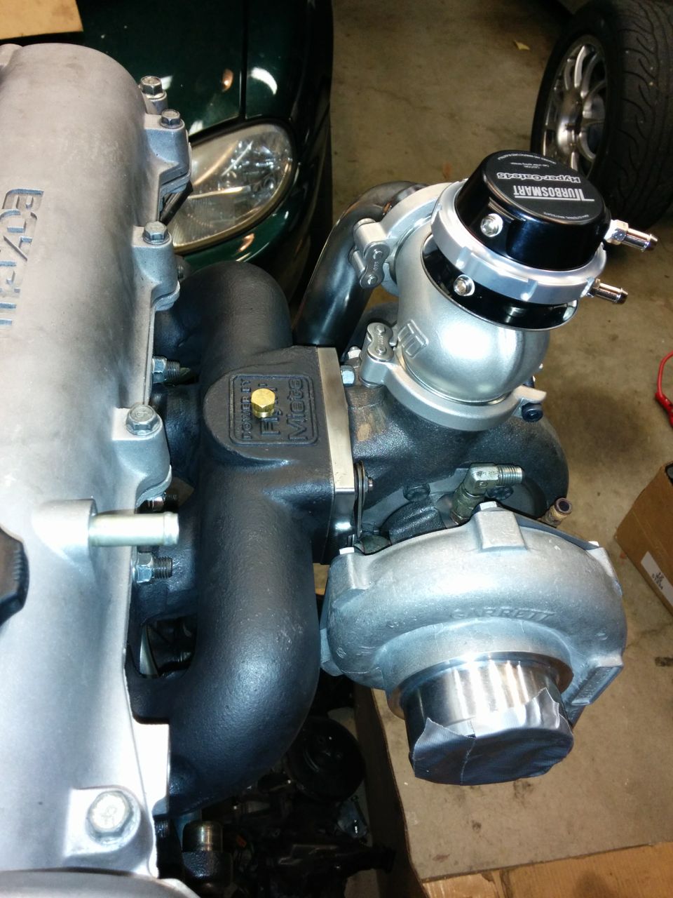
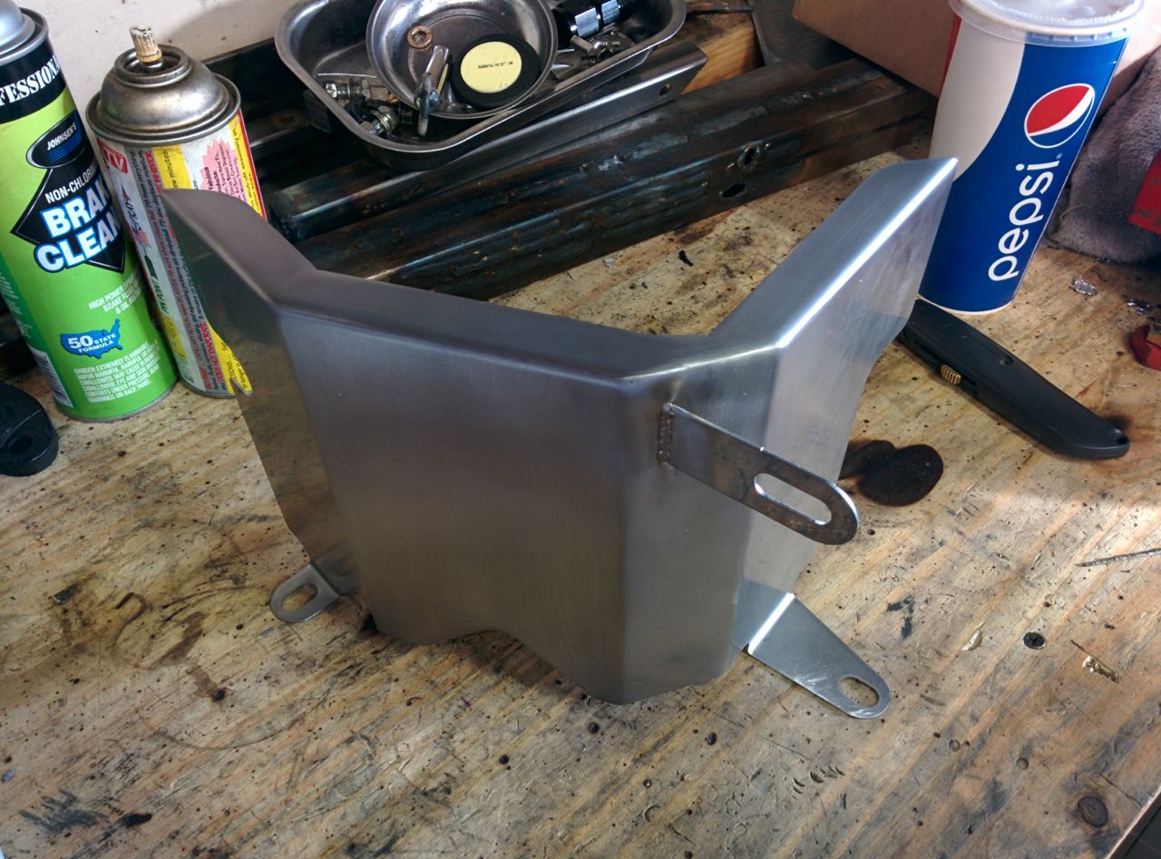
I also put on the rest of the exhaust plumbing, it's all mounted loosely right now, about half a turn from being tight. The holes on the downpipe are slotted so that it can rotate about 30 degrees to align the exhaust properly. Looks similar to the earlier test-fitting, but it's got the proper nuts/etc on it now.
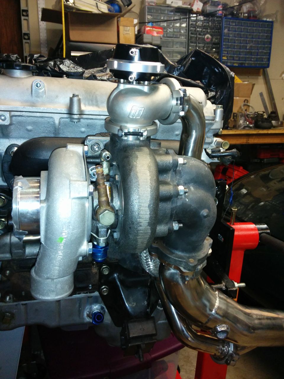
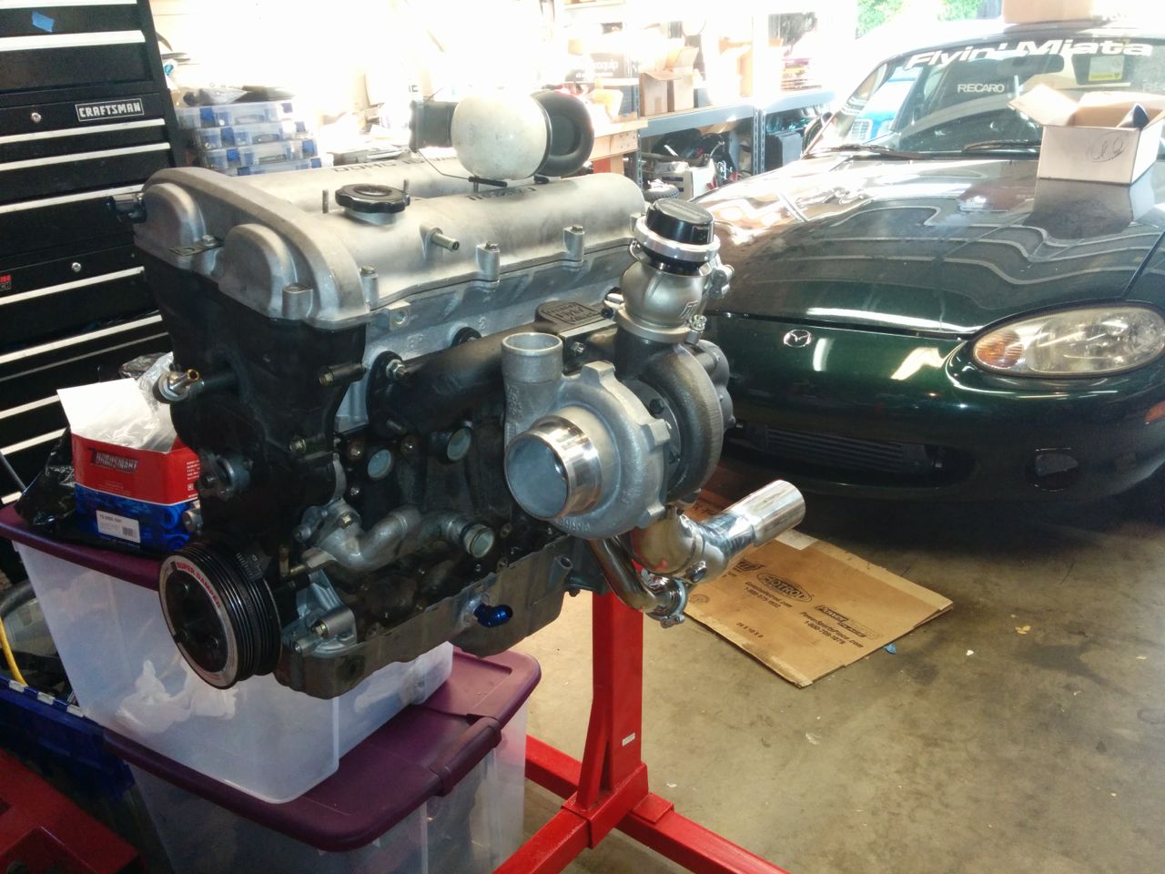
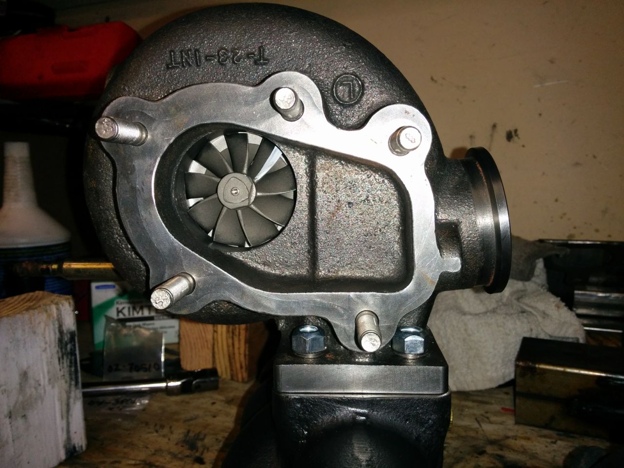
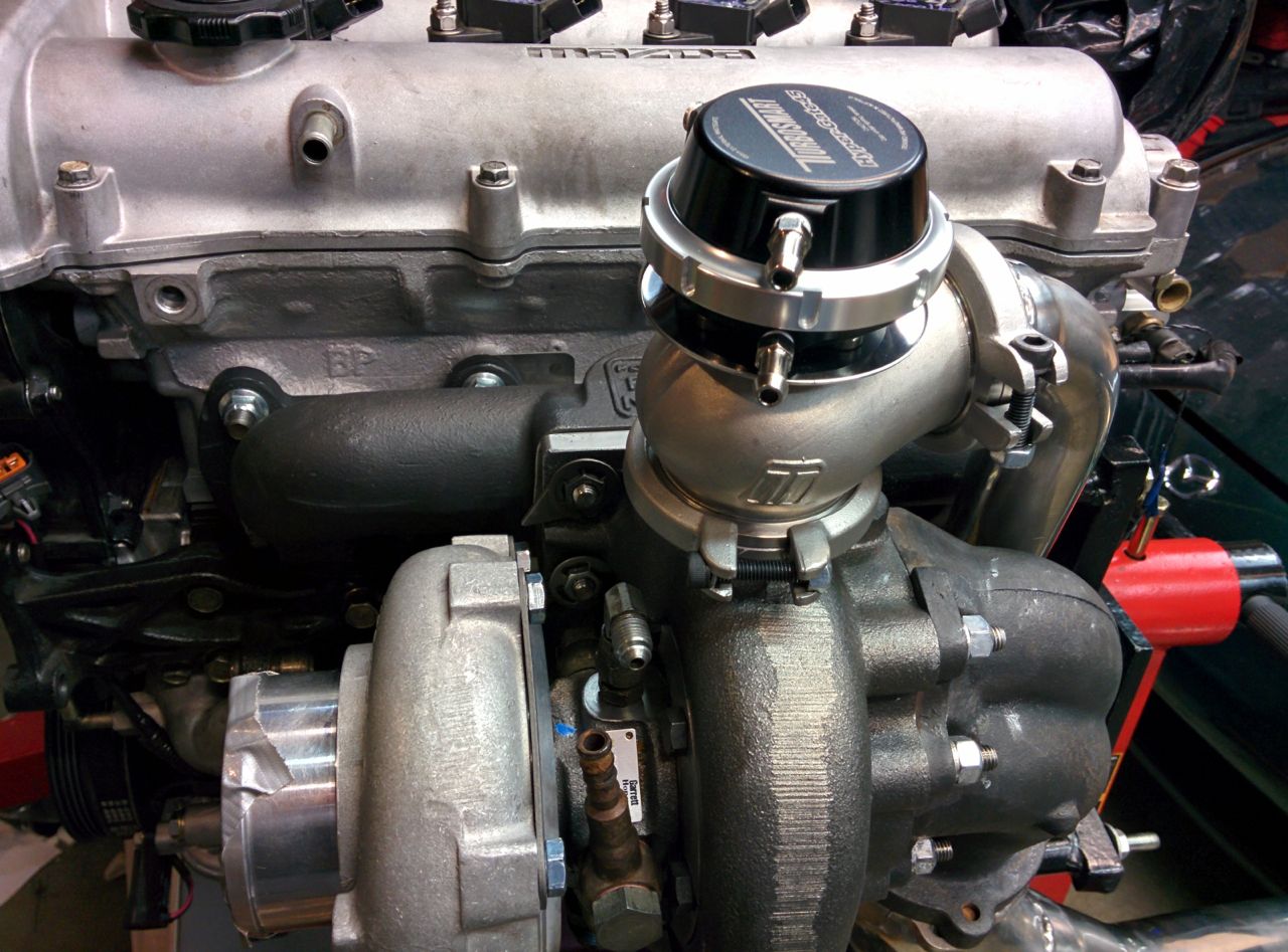
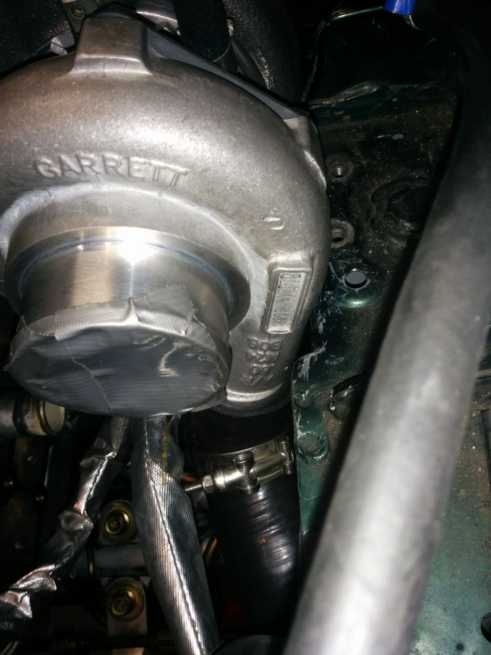
And a view of the turbo you really can't get when it's in the car:
My goal for Sunday is to get the engine in the car!
--Ian
So next I needed to mount the various water and oil fittings onto the new turbo. This means re-annealing the copper crush washers on the banjo fittings, which meant I got to play with the MAPP gas torch!
OK, they probably didn't need to be *quite* as hot as I got them, but hey, at least I didn't melt them.With that done, it was time to mount the turbo to the manifold. The stage 8 fasteners fit nicely on the front two nuts:
But there was no way they were going to go onto the rear two, not without substantial grinding on the casting. This is the ATP turbine housing with the integral EWG V-band port, and apparently it has slightly less clearance around these nuts than the Garrett ones do. I'm glad I'm not trying to use 10mm studs here!
Turbo mounted:
Downpipe casting mounted:
And then it was time to bolt the manifold to the car. There's a brass plug in the hole for the EGT probe -- just a temporary measure.
I also put on the rest of the exhaust plumbing, it's all mounted loosely right now, about half a turn from being tight. The holes on the downpipe are slotted so that it can rotate about 30 degrees to align the exhaust properly. Looks similar to the earlier test-fitting, but it's got the proper nuts/etc on it now.
And a view of the turbo you really can't get when it's in the car:
My goal for Sunday is to get the engine in the car!
--Ian
Reply
0
0
12-21-2014, 02:04 PM
#77
Elite Member
Thread Starter
Join Date: Mar 2007
Location: Santa Clara, CA
Posts: 5,165
Total Cats: 855
As for the heater line, I've got heat-reflective fiberglass tape to put over it, plus FM supplies a sheet metal heat shield that goes around the turbo.
--Ian
Reply
0
0
12-22-2014, 04:21 AM
#78
Elite Member
Thread Starter
Join Date: Mar 2007
Location: Santa Clara, CA
Posts: 5,165
Total Cats: 855
Made a bunch of progress today. First on the list was the EGT fitting -- I ordered "yor-loc" compression fittings from mcmaster (clones of swagelok), unfortunately they're designed for tubes, not for EGT probes. Real swageloks come in a "BT" or "bored through" version, but the mcmaster ones don't, so I needed to drill it.
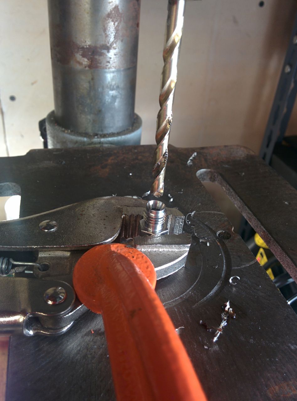
(I really need to get a vise for the drill press. Hell, for that matter I really need to get a better drill press, the runout on this one is terrible).
And then it went in the manifold:
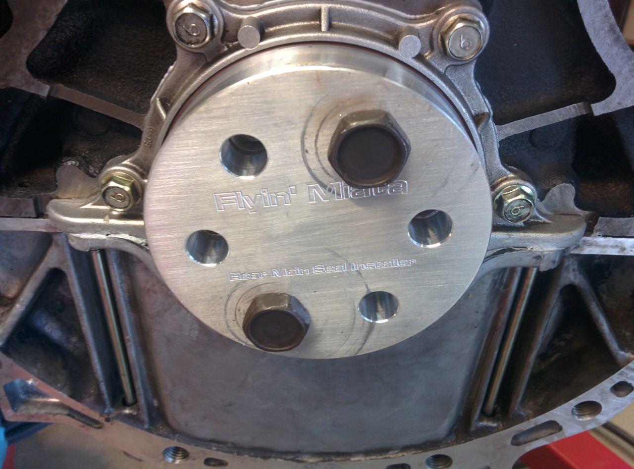
Then it was time to get out the hoist again, take the engine off the stand, and attach things to the back. Like the rear main seal (don't forget this!)
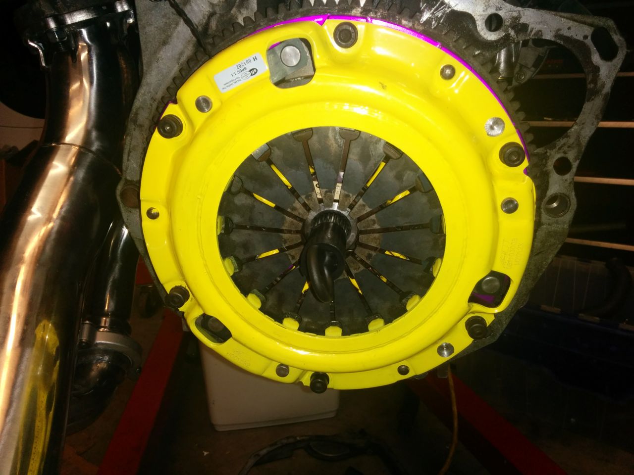
And then the flywheel and the clutch. I forgot to take a picture of the flywheel, oh well. You've seen it before.
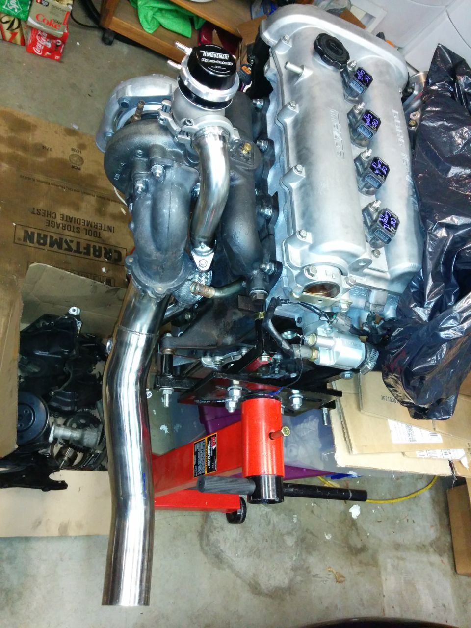
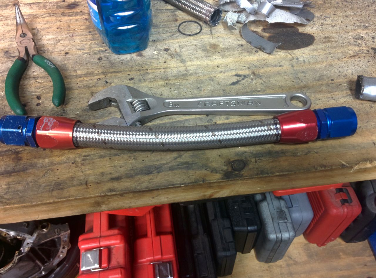
The new turbo geometry is slightly different from the old one, and the oil drain hose was about half an inch too short. So I made a new one:
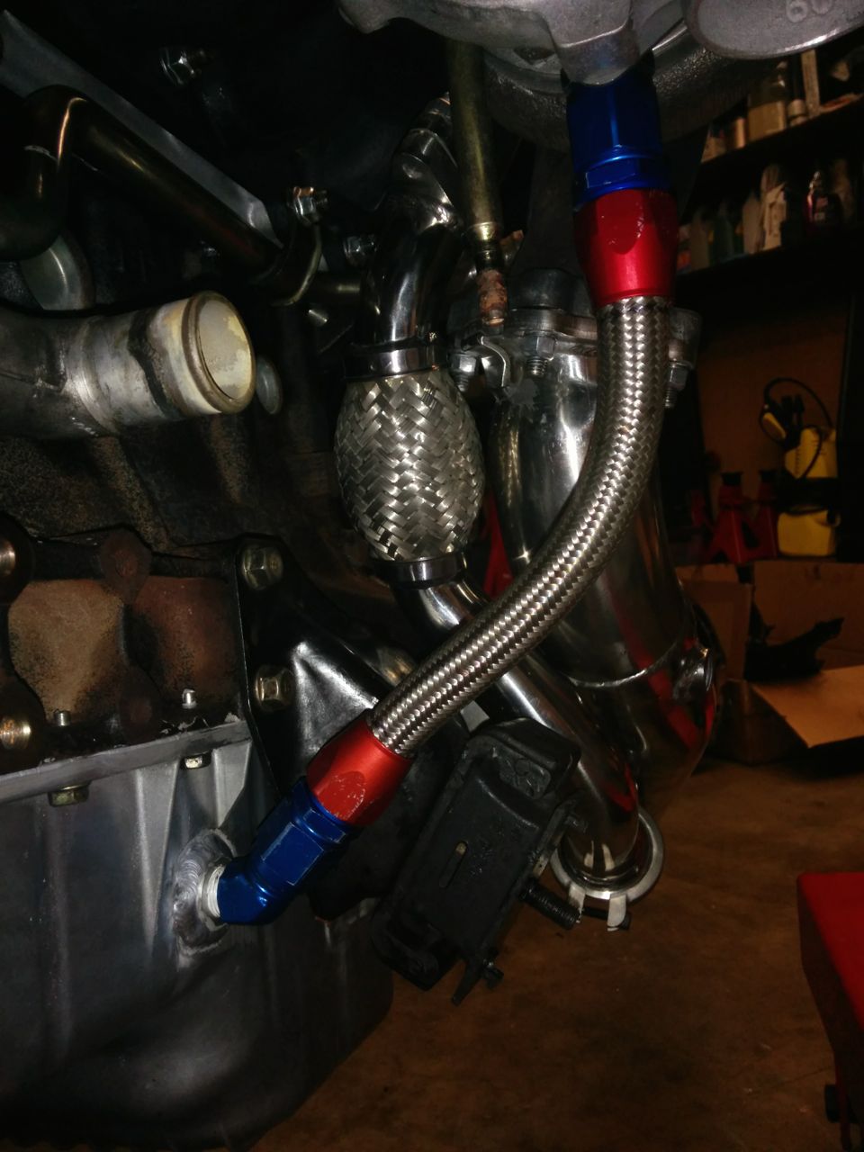
And then it went on the engine:
--Ian
(I really need to get a vise for the drill press. Hell, for that matter I really need to get a better drill press, the runout on this one is terrible).
And then it went in the manifold:
Then it was time to get out the hoist again, take the engine off the stand, and attach things to the back. Like the rear main seal (don't forget this!)
And then the flywheel and the clutch. I forgot to take a picture of the flywheel, oh well. You've seen it before.
The new turbo geometry is slightly different from the old one, and the oil drain hose was about half an inch too short. So I made a new one:
And then it went on the engine:
--Ian
Reply
0
0
12-22-2014, 04:28 AM
#79
Elite Member
Thread Starter
Join Date: Mar 2007
Location: Santa Clara, CA
Posts: 5,165
Total Cats: 855
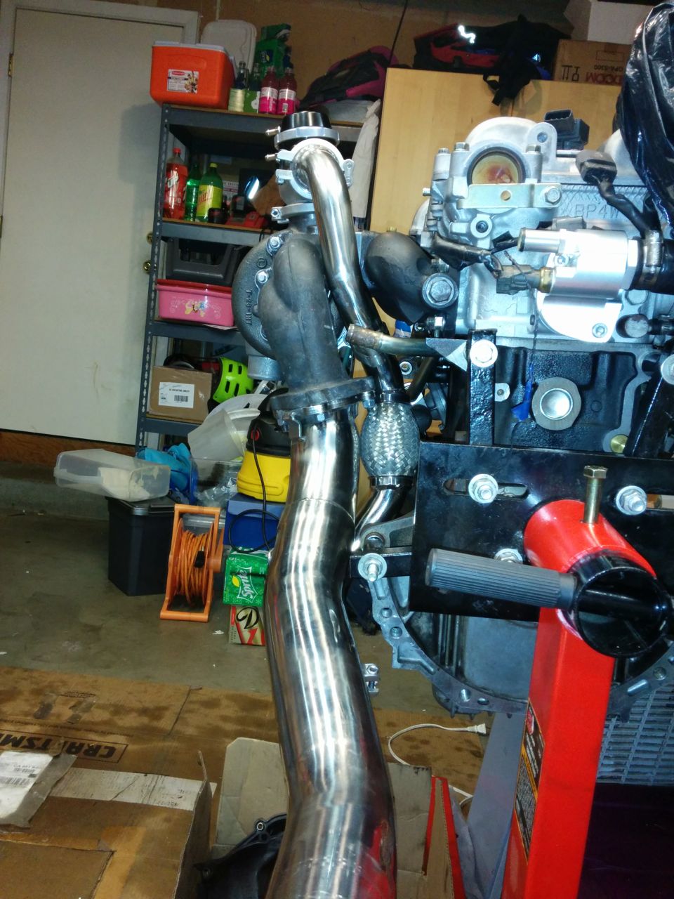
Then, with much wiggling and cursing and swearing and whatnot, the tranny went on the engine.
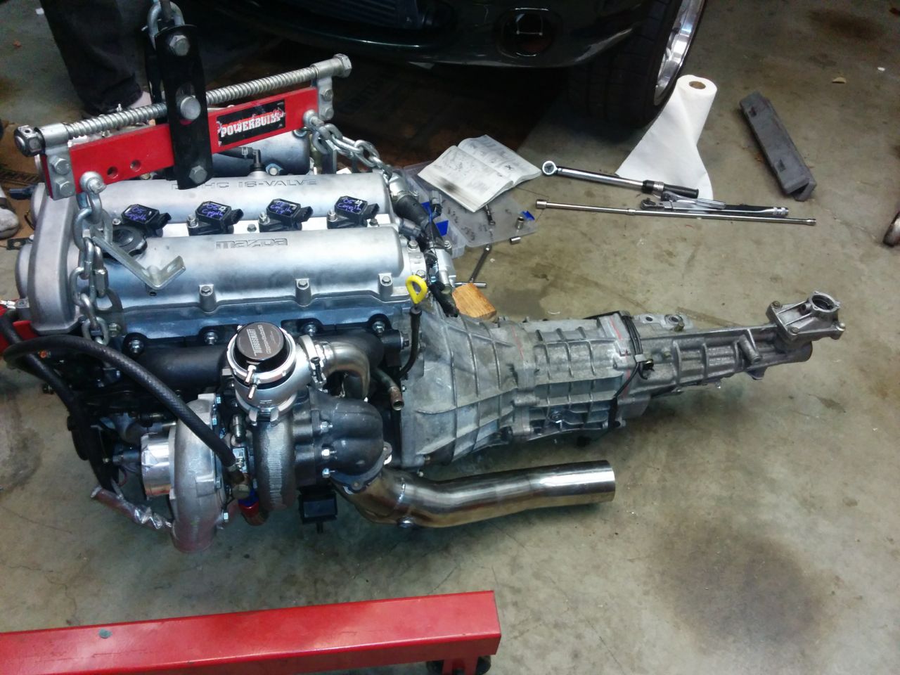
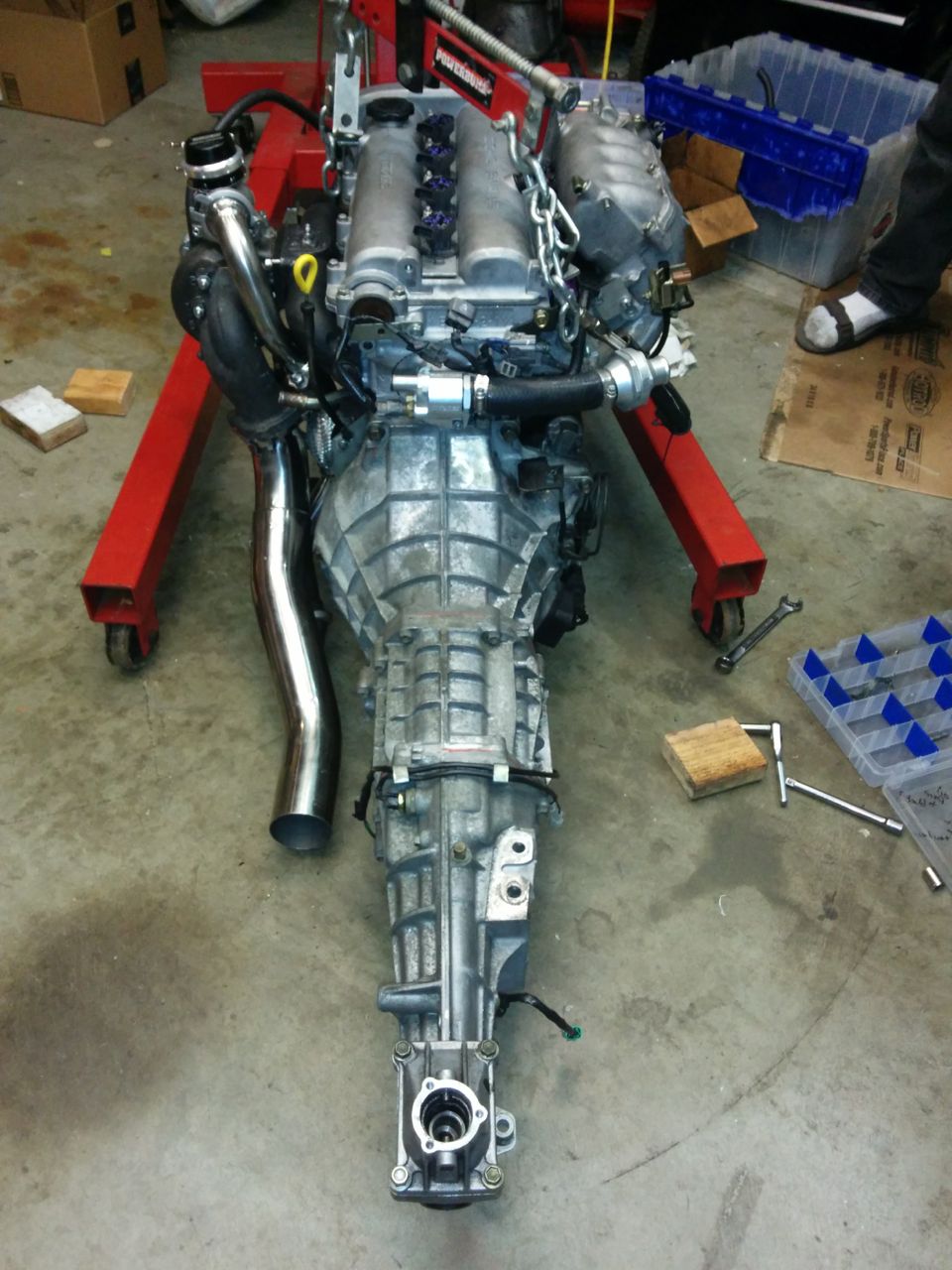
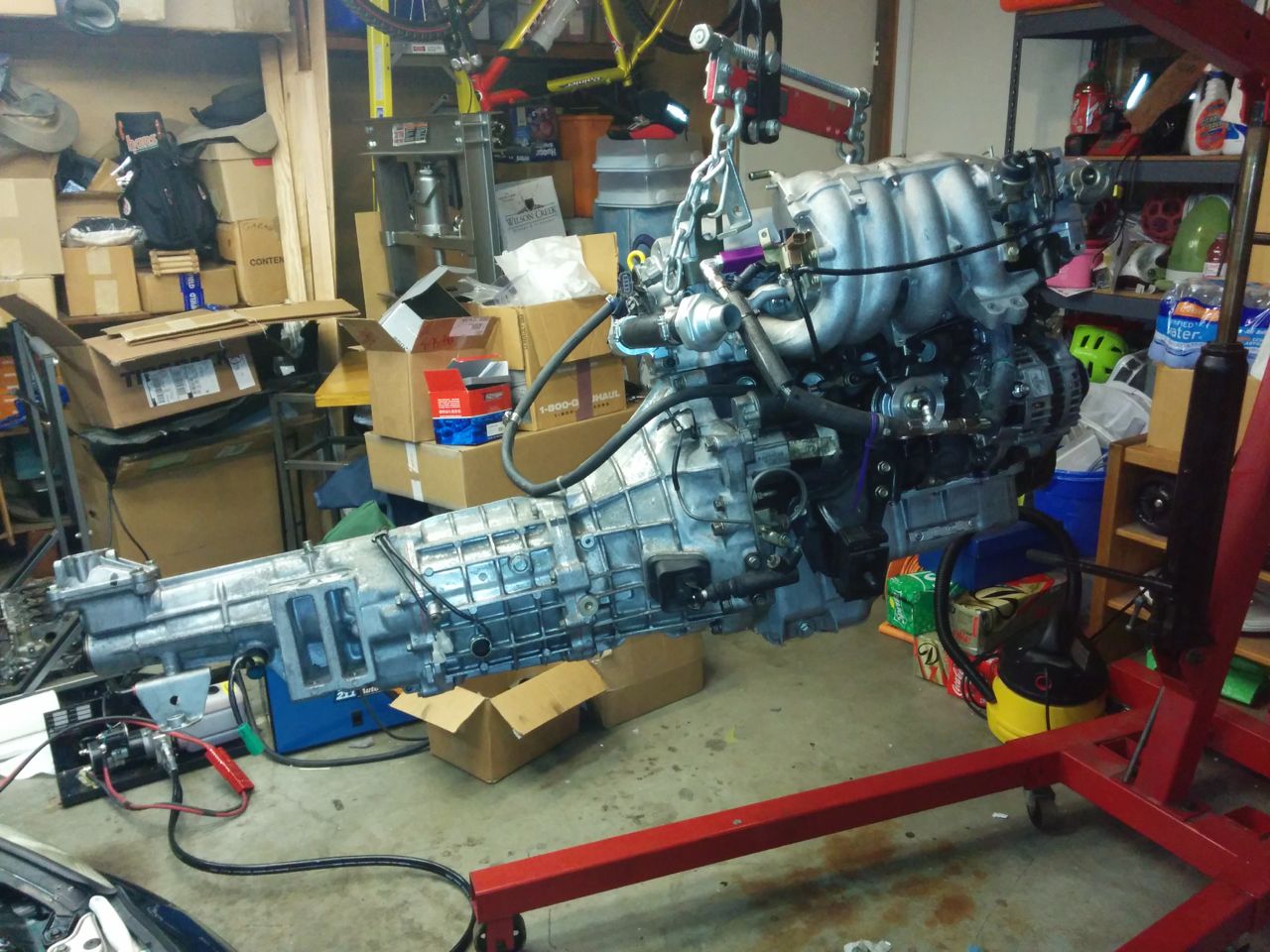
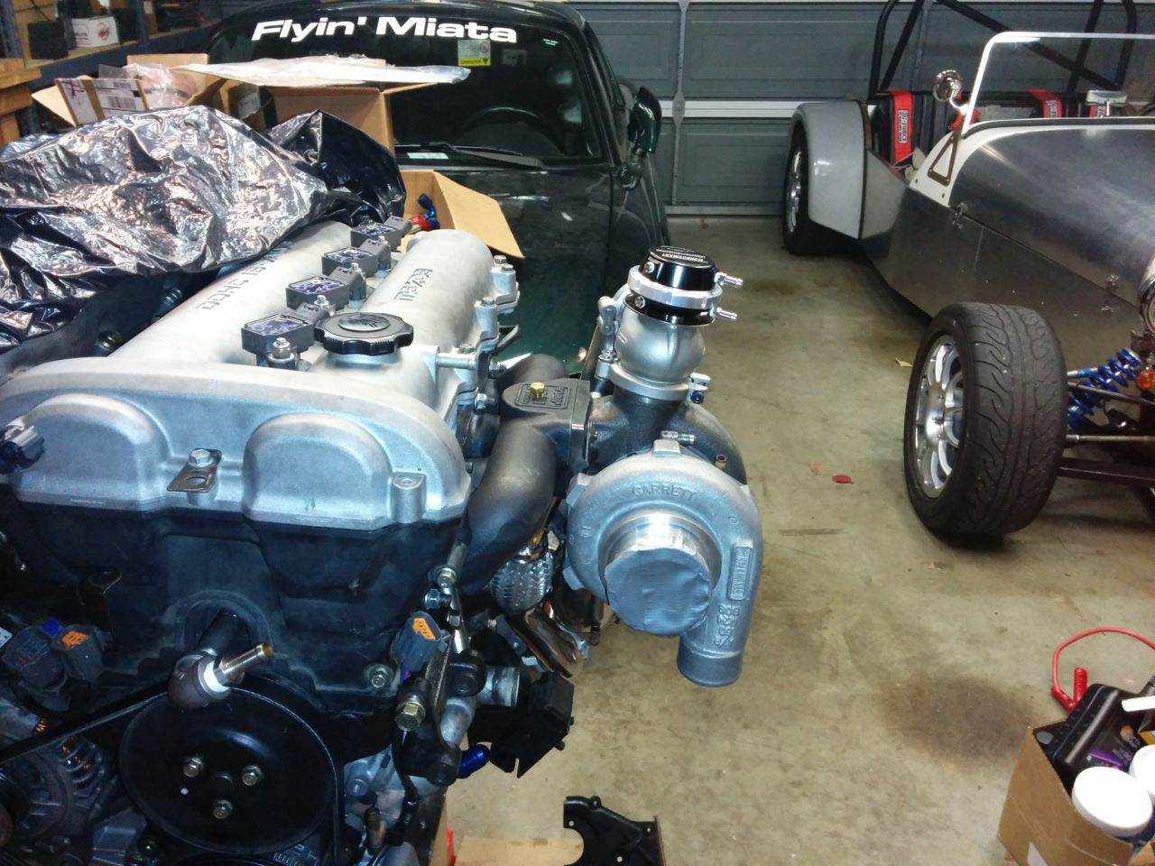
And then it was time to put it in:
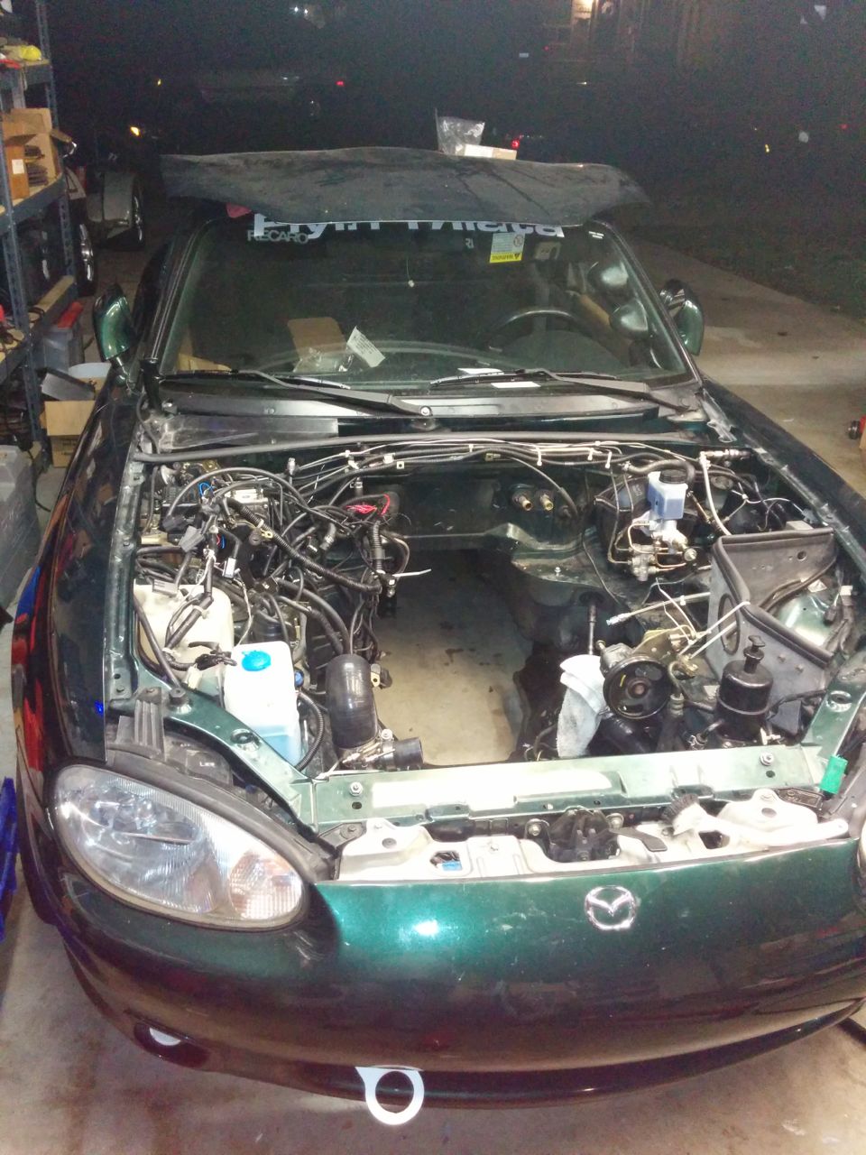
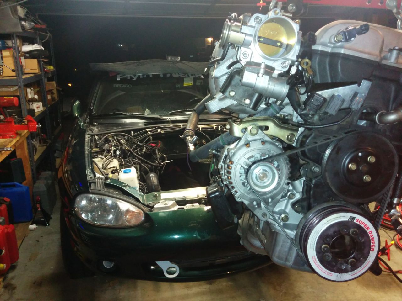
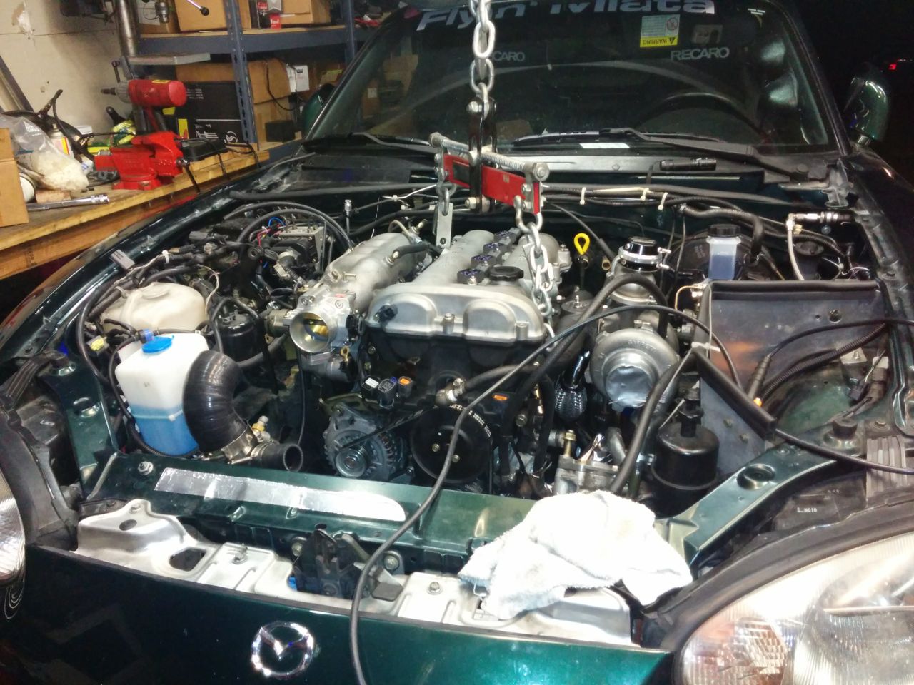
And after more cursing and pushing and swearing, it was in!!!
Unfortunately, it probably has to come out again.
I had previously clearanced the shelf for the old 2560 -- well, the 2863 is a bit bigger. The compressor is about the same size, but it curves "up" a bit at the end of the outlet, and so the clearancing needs to be a half-inch or so longer. The turbine is significantly bigger than the 2560, and while it *does* fit in the car right now, there's not much room between it and the shelf and I'm afraid it's going to hit when the motor rocks around under torque. Since I'm hoping for a lot of that, the shelf needs trimming, which means the motor has to come back out. Argh.
--Ian
And then it was time to put it in:
And after more cursing and pushing and swearing, it was in!!!
Unfortunately, it probably has to come out again.
I had previously clearanced the shelf for the old 2560 -- well, the 2863 is a bit bigger. The compressor is about the same size, but it curves "up" a bit at the end of the outlet, and so the clearancing needs to be a half-inch or so longer. The turbine is significantly bigger than the 2560, and while it *does* fit in the car right now, there's not much room between it and the shelf and I'm afraid it's going to hit when the motor rocks around under torque. Since I'm hoping for a lot of that, the shelf needs trimming, which means the motor has to come back out. Argh.
--Ian
Reply
0
0
12-22-2014, 08:32 AM
#80
Moderator

iTrader: (12)
Join Date: Nov 2008
Location: Tampa, Florida
Posts: 20,645
Total Cats: 3,008
I had to clock my compressor outlet up at a 2 o'clock position to clear with the FM manifold and I still had to hammer the pinch weld down flat against the frame rail.
My FM cast mani had been relief cut by the previous owner. I still had to cut it two more times since then because it continues to close up over time. I also had it resurfaced (of course) because I knew the casting was gradually changing shape over time. It happens until it reaches its point of relaxation and stasis, I guess.
My FM cast mani had been relief cut by the previous owner. I still had to cut it two more times since then because it continues to close up over time. I also had it resurfaced (of course) because I knew the casting was gradually changing shape over time. It happens until it reaches its point of relaxation and stasis, I guess.
Reply
0
0


