Lazarus:making something out of nothing


 12-06-2015, 11:08 AM
#505
Senior Member
Thread Starter
iTrader: (3)

Join Date: Nov 2011
Location: Beaverton, OR
Posts: 771
Total Cats: 39
The dash is retained with some trimming, it attaches to the stock bolt that sits near the middle of the windshield and then 2 plates that are attached to the cage on either side.

Reply
 0
0

0


 12-31-2015, 12:30 PM
#508
Senior Member
Thread Starter
iTrader: (3)
Join Date: Nov 2011
Location: Beaverton, OR
Posts: 771
Total Cats: 39
Copied from CR
Martin wants an update while he's in Hawaii, so here y'all go!
Original plan was just to dyno it with a few changes, but a lot of these projects are connected. The dash came out after his half cage was turned into a full cage, and although it was meant to go back in, it was in a poor state and was never going to look good again. So we decided to go full race car and remove the dash completely. This also lets us fix a lot of ugly wiring which has all been added at seperate times, like sequential injection, EBC, VICS, and gauge wiring. It was a rats nest of a million wires with 3 million crimps that I cut out and will be redoing properly with the new gauge panel.
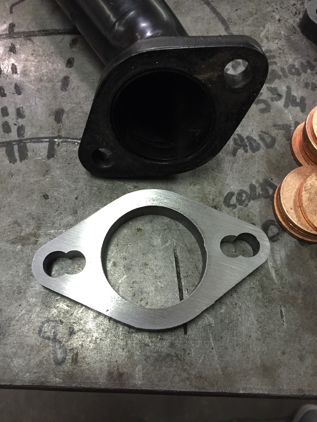
Today and yesterday I spent a few hours with Kris at KO Racing to help with a lot of the fab work on Laz's intercooler pipes. Spent an hour doing trig to make his Tial wastegate flange have MSM compressor outlet hole spacing. Why an hour? Because CNC.
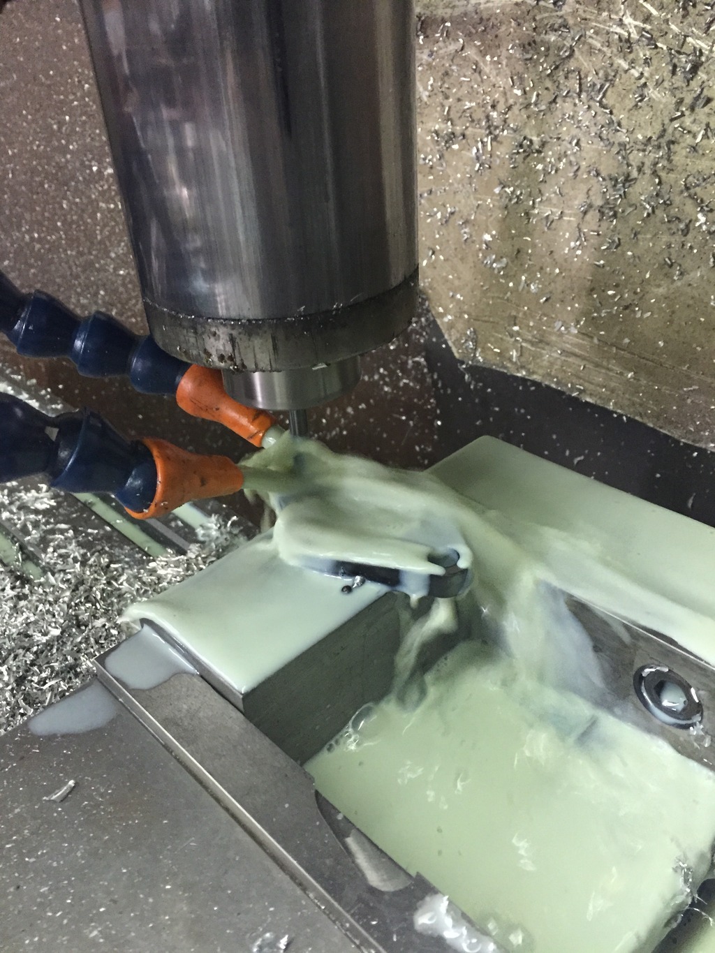
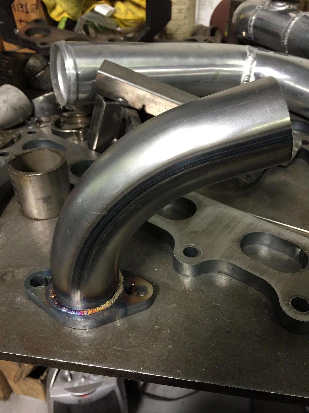
Turned it into this:
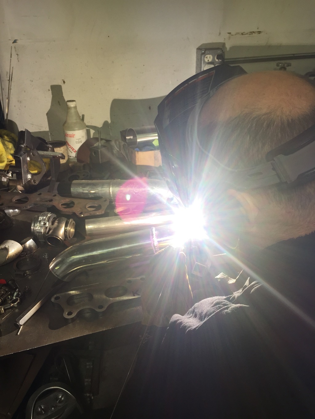
He also did some TIG welding.
And some bead rolling.
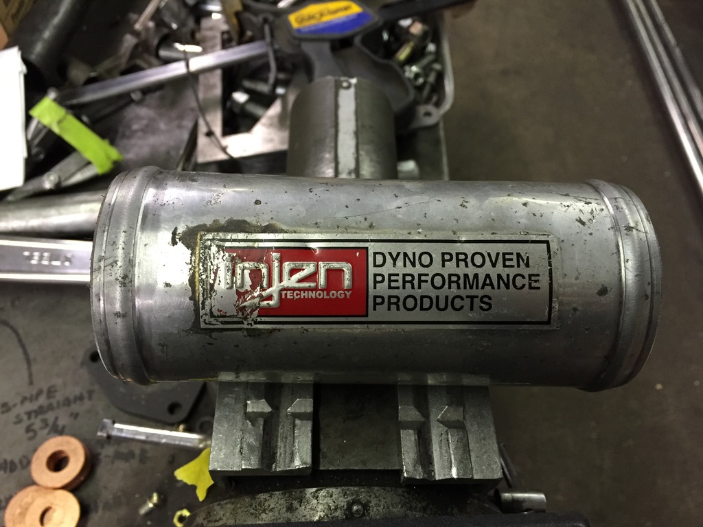
These pieces completed the cold side intercooler pipe. Fully beaded with only 3 couplers.
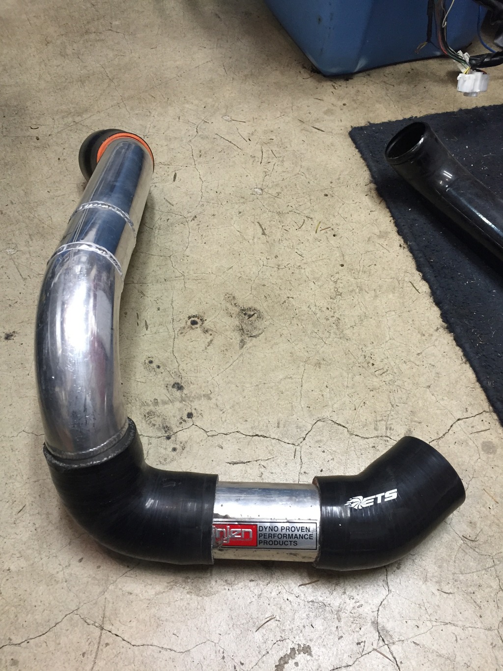
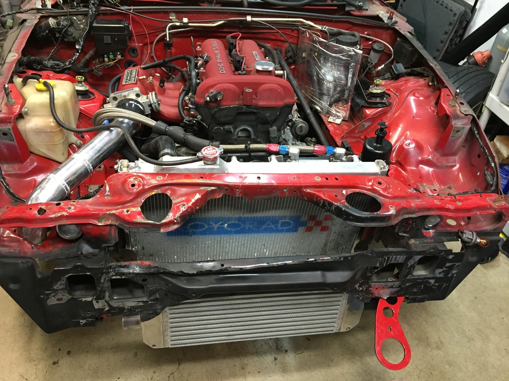
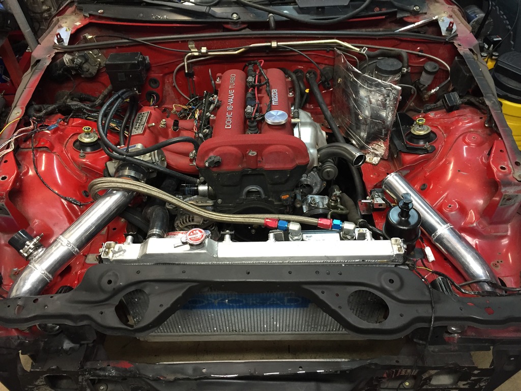
And here it is installed, along with the Honda intake manifold, Fab9 intercooler, and new tow hook.
Here's my plan for the hot side. This is technically the cold side piping from the previous picture, but I should be able to mirror it on the hot side, including only having 3 couplers and it'll be fully bead rolled. I just need to get that funky compressor outlet pipe fabricated and expanded to 2.5" from 1.5".
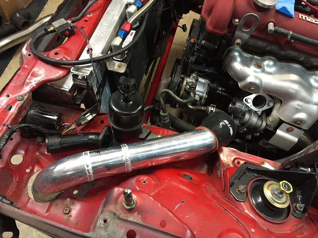
Also pictured, power steering. He now has Mobius' rack from his wrecked '01, which also cuts about 4.5 feet off his turning radius.
We're also getting rid of the dash, and replacing it with something like this, courtesy of Humming Aero:
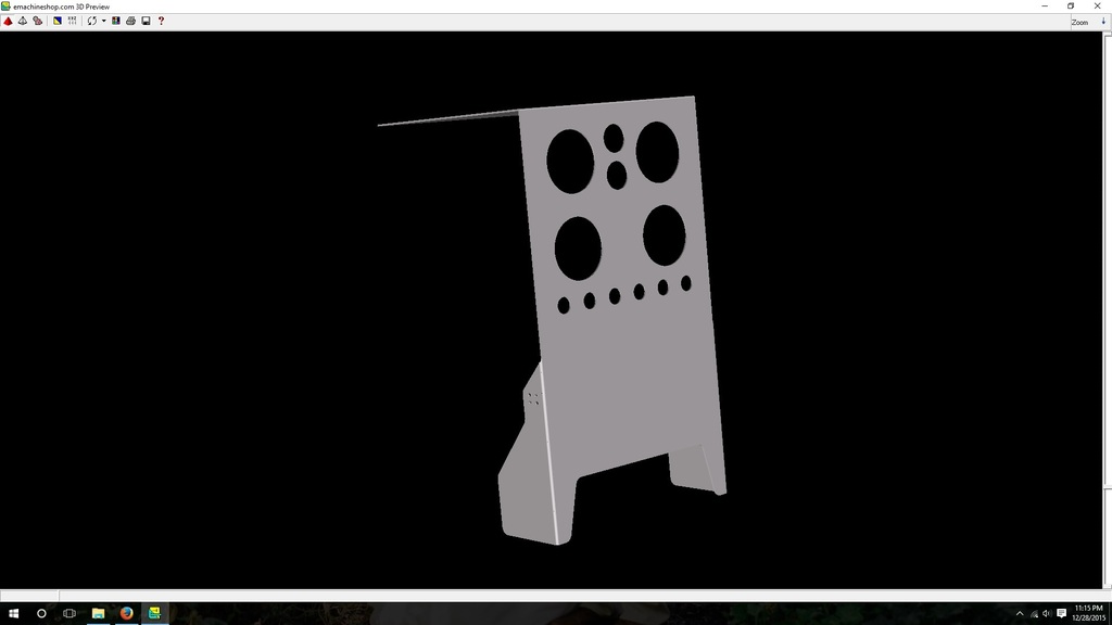
Gauges are AFR, oil temp, boost, and water temp. Switches are WTFK.
On it's way:
1. NB PS pump for complete tensioner hardware
2. Oil temp sensor for sandwich plate
Need to buy:
1. Couplers for intercooler setup
2. gauge panel
Need to fab:
1. compressor outlet
2. hot side intercooler pipe
3. ducting
4. gauge panel
5. stock gauge cluster mounts
Need to install:
1. Inner tie rods and boots
2. Front wheels
3. oil temp sensor
4. intake manifold
5. cold side piping
6. hot side piping
7. gauge panel
Need to wire:
1. Everything
Original plan was just to dyno it with a few changes, but a lot of these projects are connected. The dash came out after his half cage was turned into a full cage, and although it was meant to go back in, it was in a poor state and was never going to look good again. So we decided to go full race car and remove the dash completely. This also lets us fix a lot of ugly wiring which has all been added at seperate times, like sequential injection, EBC, VICS, and gauge wiring. It was a rats nest of a million wires with 3 million crimps that I cut out and will be redoing properly with the new gauge panel.
Today and yesterday I spent a few hours with Kris at KO Racing to help with a lot of the fab work on Laz's intercooler pipes. Spent an hour doing trig to make his Tial wastegate flange have MSM compressor outlet hole spacing. Why an hour? Because CNC.

Turned it into this:

He also did some TIG welding.

And some bead rolling.

These pieces completed the cold side intercooler pipe. Fully beaded with only 3 couplers.

And here it is installed, along with the Honda intake manifold, Fab9 intercooler, and new tow hook.

Here's my plan for the hot side. This is technically the cold side piping from the previous picture, but I should be able to mirror it on the hot side, including only having 3 couplers and it'll be fully bead rolled. I just need to get that funky compressor outlet pipe fabricated and expanded to 2.5" from 1.5".

Also pictured, power steering. He now has Mobius' rack from his wrecked '01, which also cuts about 4.5 feet off his turning radius.
We're also getting rid of the dash, and replacing it with something like this, courtesy of Humming Aero:

Gauges are AFR, oil temp, boost, and water temp. Switches are WTFK.
On it's way:
1. NB PS pump for complete tensioner hardware
2. Oil temp sensor for sandwich plate
Need to buy:
1. Couplers for intercooler setup
2. gauge panel
Need to fab:
1. compressor outlet
2. hot side intercooler pipe
3. ducting
4. gauge panel
5. stock gauge cluster mounts
Need to install:
1. Inner tie rods and boots
2. Front wheels
3. oil temp sensor
4. intake manifold
5. cold side piping
6. hot side piping
7. gauge panel
Need to wire:
1. Everything
Reply
0
0
12-31-2015, 12:50 PM
#510
SADFab Destructive Testing Engineer


iTrader: (5)
Join Date: Apr 2014
Location: Beaverton, USA
Posts: 18,642
Total Cats: 1,866
Don't know if you have any plans to log oil temp with the megasquirt, but there is a Saturn temp sensor that uses the GM curve and can be wired into the megasquirt pretty easily.
I have a bunch of pigtails from the junkyard for it too.
I have a bunch of pigtails from the junkyard for it too.
Reply
0
0
 12-31-2015, 05:37 PM
#512
SADFab Destructive Testing Engineer
iTrader: (5)
Join Date: Apr 2014
Location: Beaverton, USA
Posts: 18,642
Total Cats: 1,866
Reply
0
0
01-03-2016, 02:43 PM
#513
Senior Member
Thread Starter
iTrader: (3)
Join Date: Nov 2011
Location: Beaverton, OR
Posts: 771
Total Cats: 39
More updates
Ok intercooler pipes are finally finished. Hardest part was getting the correct angle and orientation on the new compressor outlet, but it's finished. I upped it by .25" from 1.5" to 1.75", because most couplers don't reduce smaller than 1.75", at least the ones at siliconeintakes.com don't.
The entire hot side was nearly all guess work, the cold side elbow looked usable, so I had Kris at KO Racing copy it. I can't recommend him enough for any of your fabrication needs. I'd love to do this myself, but I'd rather spend $350 getting this done instead of $3500 of tools. For now.
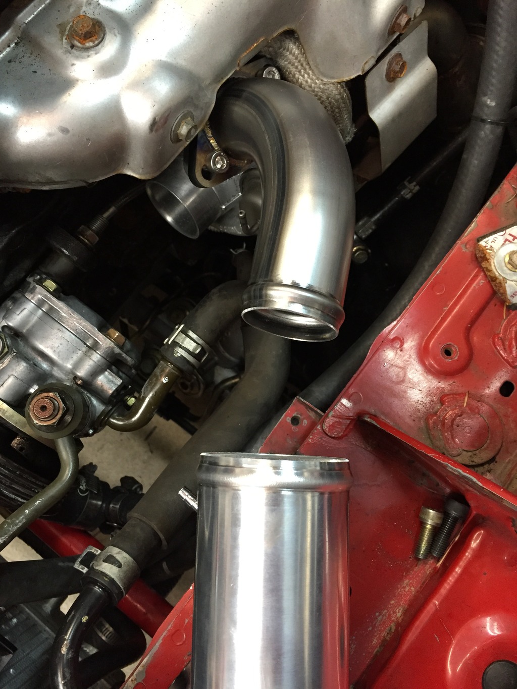
The compressor outlet is the only steel piece in the intercooler setup, Ideally it'd be powder coated I think, but we ain't got time for that, so high temp paint for now.
Here's the "completed" setup, just missing the couplers. When it's sitting in it's proper place, the hot side aluminum pipe is ~2" from the compressor outlet. Kris says he shoots for 1" between pipes, but again this was all remotely fabricated. The reducer coupler on siliconeintakes is only 3", which doesn't leave much on the pipe, so I'll probably have to bring it back for one more extension.
Next up is wiring, I've been finishing up the engine bay, routing everything I need into the cockpit to eventually bolt up to the gauge panel. I'm attempting to integrate everything into the dash harness, we'll see how that goes!
The entire hot side was nearly all guess work, the cold side elbow looked usable, so I had Kris at KO Racing copy it. I can't recommend him enough for any of your fabrication needs. I'd love to do this myself, but I'd rather spend $350 getting this done instead of $3500 of tools. For now.
The compressor outlet is the only steel piece in the intercooler setup, Ideally it'd be powder coated I think, but we ain't got time for that, so high temp paint for now.

Here's the "completed" setup, just missing the couplers. When it's sitting in it's proper place, the hot side aluminum pipe is ~2" from the compressor outlet. Kris says he shoots for 1" between pipes, but again this was all remotely fabricated. The reducer coupler on siliconeintakes is only 3", which doesn't leave much on the pipe, so I'll probably have to bring it back for one more extension.


Next up is wiring, I've been finishing up the engine bay, routing everything I need into the cockpit to eventually bolt up to the gauge panel. I'm attempting to integrate everything into the dash harness, we'll see how that goes!
Reply
0
0
 02-28-2016, 01:16 PM
#519
Cpt. Slow
iTrader: (25)
Join Date: Oct 2005
Location: Oregon City, OR
Posts: 14,179
Total Cats: 1,129
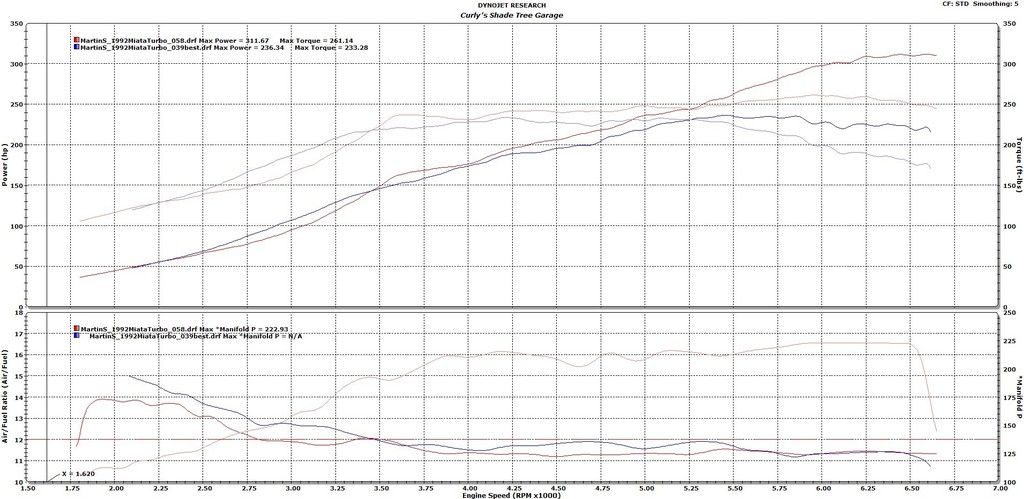
This graph was the hilarious one:
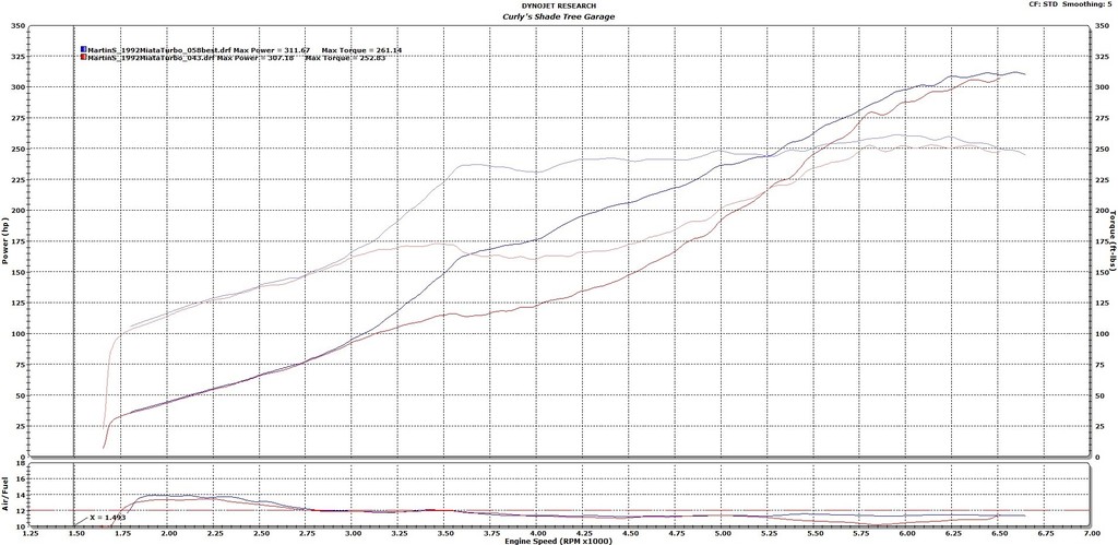
This is a before/after of this particular dyno session. Came in with 122hp at 4000rpm and 310 by 6500. Boost control was shut off to try and work our way up to high boost, but it was obvious the new compressor wheel was over powering the wastegate hole. Fail. So we made boost 225kpa throughout the entire power band. Worked well!

This is a before/after of this particular dyno session. Came in with 122hp at 4000rpm and 310 by 6500. Boost control was shut off to try and work our way up to high boost, but it was obvious the new compressor wheel was over powering the wastegate hole. Fail. So we made boost 225kpa throughout the entire power band. Worked well!
Reply
0
0
02-28-2016, 01:25 PM
#520
Cpt. Slow
iTrader: (25)
Join Date: Oct 2005
Location: Oregon City, OR
Posts: 14,179
Total Cats: 1,129
Oh and the 236/233 graph martin posted was:
VICS manifold, stock throttle body, shitty leaky intercooler pipes made up of OEM mitsubishi stuff, stock turbo, and an OEM evo 8(??) intercooler, again hacked up to fit.
Laz is now: Honda manifold, S2 72mm(?) throttle body, Fab9 baby intercooler, some Subaru billet compressor wheel with a rebuilt turbo, and KO Racing fabb'ed 2.5" intercooler pipes.
Reply
0
0


