Flowbench Build
 03-08-2009, 03:00 AM
#1
Junior Member
Thread Starter
iTrader: (4)

Join Date: Sep 2006
Location: Bakersfield, Ca
Posts: 154
Total Cats: 0
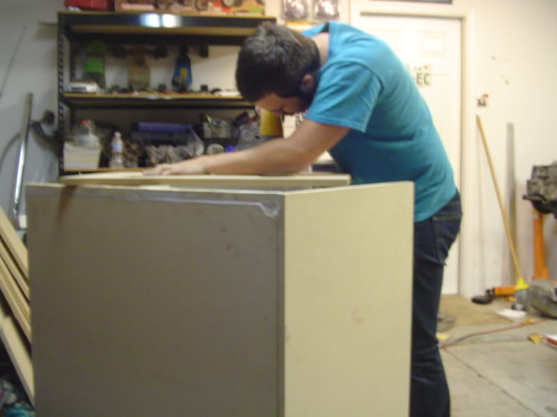
Well I have been working over cylinder heads for quite a long time and was tired of being held back because I lacked the tooling to measure airflow (quality as well as quantity). I wanted to have the ability to manipulate airflow and also have the ability to measure and record data for further testing . So I decided to build a flow bench for my hobby shop. It will be capable of 450cfm-460cfm @ 28" (Capacity can be increased with addition of motors, but it should be sufficient for the time being). Current orifice plate is capable of 335cfm. It is measured with a Digital manometer that consists of three pressure pick ups: One for static pressure (For my Velocity probe), Second static pressure pick up and a differential pressure pick up to make calculations more simplistic.
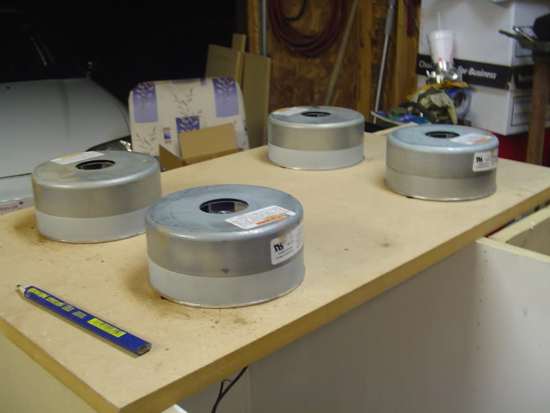
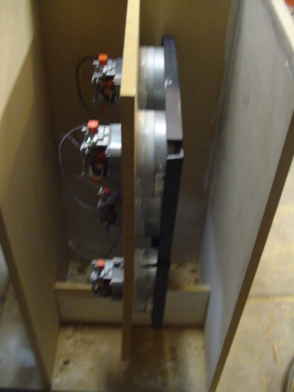
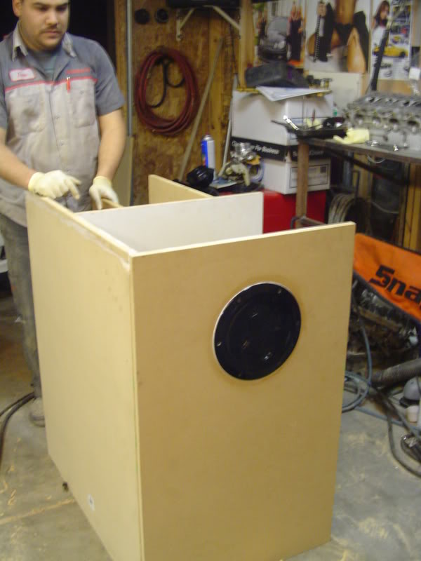
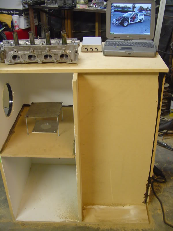
Me and my buddy have constructed the outer portion of the bench so far. We have added an access plate and sealed all joints. We also mounted the motors and made a sandwich plate for added security. All that is remaining is the wiring, construction of the head adapter plates, valve opening tool and slider plate. I am currently having plexiglass cylinders machined in various sizes (within a .020" tolerance) so I can accurately simulate an engine's bore size. It's sure is a huge PITA. When finished it will have taken 50-60 hours and more money than I care to count but it will be worth it. I will also be able to test a ton of cylinder heads! This Bench should, if all goes to plan, be finished by next weekend. I have a bunch of heads to work over and flow test. So I have to get a move on!
Here are some pictures of the work in progress. Sorry if they are a bit blurry. I will blame it on the lighting.
Last edited by leshok; 03-08-2009 at 03:31 AM.

Reply
 0
0

0


 03-08-2009, 01:40 PM
#9
Junior Member
Thread Starter
iTrader: (4)
Join Date: Sep 2006
Location: Bakersfield, Ca
Posts: 154
Total Cats: 0
Thanks for the nice words guys!
Yes I will be able to flow both.
Yes I am using plans from a functional bench. It consist of 2 plenum chambers that record static and differential pressures. In my case I added another static pick up for my velocity probe. The orifice plate is then used to calculate airflow in cfm.
Yes I am using plans from a functional bench. It consist of 2 plenum chambers that record static and differential pressures. In my case I added another static pick up for my velocity probe. The orifice plate is then used to calculate airflow in cfm.
Reply
0
0

 03-08-2009, 03:03 PM
#11
Junior Member
Thread Starter
iTrader: (4)
Join Date: Sep 2006
Location: Bakersfield, Ca
Posts: 154
Total Cats: 0
I would have no problem doing that. Since I am "new" to the miata community. I could offer cylinder heads for a reduced. Something like..
-Disassembled
-Inspected
-Clearances measured (Valve guide to Stem, Cam Journal to Cam bores,..ect)
-Glass Beaded
-Crack Checked
-Resurface or Angle Milled parallel to camshaft bores (depends on application)
-Valve job (Different angles used for different customers: Based on valve type, Camshaft Characteristics, and anti-reversion potential
-Ports reworked for velocity and optimum flow (Application Specific). Anti-reversion steps come with every head done
-Chambers reworked for efficient combustion
-Combustion chambers CC'ed
-Intake Ports flowed forwards and backwards for anti-reversion potential
-Exhaust Ports flow tested
-Flow Charts Printed out
-Head Reassembled
This is obviously a top of the line head. This particular set up will run about $575-$600. This is only because I will have to spend about 20-25 hours on each head.
But I think I will have stages 1-3 that will range from $375 to $600.
Does that sound like a good deal guys?
P.S. I think I will be doing manifold porting for the miata intake manifolds. I could cut the plenum and shape the entrance of the runners. I can also test manifolds bolted to the head.
Reply
0
0
03-11-2009, 03:11 PM
#14
Junior Member
Thread Starter
iTrader: (4)
Join Date: Sep 2006
Location: Bakersfield, Ca
Posts: 154
Total Cats: 0
More updates. I just received the orifice plate and digital manometer today. I also got the relays and motor controls ordered.
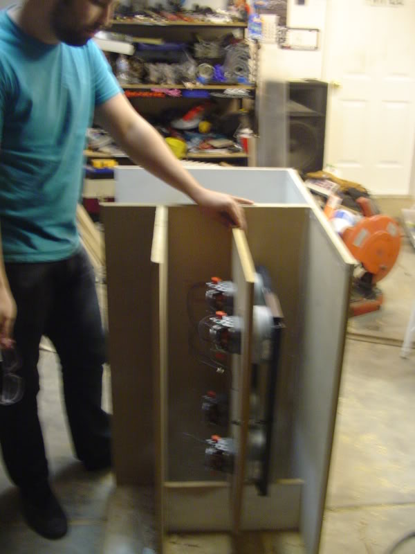
Today we made the remaining pieces of the slider and selector plates. We also got the motors mounted and just before we left, mocked up how it will look once everything is completed. Now I just need to make my valve opening fixture and wiring the thing! Here are some pictures of the progress.
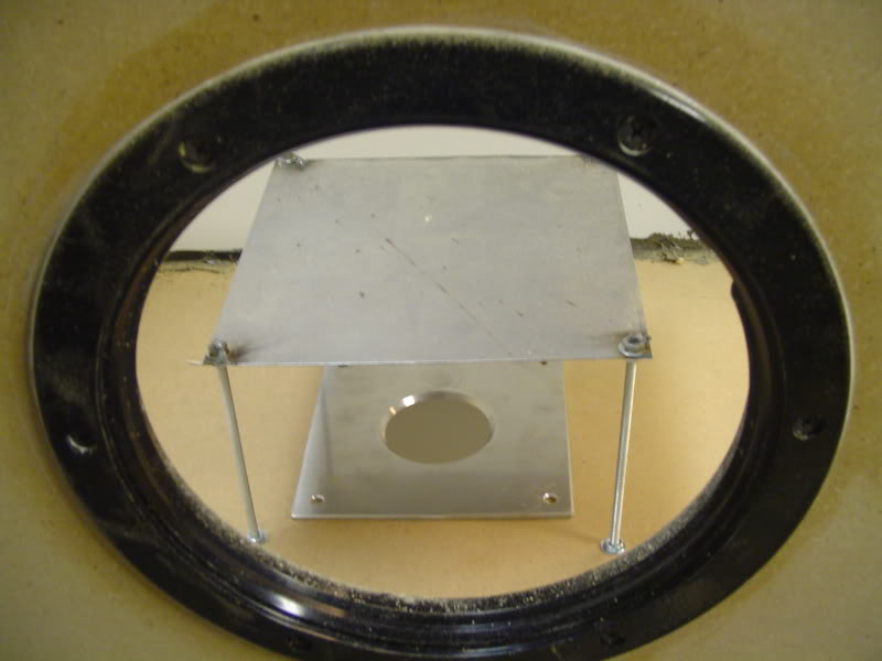
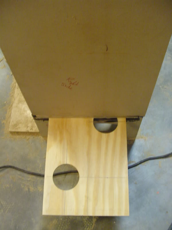
Today we made the remaining pieces of the slider and selector plates. We also got the motors mounted and just before we left, mocked up how it will look once everything is completed. Now I just need to make my valve opening fixture and wiring the thing! Here are some pictures of the progress.
Reply
0
0


 03-11-2009, 08:17 PM
#18
Elite Member
iTrader: (11)

Join Date: Jun 2007
Location: Overland Park, Kansas
Posts: 5,360
Total Cats: 43
Really impressive.
I've wanted to build one of these for personal toying over the years, but keep hearing they're way far off. Id be anxious to see you flow a head then have a benchmark check your numbers.
Either way, I think honestly even if it wasn't dead on accurate, it should at least give you an idea if you're going in the right direction.
Reply
0
0
03-11-2009, 08:21 PM
#19
Junior Member
Thread Starter
iTrader: (4)
Join Date: Sep 2006
Location: Bakersfield, Ca
Posts: 154
Total Cats: 0
All benches..even superflow's have a 1-2% margin of error. It is kind of like a dyno..good tool to measure increases or decreases. The original number is arbitrary. It terms of the "industry standard" I think it will fit right in.
Reply
0
0
03-23-2009, 04:26 AM
#20
Junior Member
Thread Starter
iTrader: (4)
Join Date: Sep 2006
Location: Bakersfield, Ca
Posts: 154
Total Cats: 0
Update: We got the bench all wired up (what a pain!), and performed a smoke check. Needless to say it came out perfectly! Now I just got to seal the entire thing up, and make sure there are zero air leaks. I also got to set up the computer program and calibrate the bench. Then I will be able to run the first experiments.
First experiment with be a mangnaflow cat vs oem cat..something along those lines.
First experiment with be a mangnaflow cat vs oem cat..something along those lines.
Reply
0
0


