Se7en Turbo Build (Was: Thermostat Rerouting)
 01-25-2010, 02:02 AM
#1
Junior Member
Thread Starter

Join Date: Oct 2008
Location: Cortland, Ohio
Posts: 113
Total Cats: 5
I have read most posts, surfed through quite a few forums, and looked at the main conversion kits, however, none have applied to my specifications.
I am building a Locost, or a Lotus 7-based car. I've gotten it put together anough to drive it, basically all that's left is to finish the bodywork and tuck some of the wiring.
I've gone through the entire harness, trimming it from over 120 wires at one point, to around 35-40, and shortened it by 5 feet. I deleted the lighting from the harness and ended up making my own.
I removed the heating and cooling, looping the heating hose back to the water pump housing/whatever you call that part.
I started out with a 94 motor, and I found out why it was in the junkyard to begin with--a seized ring in cylinder 3. so at that point, I bought a 96 motor and reverted it back to OBDI, and that's what's in the Seven now.
I intend on eventually boring the 94 block out, replacing the internals and going for a low compression/high boost setup. For now, though, I am working on mating a Super 16G wth the 96 motor, with an aim of 6-8 psi. The biggest problem I am having is location. Within the tight confinements of the Seven engine bay, a conventional turbo located at the end of a short turbo manifold is out, as the steering and brake components are in the way. I intend on locating the turbo n front of the engine, about level with the thermostat housing. Thus, the dilemma: the thermostat housing has to go.
So I have a basic/primitive understanding of the miata drivetrain, howeveran im having a hard time understading the thermostat reroute.
At least on the 94 BP05, the thermostat and thermostat housing fit perfectly on the rear housing. Why can't I put a block-off plate on the front, bolt the thermostat and housing, and tap a bung for the ecu temperature sensor? With the heating core removed, is there an actual reason to have a line going from the upper to the lower radiator lines?
Note: I don't know all the correct terminology of some hoses and partsan so diagrams are generally better if going into detail.
Nate/SteyrTMP

Reply
 0
0

0
01-25-2010, 02:13 AM
#2
Boost Pope


iTrader: (8)
Join Date: Sep 2005
Location: Chicago. (The less-murder part.)
Posts: 33,015
Total Cats: 6,587
The primary reason most of us do this is that it vastly improves the even-ness of the engine's operating temperature (front to back) and improves overall cooling efficiency.
With the heating core removed, is there an actual reason to have a line going from the upper to the lower radiator lines?
Reply
0
0
01-25-2010, 08:31 AM
#3

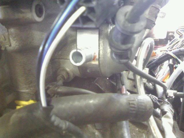
I've got a 96 as well. I drilled and tapped the head for my heater hose fitting and used an existing plugged port for my ECU sensor. Note the sensor will interfere with the waterneck unless you modify it. I just cut off my plastic plug and bent the leads 90 degrees like this:

Here it is installed:

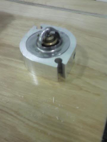
You will need some sort of spacer if you want to go around the cold side to get over the water boss that's there. I used a $15 spacer from Moss and a Kia waterneck.
Final product:

Here it is installed:
You will need some sort of spacer if you want to go around the cold side to get over the water boss that's there. I used a $15 spacer from Moss and a Kia waterneck.
Final product:
Reply
0
0
01-25-2010, 08:41 AM
#4
Boost Czar

iTrader: (62)
Join Date: May 2005
Location: Chantilly, VA
Posts: 79,483
Total Cats: 4,076
That is essentially what many of us do to our own engines. Remove the front thermostat housing and block it off. At the back, remove the water outlet. We typically install a spacer there, then the thermostat, and then the thermostat cover. (The spacer gives you a place to mount the temp sensor as well as take the feed for the heater core, from before the thermostat. Some people drill and tap the head itself for this instead.)
The primary reason most of us do this is that it vastly improves the even-ness of the engine's operating temperature (front to back) and improves overall cooling efficiency.
You need to have a path for coolant to circulate through the engine when the thermostat is closed. In the standard design, the heater core provides this function, by taking water from before the thermostat and returning it to the water pump inlet (at what we call the mixing manifold) which is also where the lower radiator hose connects.
Reply
0
0
01-25-2010, 02:01 PM
#5
Junior Member
Thread Starter
Join Date: Oct 2008
Location: Cortland, Ohio
Posts: 113
Total Cats: 5
Ok. That makes sense. After some more searching, I found Frank Devoucht's site, which REALLY helped.
http://users.telenet.be/miata/englis...nt_reroute.htm
However, I can't find two parts: the 323 dual-outlet water boss, and the spacer, as it appears Moss no longer carries it.
Any ideas there?
http://users.telenet.be/miata/englis...nt_reroute.htm
However, I can't find two parts: the 323 dual-outlet water boss, and the spacer, as it appears Moss no longer carries it.
Any ideas there?
Reply
0
0
 01-25-2010, 02:50 PM
#7
Use the Kia waterneck if you dont want to worry about plugging the 1.6 outlet. I got mine from a junkyard for $8 or so.
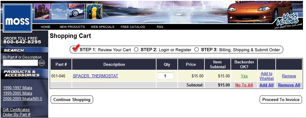
To order the spacer from Moss, follow the instructions on the page you just linked or here it is in 4 easy steps.
1. Go to this page
2. Type in this number "051-046"
3. Hit Submit button.
4. Go pay
To order the spacer from Moss, follow the instructions on the page you just linked or here it is in 4 easy steps.
1. Go to this page
2. Type in this number "051-046"
3. Hit Submit button.
4. Go pay
Reply
0
0
01-25-2010, 02:50 PM
#8
Hey Nate, welcome to the forum! We have a couple of Locosters here. I'm not very active over there any more since I sold mine to Winston (who sold it to Titus) but I still check in now and then.
Post up an intro thread with a couple of Locost progress pics in the Meet and Greet section. Normally the guys are pretty tough on noobs. People have been pretty nice to you because you A: are a DIY'er and they respect that and B: it's obvious that you have done your research before asking your question. This forum is run a bit "looser" than Locost USA.
That said, we all like to see pics!
Reply
0
0
01-26-2010, 12:24 AM
#9
Junior Member
Thread Starter
Join Date: Oct 2008
Location: Cortland, Ohio
Posts: 113
Total Cats: 5
Huh. I wasn't able to get that earlier. probably because a) that's the first time I've seen an online store with that feature, and b) I am doing all this on my phone (an sch-i760), and its finiky about what pages show up. I will order one.
Would the spacer be a good place to tap in for the turbo coolant line?
Stein, I remember you from LocostUSA. I will have to post an intro once I get the main pc online again
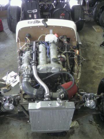
These pictures aren't that great--I was focusing more on my buddy's frame ( I am helping him build a 4g63-powered locost, a first as far as we know). Thus, I have been spending most of my time working on his car rather than mine.
Now that I found out how to reroute the thermostat , I can get back to my car. I am about to buy intake and exhaust flanges for the 16g6 so I can start on the turbo exhaust--both engine-side and for the turbo itself, as the factory cast turbine exhaust flage is pointing in the wrong way afteri rotate the housing.
Here's hoping that MegaSquirt III comes out in full production soon!
http://i39.photobucket.com/albums/e1...210090922a.jpg
http://i39.photobucket.com/albums/e1...1207091339.jpg
Would the spacer be a good place to tap in for the turbo coolant line?
Stein, I remember you from LocostUSA. I will have to post an intro once I get the main pc online again
These pictures aren't that great--I was focusing more on my buddy's frame ( I am helping him build a 4g63-powered locost, a first as far as we know). Thus, I have been spending most of my time working on his car rather than mine.
Now that I found out how to reroute the thermostat , I can get back to my car. I am about to buy intake and exhaust flanges for the 16g6 so I can start on the turbo exhaust--both engine-side and for the turbo itself, as the factory cast turbine exhaust flage is pointing in the wrong way afteri rotate the housing.
Here's hoping that MegaSquirt III comes out in full production soon!
http://i39.photobucket.com/albums/e1...210090922a.jpg
http://i39.photobucket.com/albums/e1...1207091339.jpg
Reply
0
0
01-26-2010, 02:46 AM
#10
Boost Pope
iTrader: (8)
Join Date: Sep 2005
Location: Chicago. (The less-murder part.)
Posts: 33,015
Total Cats: 6,587
Take the coolant from the front of the engine where you removed the thermostat, or from the threaded outlet on the exhaust side of the block near the flywheel.
Reply
0
0
01-26-2010, 03:02 AM
#11
Junior Member
Thread Starter
Join Date: Oct 2008
Location: Cortland, Ohio
Posts: 113
Total Cats: 5
I should have been more specific. I am planning on putting a bung in the blockoff plate, and the spacer would be the return line. Would that work, or would that just keep the thermostat open most of the time and keep the fan running unnecessarily?
Reply
0
0

 01-27-2010, 03:57 PM
#15
Pull the bolt and measure with one of these...
Thread Measuring Gage - Thread Measuring Gages - Measuring Equipment - Fasteners : Grainger Industrial Supply
It's worth having one in the garage...has saved me MANY a headache.
Thread Measuring Gage - Thread Measuring Gages - Measuring Equipment - Fasteners : Grainger Industrial Supply
It's worth having one in the garage...has saved me MANY a headache.
Reply
0
0
01-27-2010, 04:03 PM
#16
Boost Pope
iTrader: (8)
Join Date: Sep 2005
Location: Chicago. (The less-murder part.)
Posts: 33,015
Total Cats: 6,587
You propose to take coolant out of the engine via the (newly added) blockoff plate at the front of the head, pass it through the turbo, and then return it back into the engine at the (newly added) spacer at the back of the engine, which is between the head and the thermostat?
No, this will not work at all. There will be zero coolant flow through the turbo.
Pressure is what causes flow. Specifically, differences in pressure. If you have a high pressure in one area, and a lower pressure in another, and you connect a tube between them, water will flow through it.
Now, in a closed system, the weird part is that flow causes pressure. That is, flow across a restriction. If there were no restrictions anywhere in the system, then the engine would be properly cooled, but none of your external accessories (heater core, turbo, oil cooler, etc) would receive any water flow.
So, what in the engine constitutes a restriction? The thermostat. Even when fully open, the thermostat is a restrictive orifice. So when you pump water through it, you get a pressure differential across it.
Thus, you need to bridge across the thermostat (relative to the water pump) to get flow outside of the engine. You can take your water out from th blockoff at the front of the head. In fact, this is probably the best possible spot for it. But you need to return you water back into the system at a point after the thermostat (but before the water pump). Since the thermostat is in the back of the spacer, you can't return the water there. Your options are to install a fitting into the mixing manifold, tee into the hose which already goes to the mixing manifold, or return the water to the upper radiator hose.
A novice was trying to fix a broken Lisp machine by turning the power off and on.
Knight, seeing what the student was doing, spoke sternly: �You cannot fix a machine by just power-cycling it with no understanding of what is going wrong.�
Knight turned the machine off and on.
The machine worked.
Knight, seeing what the student was doing, spoke sternly: �You cannot fix a machine by just power-cycling it with no understanding of what is going wrong.�
Knight turned the machine off and on.
The machine worked.
Reply
0
0
01-27-2010, 08:04 PM
#18
Junior Member
Thread Starter
Join Date: Oct 2008
Location: Cortland, Ohio
Posts: 113
Total Cats: 5
Hrmm. Good point, I didn't think of that. I already have a tee before the water pump, I think, so I might be able to work that out.
I want to use the blockoff plate because there is no reason to have more lines looping all the way around the engine en the turbo is inches from the blockoff plate. However, if that plug by the oil feed is already tapped, that might just be easier.
I want to use the blockoff plate because there is no reason to have more lines looping all the way around the engine en the turbo is inches from the blockoff plate. However, if that plug by the oil feed is already tapped, that might just be easier.
Reply
0
0
 02-26-2010, 02:29 AM
#20
Junior Member
Thread Starter
Join Date: Oct 2008
Location: Cortland, Ohio
Posts: 113
Total Cats: 5
I posted this on LocostUSA, and being at work on my phone (when I shouldne be), I am going to copy and paste rather than re-write.
I did considerable research on different reroute kits and conversions, varying from el cheapo, which leave the thermostat neck there, just blocking it off, to the $300+ kits with machined parts, and with all gaskets, bolts, etc included.
I managed to do my conversion for under 35 bucks, and I think it looks pretty good for a cheap temporary job.
I tried to figure out a way to avoid buying a spacer for the back water outlet, but I finally gave in and purchased a spacer ($15), a pair of gaskets ($3), a heater core bung ($5), longer bolts and washers ($2), and a chrome-plated copper sink J-bend (10.50).
I brought the spacer to work and a maintenance guy machined a lip into the spacer. Other Dave and I brought it to the in-laws and drilled and tapped for the heater line bung, and bought the gaskets.
I then started tearing down the motor to remove the original thermostat neck. That was the most time consuming part of the project, especially to consider I have not changed a timing belt before. Removing the thermostat neck requires removing the crank pulley, water pump pulley, cam gears, timing belt (obviously), and the valve cover.
I proceeded to disassemble the motor. However, once I got the thermostat neck off, I was unable to find a freeze lug to block off the water outlet before I had to head home.
It took three car dealerships and five auto stores to find the 30mm freeze plug I needed.
When I returned, I figured I would take half an hour to reassemble the front of the motor. WRONG. I found that the cams had moved under pressure from the marks I had made. Not having a manual at hand and not knowing how to reset timing, I hammered in the freeze plug and called it a day due to limited time.
Which leads to today. I researched more about timing, and no matter where I looked about belt changes, everyone kept saying Do Not Let Anything Move Or You Will Never Get I To Start Again, and every set of instructions were based that I had hypothetically followed that mantra.
So, I changed my search to "replacing broken timing belt" and quickly found that it I actually only have to line up the three marking points on the two cam sprockets and the crank sprocket to return to stock timing.
So, armed with new knowledge, I headed off to Other Daves, along with a Seven-hopeful and coworker, Terry, from work.
(Terry: My name is Terry and I want to build a Seven.
Chorus of voices: Hi, Terry!)
Theory and real life are completely different. With Terry's help, it took over an hour to get the timing belt bck on and just right. True, when I rebuild the other motor, it won't take half as long, but you have to learn sometime.
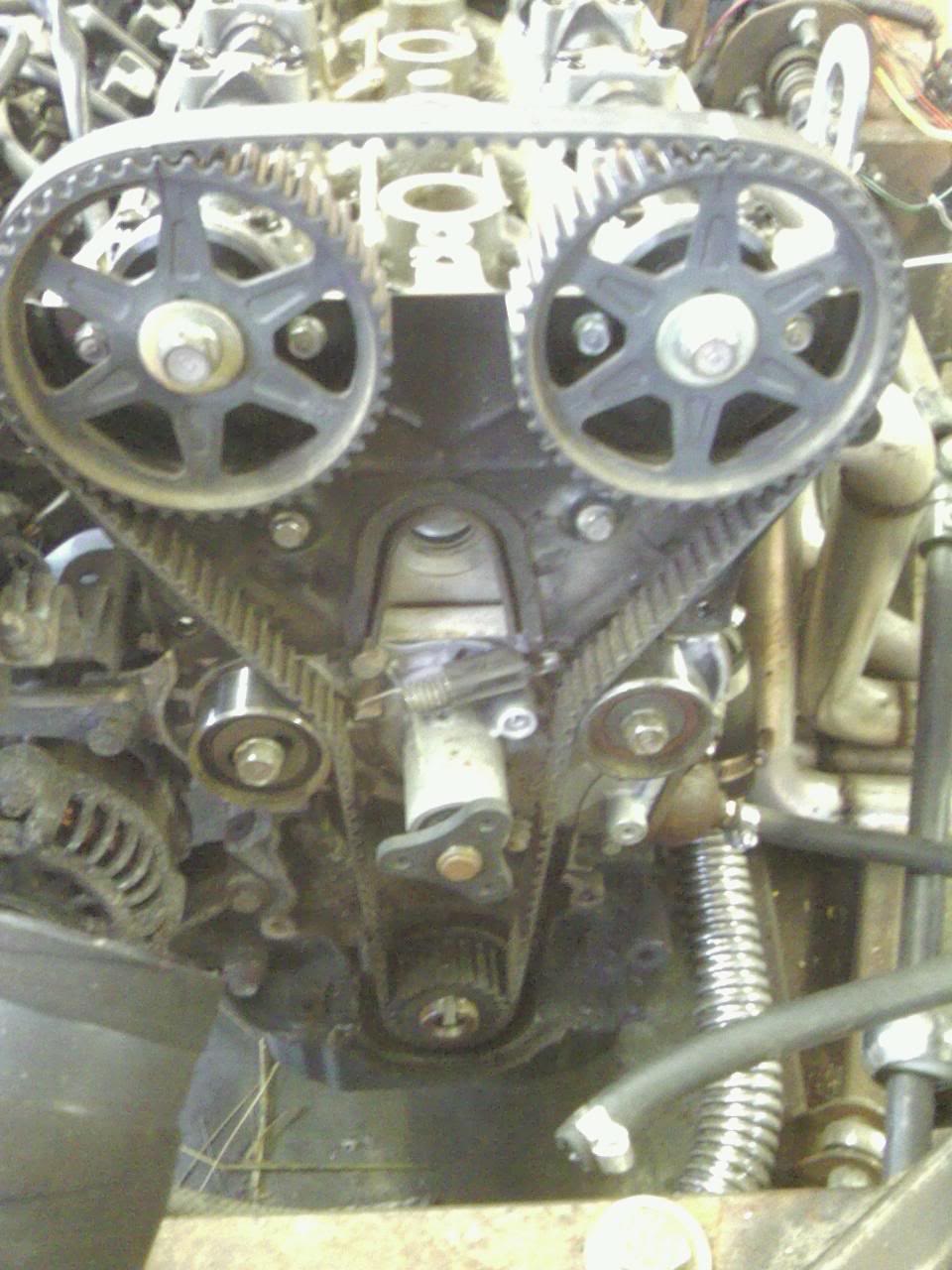
A side note I read after the fact, and that I would highly recommend to avoid such mentioned hassle and heightened blod pressure: on the cams, using the flat spots provided, use two box-end wrenches so that they cross BEFORE removing the tming belt. Apply a vise-grips to the crossed wrenches, and you will not have to spend time trying to re-set the timing.
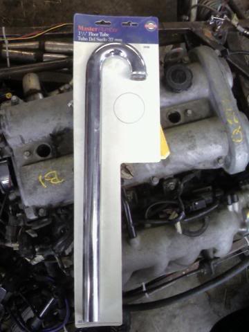
The rest of the reassembly went with little fanfare. Terry headed off, an Other Dave and I headed off the hardware store for bolts and to continue the hunt for 1.25 OD pipe and elbows, along with 1.25 ID hose for the radiator. After some searching, we came across a kitchen sink elbow. I bought it and headed back. While cutting it, I realized that it was chrome-plated copper, rather than the plastic we suspected.
Yes, that says Master Plumber.
We bolted everything into place, and cut some old factory hose to fit, and I filled the radiator. Other Dave bolted a block-off plate between the EGR valve and the intake, and checked everything over.
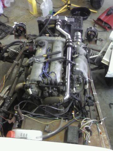
It runs! The timing wasn't wrong. Everything appears to be working, although I did not have time to keep it running long enough for the fan to kick in or the temp gauge to raise. I need to find a plug to cover the EGR bung in the cylinder 3 primary, and I want to go over the exhaust one mor time before removing it to fabricate the turbo manifold.
My next projects include advancing the timing from 10 to 14 or 16 degrees, once I can get a timing light, rebuilding the front brake calipers, and then locate the turbo and build a mounting bracket and start on the manifold. Progress at last!
I did considerable research on different reroute kits and conversions, varying from el cheapo, which leave the thermostat neck there, just blocking it off, to the $300+ kits with machined parts, and with all gaskets, bolts, etc included.
I managed to do my conversion for under 35 bucks, and I think it looks pretty good for a cheap temporary job.
I tried to figure out a way to avoid buying a spacer for the back water outlet, but I finally gave in and purchased a spacer ($15), a pair of gaskets ($3), a heater core bung ($5), longer bolts and washers ($2), and a chrome-plated copper sink J-bend (10.50).
I brought the spacer to work and a maintenance guy machined a lip into the spacer. Other Dave and I brought it to the in-laws and drilled and tapped for the heater line bung, and bought the gaskets.
I then started tearing down the motor to remove the original thermostat neck. That was the most time consuming part of the project, especially to consider I have not changed a timing belt before. Removing the thermostat neck requires removing the crank pulley, water pump pulley, cam gears, timing belt (obviously), and the valve cover.
I proceeded to disassemble the motor. However, once I got the thermostat neck off, I was unable to find a freeze lug to block off the water outlet before I had to head home.
It took three car dealerships and five auto stores to find the 30mm freeze plug I needed.
When I returned, I figured I would take half an hour to reassemble the front of the motor. WRONG. I found that the cams had moved under pressure from the marks I had made. Not having a manual at hand and not knowing how to reset timing, I hammered in the freeze plug and called it a day due to limited time.
Which leads to today. I researched more about timing, and no matter where I looked about belt changes, everyone kept saying Do Not Let Anything Move Or You Will Never Get I To Start Again, and every set of instructions were based that I had hypothetically followed that mantra.
So, I changed my search to "replacing broken timing belt" and quickly found that it I actually only have to line up the three marking points on the two cam sprockets and the crank sprocket to return to stock timing.
So, armed with new knowledge, I headed off to Other Daves, along with a Seven-hopeful and coworker, Terry, from work.
(Terry: My name is Terry and I want to build a Seven.
Chorus of voices: Hi, Terry!)
Theory and real life are completely different. With Terry's help, it took over an hour to get the timing belt bck on and just right. True, when I rebuild the other motor, it won't take half as long, but you have to learn sometime.
A side note I read after the fact, and that I would highly recommend to avoid such mentioned hassle and heightened blod pressure: on the cams, using the flat spots provided, use two box-end wrenches so that they cross BEFORE removing the tming belt. Apply a vise-grips to the crossed wrenches, and you will not have to spend time trying to re-set the timing.
The rest of the reassembly went with little fanfare. Terry headed off, an Other Dave and I headed off the hardware store for bolts and to continue the hunt for 1.25 OD pipe and elbows, along with 1.25 ID hose for the radiator. After some searching, we came across a kitchen sink elbow. I bought it and headed back. While cutting it, I realized that it was chrome-plated copper, rather than the plastic we suspected.
Yes, that says Master Plumber.
We bolted everything into place, and cut some old factory hose to fit, and I filled the radiator. Other Dave bolted a block-off plate between the EGR valve and the intake, and checked everything over.
It runs! The timing wasn't wrong. Everything appears to be working, although I did not have time to keep it running long enough for the fan to kick in or the temp gauge to raise. I need to find a plug to cover the EGR bung in the cylinder 3 primary, and I want to go over the exhaust one mor time before removing it to fabricate the turbo manifold.
My next projects include advancing the timing from 10 to 14 or 16 degrees, once I can get a timing light, rebuilding the front brake calipers, and then locate the turbo and build a mounting bracket and start on the manifold. Progress at last!
Reply
0
0


