RWyatt's "It's takin forever" Build Thread
 11-24-2014, 10:37 AM
#261
Senior Member
Thread Starter

Join Date: Dec 2007
Location: ATL
Posts: 1,348
Total Cats: 128
Question; I've got a Gen 2 MSPNP from DIY Autotune (yeah, I know, "WHY?!"). Anyway, given my foolhardyness and ignorance of everything that is right and pure, I'm wondering if it is at all possible to get my brand new EGT signal into the the sacred realm of the MSPNP?
I have a PLX SM-EGT that has a 0-5V output, but there's no way to get that signal to the MS. Everything I've read says, "...the CANBus connector allows interconnection of other MegaSquirt-compatible devices", and DIY offers a CAN-EGT interface (for $300!!) that should get a thermocouple signal into the PNP.
My question is; Is this (or something similar) my only option? (Other than selling the PNP and getting a real-man's ECU, with gobs of input channels, from Rev)

Reply
 0
0

0
11-26-2014, 11:15 AM
#262
Senior Member
Thread Starter
Join Date: Dec 2007
Location: ATL
Posts: 1,348
Total Cats: 128
OK, so no comments on the above - I'll take that to mean that the DIY interface is the only way to go with that.
Anyway...
I was doing the wiring for the gauges and was finding my layout difficult to deal with. The PLX module wiring was interfering with the spade lugs on the terminal block, and the terminal block itself was a bit difficult to get to (schematic below).
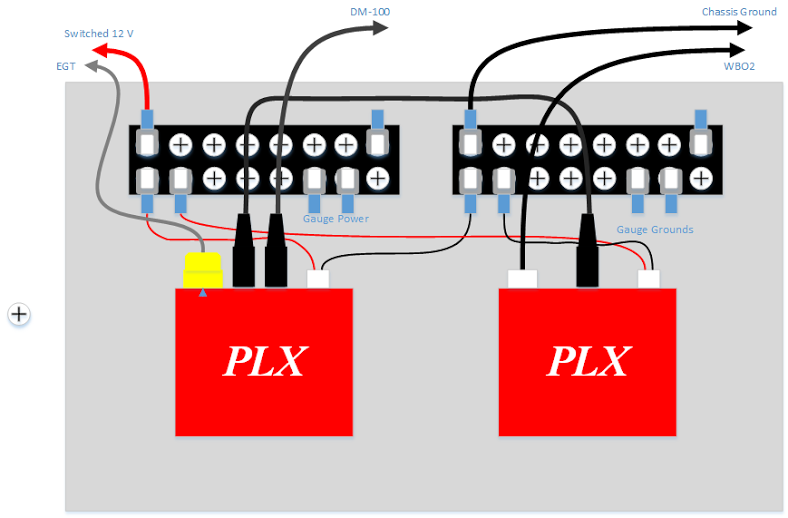
So what I've decided to do was to rearrange things so that the interference is reduced and the access is better. Here's what I've come up with;

That should make things easier to deal with. I may have to cut some notches (w/ grommets) in the bottom to clear the HVAC control panel. Gonna be get that done tonight and hopefully I'll get the dash in this weekend.
On a side note, I cleaned up the mounts for the pedals earlier this week (believe it or not, they were rusted). I'm debating on whether to paint them, or not (painting requires dis-assembly, and I'm not keen on doing that).
Anyway...
I was doing the wiring for the gauges and was finding my layout difficult to deal with. The PLX module wiring was interfering with the spade lugs on the terminal block, and the terminal block itself was a bit difficult to get to (schematic below).
So what I've decided to do was to rearrange things so that the interference is reduced and the access is better. Here's what I've come up with;
That should make things easier to deal with. I may have to cut some notches (w/ grommets) in the bottom to clear the HVAC control panel. Gonna be get that done tonight and hopefully I'll get the dash in this weekend.
On a side note, I cleaned up the mounts for the pedals earlier this week (believe it or not, they were rusted). I'm debating on whether to paint them, or not (painting requires dis-assembly, and I'm not keen on doing that).
Last edited by rwyatt365; 11-26-2014 at 11:34 AM.
Reply
0
0
12-15-2014, 12:00 PM
#263
Senior Member
Thread Starter
Join Date: Dec 2007
Location: ATL
Posts: 1,348
Total Cats: 128
Long time, no post. It's been relatively cold here and I ran out of money so things have been pretty static. What I have done (for mostly free) is;
- Swapped the orientation of the terminal strips and PLX modules per the drawing above.
- De-rusted and painted the brackets for the pedals.
- Same for the steering wheel shaft.
- Re-located the emergency flasher button into the space where the passenger ABS shutoff key was.
- Put an idiot light for low oil pressure into the place where the emergency flasher was.
- Started cutting new door cards (gonna use upper bolsters from an NA instead of the bulky NB door panels).
Pics when I get around to it.
What is holding me up is;
- "New", non-ABS master cylinder (the old tub had ABS, the new one doesn't so the brake plumbing is different).
- AN hoses for the turbo oil and water feeds
- A FPR from a NA (going to convert the returnless NB1 fuel system to a full-return system).
Some minor mods still to do;
- SS brake lines (because bling)
- HID projectors (because NB1 halogens suck)
- EGT input to the MSPNP2 (because inquiring minds want to know)
- Hinges for the (former) pass-side airbag cover
- Fabric for the NA door cards
- Miscellaneous wiring (oil temp & pressure, parallel fan mod)
Last edited by rwyatt365; 12-15-2014 at 01:51 PM.
Reply
0
0
12-16-2014, 07:57 AM
#264
Senior Member
Thread Starter
Join Date: Dec 2007
Location: ATL
Posts: 1,348
Total Cats: 128
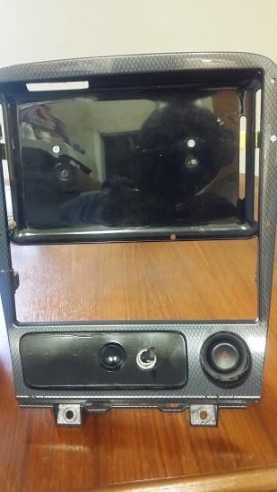
Here's the surround where the "ABS stuff" has been deleted and the start button and switch for the radiator fans are mounted. I'm going to drill another hole to the right of the start button and put an adjuster for the wiper delay there - probably will swap the start button and wiper delay around. Notice the hazard blinker switch in place of the cigarette lighter (I don't need no steenkin' lighter! I've got a 12v to USB converter behind the dash with 2 USB ports; 1 for the tablet power and an AUX port for my phone).
Also, tinted the rear lens and cleaned up the headlight covers (the rears are from an '01 and the headlight covers were dull and starting to yellow).
Also, tinted the rear lens and cleaned up the headlight covers (the rears are from an '01 and the headlight covers were dull and starting to yellow).
Reply
1
1
12-16-2014, 08:11 AM
#265

Looking good. I like the idea of the terminal box, just make sure everything is fused properly and if at all possible get a box with a cover.
No matter how many times I've told myself "after this, I'm finished with wiring" I still end up splicing back into something and my electrical OCD kicks in so it ends up being a much bigger project.
No matter how many times I've told myself "after this, I'm finished with wiring" I still end up splicing back into something and my electrical OCD kicks in so it ends up being a much bigger project.
Reply
0
0

 12-16-2014, 10:27 AM
#267
Senior Member
Thread Starter
Join Date: Dec 2007
Location: ATL
Posts: 1,348
Total Cats: 128
Thanks FAB and concealer404!
One question about grounds (bear in mind, I'm "electronically challenged"). On the 26-pin connector of the Gen 2 PNP there are two ground pins; pin 5 for chassis ground, and pin 22 for signal ground. Before I went through all of this re-wiring, neither of the above was connected to anything. I only had the WBO2 signal from the PLX module connected to pin 21.
My question(s)...should I start using these ground pins and - if so - should the PLX module(s) and the signal ground go to the "ground" terminal strip (which will be grounded to the metal backbone of the dash, which is in turn grounded to the chassis via it's bolts) OR can all three (the PLX modules, pin 5 and pin 22) all ground to the terminal strip?
Since I've gone through all of this trouble, I don't want to screw things up.
Reply
0
0


 The cold weather is helping to stave it off but every time I see another Miata on the road, I get sad.
12-17-2014, 09:17 AM
The cold weather is helping to stave it off but every time I see another Miata on the road, I get sad.
12-17-2014, 09:17 AM
#270
Senior Member
Thread Starter
Join Date: Dec 2007
Location: ATL
Posts: 1,348
Total Cats: 128
I've been doing some research on the subject of grounds and I ran into this thread talking about an oscillating AFR signal on a 91 (of course with a different ECU and WBO2 setup - which always makes things "fun").
What I can glean from the discussion is that I should ground the WBO2 controller to the ECU signal ground as close as possible to the ECU to avoid ground offsets. The trick is finding the right wire on the '99 harness for the ECU signal ground. I have a wiring schematic for a '00; the ECU signal ground seems to be on pin 3F (a Blk/Red wire) and the chassis ground seems to be on pins 3A, 3B and 3C. So what I'm going to do is to;
a) "Break" the ground terminal strip into two sections; one for chassis grounds, and another for signal grounds.
b) Tap into the ECU harness at pin 3F and run that to the "signal ground" portion of the grounds terminal strip.
c) Tap into the ECU harness at pin 3A and run that to the "chassis ground" portion of the grounds terminal strip.
d) Run the signal ground wire(s) from the PLX module(s) to the signal grounds on the terminal strip.
e) Run the power ground wire(s) from the PLX module(s) to the chassis grounds on the terminal strip.
The PLX documentation also recommends putting a 0.1uf cap between the WB signal and the signal ground at the ECU to filter out electrical noise. I'll plan for that, but leave it out unless I find it necessary.
Any comments?
Reply
0
0
12-17-2014, 10:43 AM
#271

Just as a quick background, I work at Freescale Semiconductor in the automotive development group and fixing bad grounds and signal integrity in OEM applications is a big part of my job.
Ground is such a misnomer and it is easily confused on what it does. If you're having noise problems, then there is one reason why; improperly managed electromagnetic fields. Every signal and power circuit needs its "power" and "ground" literally next to each other so your E and H fields are tight and minimize cross-talk with other circuits. Also, running fields 90� off axis from each other minimizes cross-talk, which is why wiring harnesses in-general are a stupid idea unless you also separate each signal with a corresponding ground wire...assuming that doesn't introduce a ground offset. Yes, it's complicated, and it's also why in-car buses like CAN are very popular and effective.
Practically speaking, you end up putting everything on the same "ground" and then literally keep each wire close to the grounded chassis. Splitting grounds is a recipe for creating ground offsets and is not a good idea.
Your PLX's, sensors, and ECU should all share the same ground.
Reply
4
4
12-17-2014, 11:51 AM
#272
Senior Member
Thread Starter
Join Date: Dec 2007
Location: ATL
Posts: 1,348
Total Cats: 128
Just as a quick background, I work at Freescale Semiconductor in the automotive development group and fixing bad grounds and signal integrity in OEM applications is a big part of my job.
Ground is such a misnomer and it is easily confused on what it does. If you're having noise problems, then there is one reason why; improperly managed electromagnetic fields. Every signal and power circuit needs its "power" and "ground" literally next to each other so your E and H fields are tight and minimize cross-talk with other circuits. Also, running fields 90� off axis from each other minimizes cross-talk, which is why wiring harnesses in-general are a stupid idea unless you also separate each signal with a corresponding ground wire...assuming that doesn't introduce a ground offset. Yes, it's complicated, and it's also why in-car buses like CAN are very popular and effective.
Practically speaking, you end up putting everything on the same "ground" and then literally keep each wire close to the grounded chassis. Splitting grounds is a recipe for creating ground offsets and is not a good idea.
Your PLX's, sensors, and ECU should all share the same ground.
Ground is such a misnomer and it is easily confused on what it does. If you're having noise problems, then there is one reason why; improperly managed electromagnetic fields. Every signal and power circuit needs its "power" and "ground" literally next to each other so your E and H fields are tight and minimize cross-talk with other circuits. Also, running fields 90� off axis from each other minimizes cross-talk, which is why wiring harnesses in-general are a stupid idea unless you also separate each signal with a corresponding ground wire...assuming that doesn't introduce a ground offset. Yes, it's complicated, and it's also why in-car buses like CAN are very popular and effective.
Practically speaking, you end up putting everything on the same "ground" and then literally keep each wire close to the grounded chassis. Splitting grounds is a recipe for creating ground offsets and is not a good idea.
Your PLX's, sensors, and ECU should all share the same ground.
Right now, I don't have a noise problem (my car is in pieces now). But before it got to this state there was a small - about 0.7 - oscillation in the AFR signal as registered by TunerStudio, and that was with neither ground from the MS connected to anything, but the PLX signal ground connected to chassis ground.
I'm all for simplicity (all grounds common and going to the ground point on the chassis) but I would like to have a cleaner AFR signal to tune by. If that happens with common grounds, GREAT.
Reply
0
0
12-17-2014, 03:24 PM
#273
Thanks for the feedback, every bit of information helps. I only have one question - if splitting the grounds is bad, why does the Gen2 MSPNP (from DIYAutotune) have a separate chassis ground and sensor ground on the 25-pin connector (not the ECU harness)?
Right now, I don't have a noise problem (my car is in pieces now). But before it got to this state there was a small - about 0.7 - oscillation in the AFR signal as registered by TunerStudio, and that was with neither ground from the MS connected to anything, but the PLX signal ground connected to chassis ground.
I'm all for simplicity (all grounds common and going to the ground point on the chassis) but I would like to have a cleaner AFR signal to tune by. If that happens with common grounds, GREAT.
To be practical in the car, you want all grounds at the same point, be it physically or electrically. Ground can be a plane [like a floorpan] or a single [effective] wire through the car. This is why most wiring in cars uses the steel unibody as ground, as any wire routed through the car has a fairly low magnetic field in by coupling to the steel.
If you wanted to tighten up your distribution blocks with the PLX boxes, use one block, with the power in the middle, grounds on either side, and signals on the outside. {signal, ground, +12V, ground, signal} This gives both power and signals their own field spaces. The way you drew them above has the power and ground really far apart, making the magnetic field very big and allowing the signals to be corrupted.
Reply
2
2

 12-21-2014, 11:06 AM
#278
Senior Member
Thread Starter
Join Date: Dec 2007
Location: ATL
Posts: 1,348
Total Cats: 128
Did some work yesterday cuttin' out some new door cards;
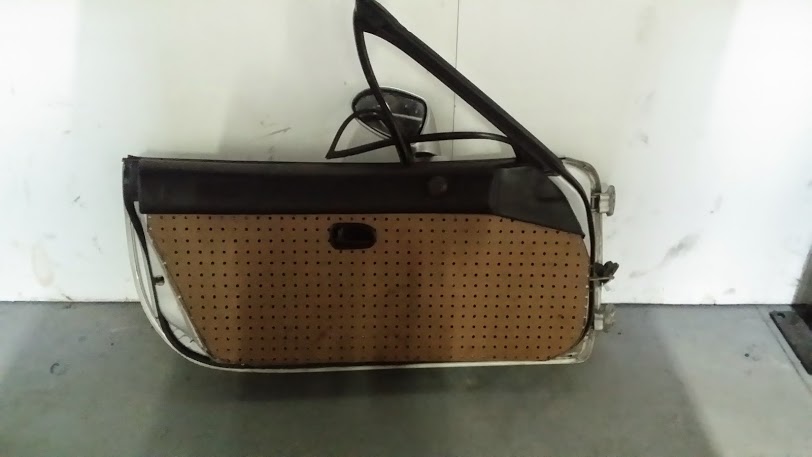
I'm using the upper bolsters from a NA and cutting the cards out of pressboard. Once I have a final shape with all of the holes located I'll upholster the cards to make 'em purrrty! I'll also have to figure out some kind of armrest, but that's secondary (can I "adapt" a NA armrest?).
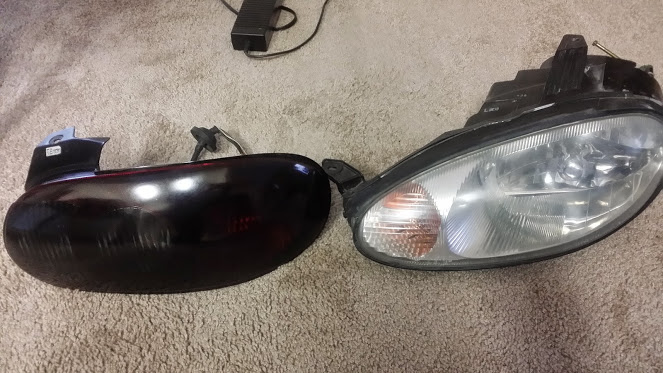
I had also ordered a non-ABS MC, prop-valve and booster from The Partsgroup. The unit was from a non-ABS NB2 and I thought it would be PNP into my non-ABS NB1 tub (remember, my original car was an ABS NB1). Was I wrong! The "original" is on the right, the "replacement" is on the left.
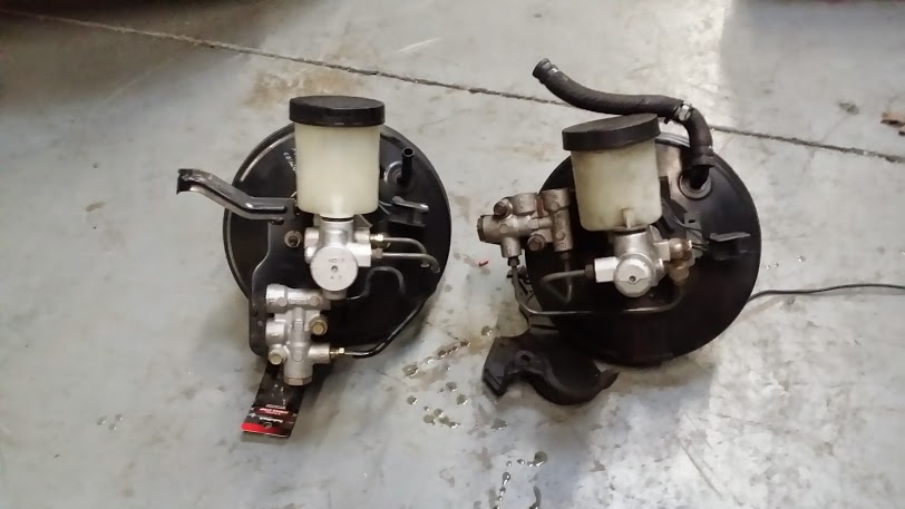
I already knew that the plumbing on the MC was different; what I didn't know was that the orientation of the prop-valve on the NB2 unit was completely different! I was planning that I'd have to bend a few brake lines to make things fit. Now I'll have to swap the NB1 prop-valve bracket onto the NB2 booster so that the valve will be in the general vicinity of the front brake lines. And even then I'll have to make brand new lines to get from the MC to the (relocated) prop-valve.
More unintended work....DAMN, this is "taking FOREVER!"
I'm using the upper bolsters from a NA and cutting the cards out of pressboard. Once I have a final shape with all of the holes located I'll upholster the cards to make 'em purrrty! I'll also have to figure out some kind of armrest, but that's secondary (can I "adapt" a NA armrest?).
I had also ordered a non-ABS MC, prop-valve and booster from The Partsgroup. The unit was from a non-ABS NB2 and I thought it would be PNP into my non-ABS NB1 tub (remember, my original car was an ABS NB1). Was I wrong! The "original" is on the right, the "replacement" is on the left.
I already knew that the plumbing on the MC was different; what I didn't know was that the orientation of the prop-valve on the NB2 unit was completely different! I was planning that I'd have to bend a few brake lines to make things fit. Now I'll have to swap the NB1 prop-valve bracket onto the NB2 booster so that the valve will be in the general vicinity of the front brake lines. And even then I'll have to make brand new lines to get from the MC to the (relocated) prop-valve.
More unintended work....DAMN, this is "taking FOREVER!"
Reply
0
0
12-22-2014, 01:31 PM
#279
Senior Member
Thread Starter
Join Date: Dec 2007
Location: ATL
Posts: 1,348
Total Cats: 128
Put the window glass back into the door (above) and took the time to grease the tracks - this window at least should slide up and down "like buttah".
Also discovered that the VICS actuation components on my IM are all FUBAR'ed; the bottom nipple on the solenoid valve is broken off (I didn't know this), and the nipple on the vacuum can is broken as well (I knew about this). That means I was driving around with a massive vacuum leak and my wonderful VE map is crap!
And to make matters worse, no one wants to sell me just these components - only a whole IM! All of the Miata-savvy part places won't part out these tidbits, and non-Miata places just say, "What's a VICS actuator?" Looks like I have three options;
1. Try to super-glue the nipples back on (sounds kinky). Tried that with the vac-can, didn't work.
2. Wire the VICS butterflys closed and give up the high-RPM kick.
3. Buy an IM and scavenge (not likely since I just found out on Friday that the contract that I'm working on will NOT be renewed for 2015, so I'm out of a job as of 12/31 - "Happy New Year!").
Looks like #2 will be my (free) choice until I get back to work.
Reply
0
0
12-23-2014, 01:26 AM
#280
Elite Member
iTrader: (37)

Join Date: Apr 2010
Location: Very NorCal
Posts: 10,441
Total Cats: 1,899
Option 2 seems to have worked well for the nipple that got broken off my actuator. Just don't glue it shut 
Bloody hell, I'm going to have the same problem with the master cylinder plumbing thing. Thanks for posting that. Do you think hardlines from a non-ABS NB2 work?
Bloody hell, I'm going to have the same problem with the master cylinder plumbing thing. Thanks for posting that. Do you think hardlines from a non-ABS NB2 work?
Reply
0
0


