RWyatt's "It's takin forever" Build Thread

 10-06-2014, 01:57 PM
#222
Senior Member
Thread Starter

Join Date: Dec 2007
Location: ATL
Posts: 1,346
Total Cats: 128
Spent the weekend;
- Painting the calipers ("Ricer Red" BTW)
- Removing the old front rotors (got nice, shiny, new NAPA rotors)
- Removing and rust-proofing the rear top-hats
- Figuring out what size shims are needed for the valvetrain (I only checked the exhaust side on the first rebuild because the Supertech valves were taller than stock, this time I did the Whole Enchilada)
- Took pic's of the rat's nest of wiring under the hood so that I can try to clean things up on re-assembly.
That's one thing that frightens me most of all about all of this...WIRING. Me 'n electricity have a love/hate relationship (it loves to torture me and I hate everything about it).

Reply
 0
0

0
10-08-2014, 11:39 AM
#223
Senior Member
Thread Starter
Join Date: Dec 2007
Location: ATL
Posts: 1,346
Total Cats: 128
Ok, I've got the new valve spacer shims on order (should be here tomorrow), so I can get the head all assembled and clearanced when that gets here. The new rings should be here as well. I've disassembled the oil pump and cleaned it - it was in pretty good shape, nothing of note inside (whew).
Other stuff; I've got two main areas of concern: 1) the electrical wiring (mentioned before), and 2) the brakes.
Wiring:
Most of the harness is in-place on the "new" tub (thankfully), but I've made some modifications to the "old" wiring over the years, most notably...
- The dual-fan mod with a switch on the console, so that not only do both fans run when the thermostat reaches the set-temp but I can also flip a switch and turn them on when I so choose.
- A fuel pump switch, so that I can turn on the pump on-demand. I put this in when I was having some issues with fuel pumps (years ago) and I wanted to be able to control them manually.
- A master relay "manual bypass", where can I unplug the master relay and plug two heavy gauge wires into the circuit - leading to a HD 30 amp switch in the cockpit - so that I can be my own "relay". I did that because I was having problems with the main relay overheating and causing no-starts.
- A "NA alternator mod" (documented earlier in this thread) to get rid of the troublesome, expensive 99 alternator with the integrated voltage regulator.
- And lastly, a "Professionally Installed" alarm system (w/ motion activation and remote start). This was necessity when I lived in DTW, not so much so now. Looking at the bare wiring harness now I question the "professional-ness" of the installation (lotsa of electrical tape, vampire taps into the stock harness, components just stuffed into place). Other than knowing what to tap into, it's no better than I would have done. I think I'll just leave this one out.
Brakes:
The old car had ABS, the new tub didn't (no ABS block in the engine bay, and no wiring for the ABS module in the cabin). That's cool because I haven't had an active ABS system in the old car for several years. The only issue there is that the brake line routing in the new car doesn't "fit" the lines that I would transfer from the old car.
I've been searching today for a definitive schematic that shows what is the brake line routing for the whole car. I haven't found anything yet, but I think I can piece together what goes where. I'm thinking of putting in an adjustable proportioning valve (because the stock one from the ABS-car may not have the F/R bias correct for a non-ABS car). Thoughts? Suggestions?
I'm thinking that this weekend will be spent trying to figure out what wires go where, and replicating my mods...but neater. Also, I think I'll attempt to dye the carpet (the new shell has tan carpet - that'll go to black). The days leading up this will go towards prepping for this.
Reply
0
0
10-10-2014, 02:32 PM
#224
Senior Member
Thread Starter
Join Date: Dec 2007
Location: ATL
Posts: 1,346
Total Cats: 128
In the interests of full disclosure and to assist the unwary, I offer this (new) tale of woe...
So, I decided - after carefully Plastigaging my brand new main bearings (satisfactorily, if I must say so) and making sure that the crank spun freely - to remove the bypass plunger on the oil pump and make sure that it was nice and shiny. My crappy old snap ring pliers weren't able to compress the snap ring on the BE pump enough, so I did a little "tweaking" to get them to close a little bit tighter. After the tweak I gave them one more try and...yes, you guessed it...the snap ring came free just about the time that I decided to divert my attention and - SPROING - the spring shot the ring to kingdom come.

Now I don't know if you've tried to find a snap ring that was forcibly ejected from it's resting place, but I'm sure that it's in the same place that un-paired socks, loose change and children threatened with domestic chores go to. Anyway, the ring is long gone, so I'll have to source a generic replacement. The silver-lining is that the plunger was not freely moving in the bypass bore. I can only think that some crud got in there from the spun bearing and caused the plunger to seize (the other alternative is that the plunger NEVER moved freely in the bore, but I refuse to believe that a $400+ pump came defective out of the box...and I believe in the Tooth Fairy and Santa Claus).
I'll be seeing what I can do the rectify that problem tonight. Then tomorrow will be "Carpet Dying Day"!!
So, I decided - after carefully Plastigaging my brand new main bearings (satisfactorily, if I must say so) and making sure that the crank spun freely - to remove the bypass plunger on the oil pump and make sure that it was nice and shiny. My crappy old snap ring pliers weren't able to compress the snap ring on the BE pump enough, so I did a little "tweaking" to get them to close a little bit tighter. After the tweak I gave them one more try and...yes, you guessed it...the snap ring came free just about the time that I decided to divert my attention and - SPROING - the spring shot the ring to kingdom come.
Now I don't know if you've tried to find a snap ring that was forcibly ejected from it's resting place, but I'm sure that it's in the same place that un-paired socks, loose change and children threatened with domestic chores go to. Anyway, the ring is long gone, so I'll have to source a generic replacement. The silver-lining is that the plunger was not freely moving in the bypass bore. I can only think that some crud got in there from the spun bearing and caused the plunger to seize (the other alternative is that the plunger NEVER moved freely in the bore, but I refuse to believe that a $400+ pump came defective out of the box...and I believe in the Tooth Fairy and Santa Claus).
I'll be seeing what I can do the rectify that problem tonight. Then tomorrow will be "Carpet Dying Day"!!
Reply
0
0
10-13-2014, 10:04 AM
#225
Senior Member
Thread Starter
Join Date: Dec 2007
Location: ATL
Posts: 1,346
Total Cats: 128
Well it rained Saturday morning, so all I could do was to clean the old carpet - the dye/paint will have to wait.
What I did accomplish was to get the head mounted onto the block and the shims on the intake side installed. I realized (too late) that I had ordered the wrong shims for the exhaust side (DAMMIT!!) so I couldn't get that side finished.
I did find the right snap ring for the oil pump bypass at my favorite high-performance shop (Lowes Racing Supply). I tried every "auto parts store" and the few places that knew what I was talking about didn't have them in stock. I walked into a random Lowes, went to the parts drawers and found what I needed in 5 minutes.
Reply
0
0
10-20-2014, 08:19 AM
#226
Senior Member
Thread Starter
Join Date: Dec 2007
Location: ATL
Posts: 1,346
Total Cats: 128
Nothing much to report. I'm in "stall mode". I had ordered the wrong size shims for the cam followers and now I have 4 buckets without any shims.
Because the Supertech stems on the exhaust valves are 6mm longer than stock, I have to order non-standard thickness shims. I only found two sources for the size 27mm shims that I'm looking for; Cylinder Head Supply which requires that you buy shims in sets of 4 at $20 per set, and Industrial Supply Warehouse where you can buy the shims singly but their delivery times are stupid-long. I ordered from ISW and have been waiting a week now for the shims to arrive. I have a tracking number but that only shows "Shipment information supplied" (WTF does THAT mean?).
So, I finished dyeing the carpet, and pulling out the rest of the wiring harness. I also pulled the head and tail lights and painted the front hubs. I'm gonna take the water mixing manifold and tubes for the heater core to a welder to have 10-AN bungs welded on so that I can swap the rubber heater lines for braided lines. I've also gotten some fittings so that I can source the oil and water feeds for the turbo from the outlets on the block (yes, I have an early 1.8 block with those feeds on the block - lucky me).
My "other project" is to fit a little instrument "blister" to the top of the dashboard. I'm planning for some new gauges - EGT and Oil Temp - and I don't want to put them into a window pillar mount (because NOT ricer). I've got a neat little gauge pod from Summit and I'm trimming it to fit the curve of the dash, just above the eyeball vents. My goal is to mount the boost and AFR gauges into the eyeball vent spaces and have the temp gauges above (or vice-versa, we'll see).
Something to waste time until the shims arrive. Gotta do something to show progress!
Reply
0
0
10-21-2014, 09:32 AM
#227
Senior Member
Thread Starter
Join Date: Dec 2007
Location: ATL
Posts: 1,346
Total Cats: 128
So, while I'm wasting time until the valve shims arrive I un-boxed the new NAPA front rotors that I bought 3 weeks ago and discovered that one had holes for 4 lugs (good), and was vented (good), and the other had holes for 5 lugs (?) and was solid (??) - obviously something was wrong. I checked the part numbers on the boxes and they both had the same part number on the box. So I called NAPA and (after a few inane questions) the "NAPA-guy" admitted that the part in the box was the wrong part (no sh*t).
So now I get to go back and swap the disc for the right part this afternoon (it was too late to do it yesterday). Thank you Mr NAPA.
I did manage to get the steel subframe separated from the dash last night (so many screws, hope I get them back in the right place when it comes time to put it all back together). I'm gonna drill holes for mounting the gauge pod and figure out routing for the wires for the gauges tonight...
...if those damned shims STILL aren't in!!!
PS - I might just order some from CHS, at least I can trust their shipping. It just pisses me off that I have to buy a set of 4 for a size, and I've got to buy 4 different sizes.
Reply
0
0
10-21-2014, 11:48 AM
#228
Senior Member
Thread Starter
Join Date: Dec 2007
Location: ATL
Posts: 1,346
Total Cats: 128
A question for the community...
First, some history:
I've already got a coolant reroute using a BEGI spacer at the back of the head. I'm going to be replacing the rubber lines for the heater core with -AN fittings and hose (mainly because one of the heater core lines runs dangerously close to the downpipe and I can route and protect the braided hose better than I can the rubber). I'm sourcing the turbo and heater core feeds from the two 3/8 NPT ports on the spacer.
With the BEGI spacer I have two alternatives for the placement of the thermostat;
1) Directly on the head. This "traps" cold water in the block until it warms up enough for the thermostat to open. But this also prevents flow to the turbo water feed and the heater core during the warmup period.
2) Just below the waterneck for the return line. This still prevent flow to the radiator during warmup but allows flow to the turbo and heater water lines.
My quandary;
In Position #1, wouldn't the engine warm up quicker without the flow through the heater core, but at the expense of flow through the turbo? Also, wouldn't the initial water temp readings be screwy because of no-flow past the temp sensor during warmup?
In Position #2, wouldn't my initial temps be more reliable (because there's always water flowing past) but at the expense of longer warmups because there's always water flowing through the heater core (a mini-radiator)? Couldn't I solve that by putting one side of an oil thermostat in-line with the source leg of the heater core lines (as in, prevent flow through the heater until the water temp goes above 160)?
Or should I just K.I.S.S. and move on...
Reply
0
0
10-21-2014, 12:08 PM
#229
Elite Member
iTrader: (37)

Join Date: Apr 2010
Location: Very NorCal
Posts: 10,441
Total Cats: 1,899
I think you are overthinking this. The "longer warmup times" due to heater core seems to be a non issue. My M-Tuned is effectively routed as your #2 option and I have zero issues even on the coldest of days (here in coastal CA that might be a joke) as long as I don't turn the heater on until the engine is semi warmed up.
I would postulate that the turbo would add more heat that the heater core removes, provided the fan is off.
I would postulate that the turbo would add more heat that the heater core removes, provided the fan is off.
Reply
0
0
10-21-2014, 12:16 PM
#230

With the BEGI spacer I have two alternatives for the placement of the thermostat;
1) Directly on the head. This "traps" cold water in the block until it warms up enough for the thermostat to open. But this also prevents flow to the turbo water feed and the heater core during the warmup period.
2) Just below the waterneck for the return line. This still prevent flow to the radiator during warmup but allows flow to the turbo and heater water lines.
I currently have my OEM sensor in the BEGi block running to my AEM and then a stand alone Innovate Coolant Temp gauge with the probe directly in the cylinder head and when I moved the t-stat the readings did reflect a difference.
In summary you don't want your t-stat to block off your temp sensor.
Last edited by FAB; 10-21-2014 at 12:51 PM.
Reply
0
0
10-21-2014, 02:10 PM
#231
Senior Member
Thread Starter
Join Date: Dec 2007
Location: ATL
Posts: 1,346
Total Cats: 128
I think you are overthinking this. The "longer warmup times" due to heater core seems to be a non issue. My M-Tuned is effectively routed as your #2 option and I have zero issues even on the coldest of days (here in coastal CA that might be a joke) as long as I don't turn the heater on until the engine is semi warmed up.
I would postulate that the turbo would add more heat that the heater core removes, provided the fan is off.
I would postulate that the turbo would add more heat that the heater core removes, provided the fan is off.
PS - if I was still in DTW, heater warmup would be a REAL issue. Not as bad here in ATL, but still there are enough sub 30-degree mid-winter nights that having a functioning heater is still a concern.
There is really only one way to do this properly because of the placement of your water temp sensor (if it's in the BEGi block). For example if you mount the t-stat directly to the head and the BEGi block on top of it, you're blocking your coolant temp sensor from actual engine temps. While this might not make that big of a difference your coolant temp readings won't be entirely accurate during warm-up.
I currently have my OEM sensor in the BEGi block running to my AEM and then a stand alone Innovate Coolant Temp gauge with the probe directly in the cylinder head and when I moved the t-stat the readings did reflect a difference.
In summary you don't want your t-stat to block off your temp sensor.
I currently have my OEM sensor in the BEGi block running to my AEM and then a stand alone Innovate Coolant Temp gauge with the probe directly in the cylinder head and when I moved the t-stat the readings did reflect a difference.
In summary you don't want your t-stat to block off your temp sensor.
Reply
0
0
10-21-2014, 10:54 PM
#233
SADFab Destructive Testing Engineer


iTrader: (5)
Join Date: Apr 2014
Location: Beaverton, USA
Posts: 18,642
Total Cats: 1,866
Another reason to put the thermostat behind the spacer is to allow coolant flow through the block while the thermostat is closed. Its actually kind of the main reason for having a spacer there. If coolant had another path through the block besides the heater core then there would be no need for the spacer.
Reply
0
0
10-22-2014, 08:34 AM
#234
Senior Member
Thread Starter
Join Date: Dec 2007
Location: ATL
Posts: 1,346
Total Cats: 128
Another reason to put the thermostat behind the spacer is to allow coolant flow through the block while the thermostat is closed. Its actually kind of the main reason for having a spacer there. If coolant had another path through the block besides the heater core then there would be no need for the spacer.
Reply
0
0
10-22-2014, 09:24 AM
#235
SADFab Destructive Testing Engineer
iTrader: (5)
Join Date: Apr 2014
Location: Beaverton, USA
Posts: 18,642
Total Cats: 1,866
But it has all the ports taped in it so you can have flow while the thermostat is closed. Otherwise coolant would just sit in the block and heat up.
Reply
0
0
10-23-2014, 07:08 AM
#236
Senior Member
Thread Starter
Join Date: Dec 2007
Location: ATL
Posts: 1,346
Total Cats: 128
Got the right brake rotor from NAPA yesterday (made SURE to open the box in the store to make sure it was the right part this time).
Also did a test-fit of the gauge pod. This is what it looks like;
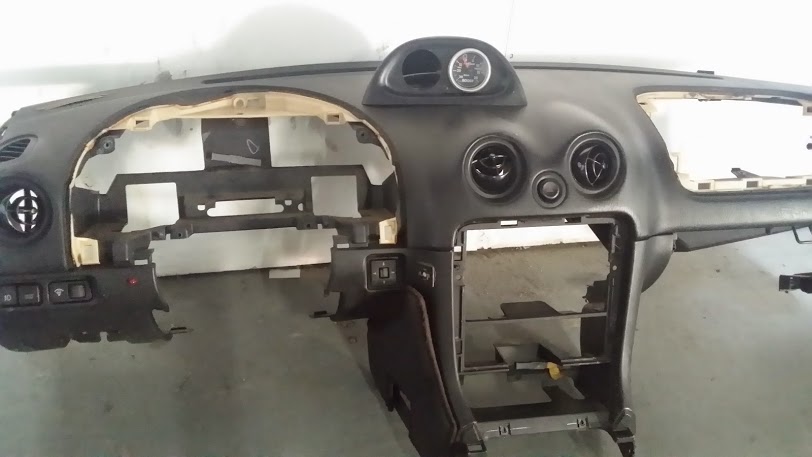
Still have a bit of trimming to do so that there aren't any gaps, but as it is it'll do nicely. And, yes, it's aimed slightly towards the driver for better visibility.
I found some valve shims from a different source (K-Line?), they should be here tomorrow so I can finally put the engine together! Industrial Parts House is saying, "We don't know what happened...". My guess is that the package is lost in the fender well of a UPS truck in Des Moines and it'll show up the day after I button up the engine.
Also did a test-fit of the gauge pod. This is what it looks like;
Still have a bit of trimming to do so that there aren't any gaps, but as it is it'll do nicely. And, yes, it's aimed slightly towards the driver for better visibility.
I found some valve shims from a different source (K-Line?), they should be here tomorrow so I can finally put the engine together! Industrial Parts House is saying, "We don't know what happened...". My guess is that the package is lost in the fender well of a UPS truck in Des Moines and it'll show up the day after I button up the engine.
Reply
0
0
10-27-2014, 08:33 AM
#237
Senior Member
Thread Starter
Join Date: Dec 2007
Location: ATL
Posts: 1,346
Total Cats: 128
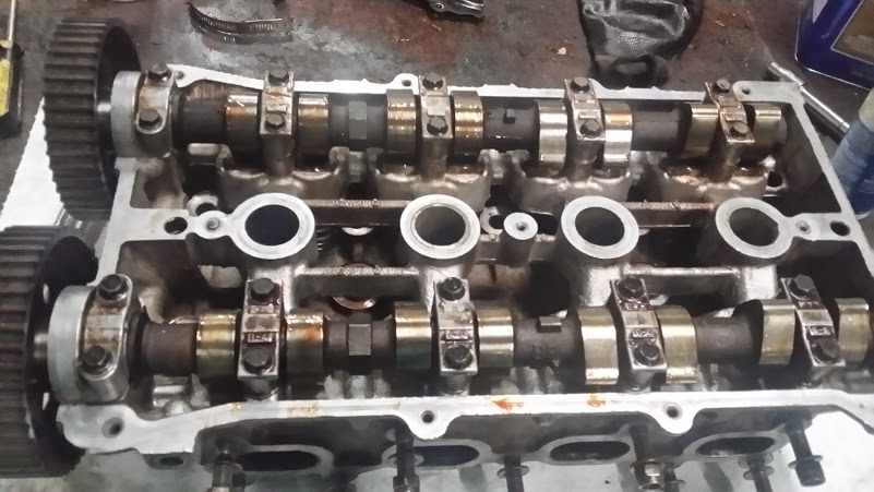
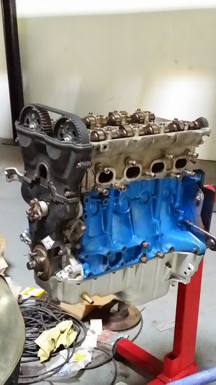
Got the shims on Thursday (from vendor #2, then the one's from vendor #1 showed up on Friday!), so the head is all assembled and on the engine;
My calipers went from this;
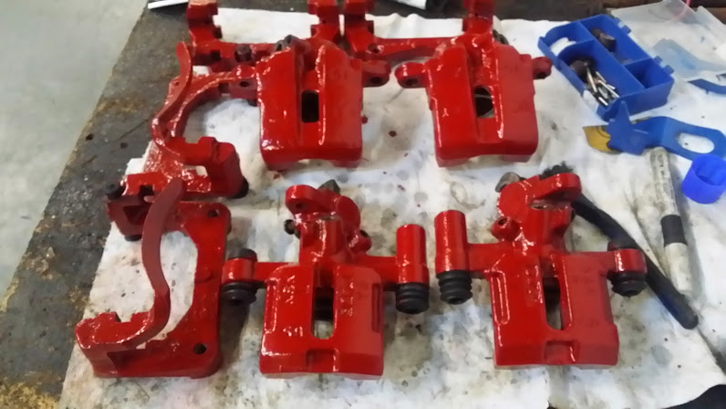
to this;

And I painted the metal frame that's underneath the dashboard;

I know it'll never see the light of day after it's in the car, but why not?
Next on the menu is to prep for putting a Nexus 7 into the dash (fur-real this time). I've already got the tablet and I just ordered a Scosche wiring harness and amp interface, a Behringer audio interface and a generic OTG splitter. We'll see if the electron-devils will get me (again).
My calipers went from this;
to this;
And I painted the metal frame that's underneath the dashboard;
I know it'll never see the light of day after it's in the car, but why not?
Next on the menu is to prep for putting a Nexus 7 into the dash (fur-real this time). I've already got the tablet and I just ordered a Scosche wiring harness and amp interface, a Behringer audio interface and a generic OTG splitter. We'll see if the electron-devils will get me (again).
Reply
0
0
10-30-2014, 12:15 PM
#238
Senior Member
Thread Starter
Join Date: Dec 2007
Location: ATL
Posts: 1,346
Total Cats: 128
Question regarding DIY braided hoses;
I'm planning to replace the water lines to/from the turbo and heater core with braided hose.
a) Because the turbo water lines are part rubber, part braided (this was an early concession to the all-rubber lines that were first used - which deteriorated after a year), and b) because the hard pipe from the mixing manifold puts the heater core return too close to the downpipe.
Anyway, my questions are;
1) PTFE, or "regular" core? I was thinking about the Earl's Perform-O-Flex hose. Is that adequate (overkill)?
2) Has anyone used, or recommend the "Black Series" hose ends from ATP Turbo? They're $8-10 less than Earl's hose ends and I'm wondering why?
Reply
0
0
10-31-2014, 07:24 AM
#239
Senior Member
Thread Starter
Join Date: Dec 2007
Location: ATL
Posts: 1,346
Total Cats: 128
Still waiting for the audio stuff to trickle in. So, in the meantime I've made a "Super Boomslang" harness;
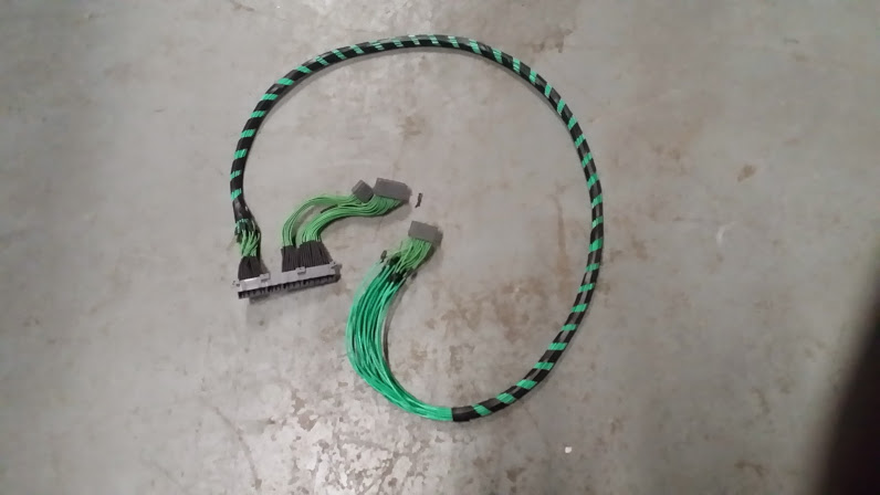
Basically, the regular Boomslang with the 22-pin connector extended so that the connector from the interior can plug into the harness, while the two other connectors that come from the engine bay can fold over to the passengers side of the cabin...like this;
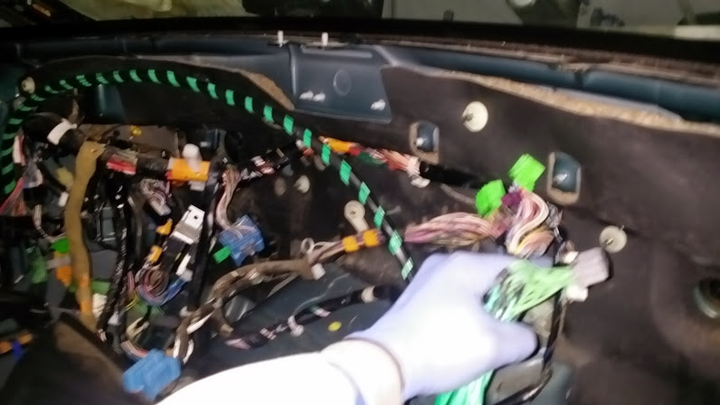
yeah it's blurry (try holding the camera in one hand while trying to gather the three connectors in the other hand while they try to twist out of your hand). Anyway, the goal is to mount the Megasquirt and the stock ECU into the space where the passengers airbag was;
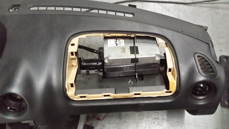
'Cause in Georgia we have to do an annual "Emissions Test" with the OBD port plugged into the state's computer. So, once a year, I have to have an operational OBD port and this makes it easy to swap the plugs between the MS and stock ECU (as opposed to standing on my head trying to fish through the rat's nest under the dash).Besides, this mounting of the MS is a lot prettier than slung under the steering column with tie-wraps. I'm gonna figure a way to hinge the airbag cover so it's "easy-access".
Other than that, I test-fit the gauges into the pod on top of the dash and in the eyeball vent;
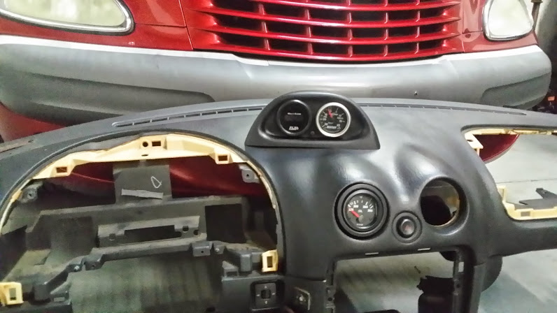
So, boost and AFR go into the pod, and EGT and oil temp will replace the center eyeball vents.
PS - Also got new rear rotors. Went the O'Reilly and - believe it or not - they were the RIGHT PART!!
Basically, the regular Boomslang with the 22-pin connector extended so that the connector from the interior can plug into the harness, while the two other connectors that come from the engine bay can fold over to the passengers side of the cabin...like this;
yeah it's blurry (try holding the camera in one hand while trying to gather the three connectors in the other hand while they try to twist out of your hand). Anyway, the goal is to mount the Megasquirt and the stock ECU into the space where the passengers airbag was;
'Cause in Georgia we have to do an annual "Emissions Test" with the OBD port plugged into the state's computer. So, once a year, I have to have an operational OBD port and this makes it easy to swap the plugs between the MS and stock ECU (as opposed to standing on my head trying to fish through the rat's nest under the dash).Besides, this mounting of the MS is a lot prettier than slung under the steering column with tie-wraps. I'm gonna figure a way to hinge the airbag cover so it's "easy-access".
Other than that, I test-fit the gauges into the pod on top of the dash and in the eyeball vent;
So, boost and AFR go into the pod, and EGT and oil temp will replace the center eyeball vents.
PS - Also got new rear rotors. Went the O'Reilly and - believe it or not - they were the RIGHT PART!!
Reply
0
0


