Ryephile's loosely guided build

 05-07-2015, 11:38 PM
#102
Junior Member

Thread Starter
iTrader: (1)

Join Date: Jun 2014
Location: Metro Detroit
Posts: 270
Total Cats: 26
Some cool pictures from Killboy.com from last weekend.
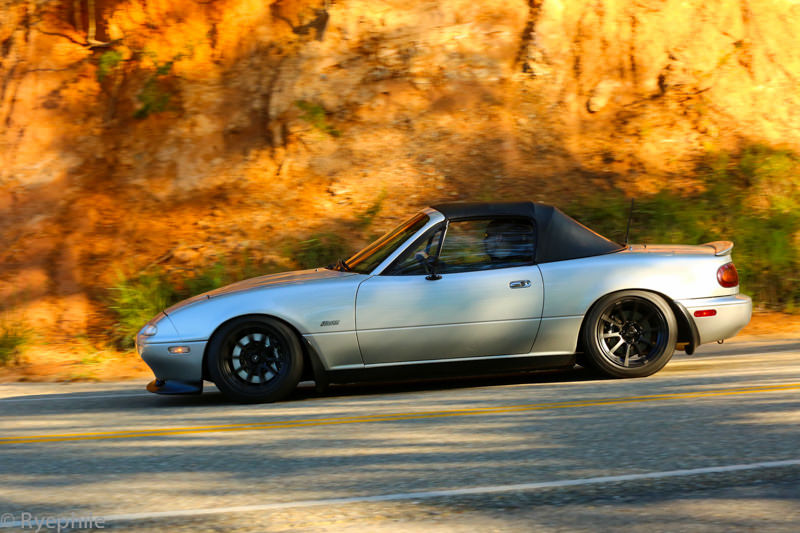 737780.jpg by Ryephile, on Flickr
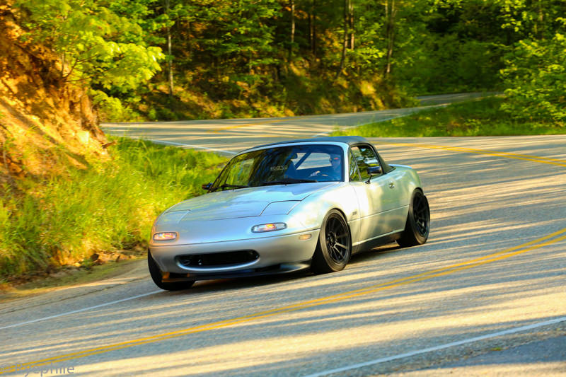 737779.jpg by Ryephile, on Flickr
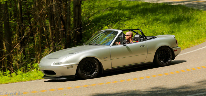 737783.jpg by Ryephile, on Flickr
737780.jpg by Ryephile, on Flickr737779.jpg by Ryephile, on Flickr737783.jpg by Ryephile, on Flickr

Reply
 0
0

0
05-19-2015, 10:46 PM
#103
Junior Member
Thread Starter
iTrader: (1)
Join Date: Jun 2014
Location: Metro Detroit
Posts: 270
Total Cats: 26
Busy day.
Went here:
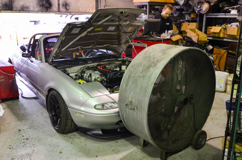 RYE_0193.jpg by Ryephile, on Flickr
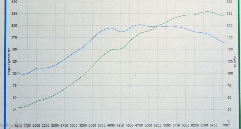
232 wHP and 208 LbFt at 10 psi on 93 octane. Perfect for keeping the con-rods and 5-speed in the car in functioning condition. Obviously the boost threshold isn't accurately demonstrated in the plot; on the street in 5th gear target boost occurs at 3.0k RPM. The dip at 4300 on the plot is an artifact of the current boost controller setup, not a VE dip.
Discovered some interesting stuff about injection timing, picked up 10% torque for a notable region of part throttle. Perfected the VE table, did some ignition timing investigation, spot-checked the X-Tau [working perfectly], and did some thermal capacity checks [quite impressive].
Discovered the SwainTech White Lightning is so opaque you can't see the manifold glow red even during sustained peak torque. The closest proximity item to the manifold is the heater hose, and that showed a post-pull IR reading of 170F, which isn't even coolant temp. Impressive.
 RYE_0225.jpg by Ryephile, on Flickr
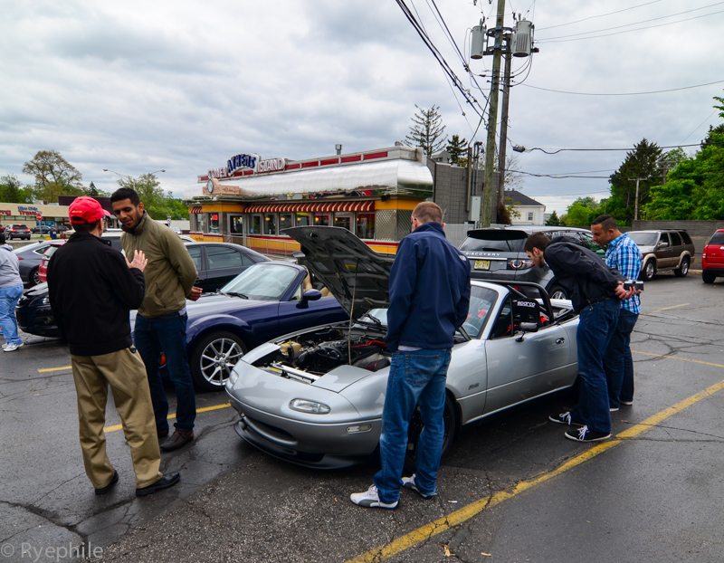
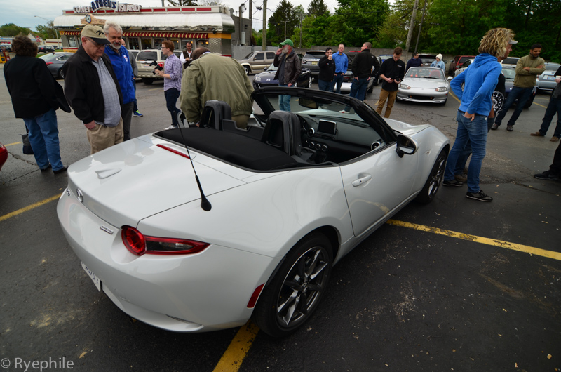
Then went to Autoblog's Miata ND reveal on Woodward. A surprising number of Miatae showed up. I was one of three boosted; the other two were both NC's. The demographic was as-expected; hipsters being supes fab and fat old white men pretending they still fit in the car.
 RYE_0195.jpg by Ryephile, on Flickr
 RYE_0213.jpg by Ryephile, on Flickr
 RYE_0196.jpg by Ryephile, on Flickr
Panel fitment not so hot
 RYE_0204.jpg by Ryephile, on Flickr
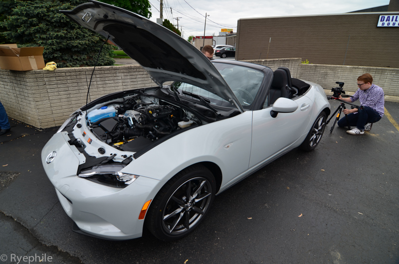
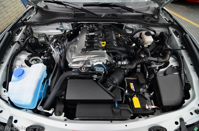
Learned from a Mazda engineer that the Skyactiv runs Atkinson cycle only for some of part-load, then uses it's 70 degrees of intake cam phasing to run Otto at WOT. He alleged they were able to run de-throttled during Atkinson, which sounds fishy to me without any valve-lift capability.
 RYE_0199.jpg by Ryephile, on Flickr
Went here:
RYE_0193.jpg by Ryephile, on Flickr232 wHP and 208 LbFt at 10 psi on 93 octane. Perfect for keeping the con-rods and 5-speed in the car in functioning condition. Obviously the boost threshold isn't accurately demonstrated in the plot; on the street in 5th gear target boost occurs at 3.0k RPM. The dip at 4300 on the plot is an artifact of the current boost controller setup, not a VE dip.
Discovered some interesting stuff about injection timing, picked up 10% torque for a notable region of part throttle. Perfected the VE table, did some ignition timing investigation, spot-checked the X-Tau [working perfectly], and did some thermal capacity checks [quite impressive].
Discovered the SwainTech White Lightning is so opaque you can't see the manifold glow red even during sustained peak torque. The closest proximity item to the manifold is the heater hose, and that showed a post-pull IR reading of 170F, which isn't even coolant temp. Impressive.
RYE_0225.jpg by Ryephile, on FlickrThen went to Autoblog's Miata ND reveal on Woodward. A surprising number of Miatae showed up. I was one of three boosted; the other two were both NC's. The demographic was as-expected; hipsters being supes fab and fat old white men pretending they still fit in the car.
RYE_0195.jpg by Ryephile, on FlickrRYE_0213.jpg by Ryephile, on FlickrRYE_0196.jpg by Ryephile, on FlickrPanel fitment not so hot
RYE_0204.jpg by Ryephile, on FlickrLearned from a Mazda engineer that the Skyactiv runs Atkinson cycle only for some of part-load, then uses it's 70 degrees of intake cam phasing to run Otto at WOT. He alleged they were able to run de-throttled during Atkinson, which sounds fishy to me without any valve-lift capability.
RYE_0199.jpg by Ryephile, on Flickr
Reply
0
0
05-20-2015, 03:46 PM
#104
Junior Member
Thread Starter
iTrader: (1)
Join Date: Jun 2014
Location: Metro Detroit
Posts: 270
Total Cats: 26
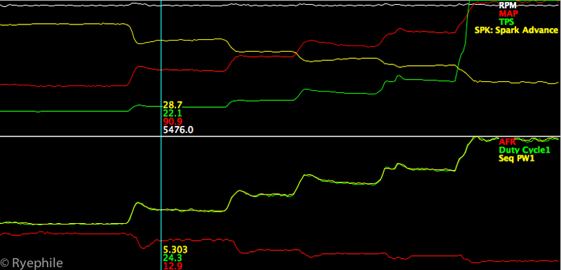
Here's a fun data excerpt from doing fixed RPM load-step testing. You can see the transitions are clean and precise. It's also a good test of thermal capacity, depending on how long you actually hold the higher loads. We were trying to maximize the Dyna-Pack's capabilities at this point while also verifying both the base VE map and the X-Tau settings made sense versus the AFR target.
 graph.jpg by Ryephile, on Flickr
graph.jpg by Ryephile, on Flickr
Reply
0
0
 05-21-2015, 09:32 AM
#106

Doubt he'll share them, since he went through all the effort of removing actual numbers from the map he posted earlier.
But can you or your tuner PLEASE chime in on at least how you went about dialing in injector timing?
This seems to be a mysterious topic around these parts, pretty much no one seems to know or comment on it.
I attempted to question the difference in injector timing maps that came with my verious megasquirts, since they all seemed very different with no rhyme or reason to the differences, and got nowhere with that.
Reply
0
0
05-21-2015, 10:38 AM
#107
Junior Member
Thread Starter
iTrader: (1)
Join Date: Jun 2014
Location: Metro Detroit
Posts: 270
Total Cats: 26
Doubt he'll share them, since he went through all the effort of removing actual numbers from the map he posted earlier.
But can you or your tuner PLEASE chime in on at least how you went about dialing in injector timing?
This seems to be a mysterious topic around these parts, pretty much no one seems to know or comment on it.
I attempted to question the difference in injector timing maps that came with my verious megasquirts, since they all seemed very different with no rhyme or reason to the differences, and got nowhere with that.
But can you or your tuner PLEASE chime in on at least how you went about dialing in injector timing?
This seems to be a mysterious topic around these parts, pretty much no one seems to know or comment on it.
I attempted to question the difference in injector timing maps that came with my verious megasquirts, since they all seemed very different with no rhyme or reason to the differences, and got nowhere with that.
The final VE map looks very similar to the one posted prior in terms of shaping. The slope through load was adjusted slightly, and also the curve shape after VE peak. This is where spending the time on a fixed-speed dyno and doing load sweeps at set RPM intervals is very helpful in pin-pointing exactly how your VE table is functioning, leaving O2 feedback and AE out of the equation is important, not trivial.
The full results of the Injection timing experiment I won't share at this point, as we discovered what appears to be a bug in the firmware, so the implementation is not as ideal as preferred. Basically, the MS3 has an issue when doing certain injection timing transitions. For now, we're running 300� BTDC for the entire map, which is not ideal for certain loads, but avoiding the firmware transition error is more important than sticking to ideals. In the end, the car has to drive perfect, so there are compromises you make to achieve that smoothness.
To elaborate further on the test itself, we chose 500 RPM intervals and held specific throttle angles, then swept injection timing and observed measured torque output. This isn't perfect as you also have to be mindful of MAP changes with torque output. At higher loads and RPMs, there was no change [WOT, for example], but at lower loads and RPMs, we were able to measure up to a 10% change in torque output at the same MAP, which is significantly more than we anticipated. Basically, an idealized injection timing map will improve lower load and RPM BSFC.
If I had 4 or 5 more engines to dispose of, then we would push the envelope further on things like AFR, ignition timing, and aggressive knock sensor tuning and feedback. As it stands now, we feel the setup will keep the reliability high, which is the primary goal.
Reply
0
0
05-21-2015, 10:44 AM
#108
Thanks for the explanation, and no worries about not posting numbers, I know they're next to useless on other cars anyway just like you said.
My car runs flawlessly, but is still on the injector timing map that DIYautotune shipped me the ecu with, and that is the only part of my tune that I have no idea what it does/should do, hence my curiosity.
I'm really liking the approach you guys are taking with the tune (good job on the dyno numbers btw) so I'm "paying attention" over here
Reply
0
0
05-21-2015, 11:07 AM
#109
Retired Mech Design Engr
iTrader: (3)
Join Date: Jan 2013
Location: Seneca, SC
Posts: 5,009
Total Cats: 856
The full results of the Injection timing experiment I won't share at this point, as we discovered what appears to be a bug in the firmware, so the implementation is not as ideal as preferred. Basically, the MS3 has an issue when doing certain injection timing transitions. For now, we're running 300� BTDC for the entire map,
At higher loads and RPMs, there was no change [WOT, for example], but at lower loads and RPMs, we were able to measure up to a 10% change in torque output at the same MAP, which is significantly more than we anticipated. Basically, an idealized injection timing map will improve lower load and RPM BSFC.
we feel the setup will keep the reliability high, which is the primary goal.
Also makes sense that Inj timing would make less difference at high loads, especially for those of us that will be running close to 100% open at max load / RPM.
Reply
0
0
05-21-2015, 11:14 AM
#110
Junior Member
Thread Starter
iTrader: (1)
Join Date: Jun 2014
Location: Metro Detroit
Posts: 270
Total Cats: 26
I definitely appreciate the compliment. For arghx7 it's been a fun diversion from his OEM work, and I'm thankful he's willing to share his incredible wisdom. We wrote out a specific game-plan prior to going to the dyno, so our tests were methodical and organized. The tune foundation was sorted first [fuel], then ignition timing, then injection timing, then X-Tau. All the data-logs and tune revisions are labeled so we can look back on them and understand what they're for.
I'll say that if you're happy with how the car drives, that's the most important facet. It's quite difficult to do any sort of injection timing tuning on the street, and in the big picture it's port injection, so it's a fairly small adjustment anyway.
In a few weeks I'll have one more major update for the car!
Reply
0
0
05-21-2015, 12:01 PM
#111
Junior Member

Join Date: May 2015
Posts: 86
Total Cats: 11
A few brief comments:
Only loading dynos actually measure torque. So you can't hold speed and load (sort-of, by throttle angle) and sweep parameters if you are using a basic dynojet, as they measure acceleration during transient pulls and back calculate torque and power.
The injection timing we are using is fixed end-of-injection, which can be set under the sequential fuel injection settings. That means the start of injection is constantly changing according to the duty cycle.
Remember that duty cycle = 720 crank angle degrees - injection duration in crank angle degrees. If I'm at 50% duty, my injection duration should be ~360 degrees, with start of injection back calculated from the end of injection time. That's assuming steady state operation with no X-tau etc (that stuff complicates it a lot). If I set a fixed value to an entire map, the injection timing is still changing all the time. If I have an EOI of 300 degrees BTDC firing and 20% duty, my duration is 144 degrees, so my SOI is 444 degrees BTDC.
300 deg btdc results in the injection event ending while the intake valve is still opening ("open valve injection"). You can sweep EOI earlier and later and see what happens. Without an emissions bench (to look at mixing according to HC ppm, CO%, and O2%) or combustion indication (to look at IMEP, combustion stability, etc), you can can only go on subjective assessement (did the engine run smoother at idle) or measured torque on a loading dyno.
The shape of the VE table is important, and in a way more important than the numbers themselves. If you are looking horizontally across the map (as rpm changes), it should roughly follow the VE curve according to intake valve closing timing. Later intake valve closing timing = VE peak later. With a fixed cam engine like this it's easy. With variable valve timing (cam phasing or lift change) the complexity increases drastically.
If you are looking vertically across the table, the shape of the curve is proportional to the airflow addded with boost (1st derivative of the curve), with enrichment baked into the rate of change between cells (2nd derivative of the curve).
As for spark timing, the closer you are to where it needs to be, the less effect the changes will make. If you sweep timing a few degrees and only see a couple hp difference, within test-to-test variation, then you're timing is in the right range. It's probably not adviseable to advance it just to squeeze a few hp out of it.
For boost control, the mechanical characteristics of the system need to be right. You have to resolve spring pressure, solenoid plumbing, preload of internal wastegate, etc. You need that good foundation before you set duty cycle tables, controller gains, and (hopefully if MS adds the code) air temp and baro compensation to the feedforward portion.
Reply
3
3
05-21-2015, 04:45 PM
#112
Junior Member
Thread Starter
iTrader: (1)
Join Date: Jun 2014
Location: Metro Detroit
Posts: 270
Total Cats: 26
^^^Thanks for chiming in!
In other news, Autoblog posted a little video from the ND reveal on Woodward, and at 3:06 they did a shot of my Miata's engine bay. Sweet.
In other news, Autoblog posted a little video from the ND reveal on Woodward, and at 3:06 they did a shot of my Miata's engine bay. Sweet.
Reply
0
0
06-10-2015, 12:26 AM
#113
Junior Member
Thread Starter
iTrader: (1)
Join Date: Jun 2014
Location: Metro Detroit
Posts: 270
Total Cats: 26
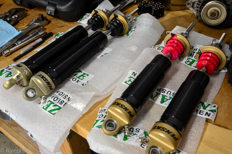
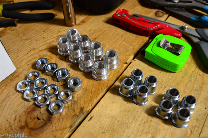
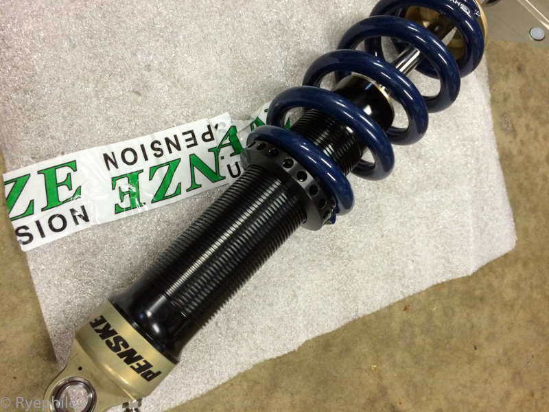
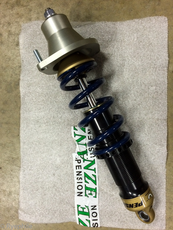
One of the last "install" updates, and it's a big one. Anze Suspension bespoke Penske setup. These guys are 1st class to deal with. Their wisdom and experience is abundant and their professionalism is top-notch. While I've been familiar with Anze for well over a decade, it was my first actual project with them and I'm very pleased to be part of their family now.
 RYE_0235.jpg by Ryephile, on Flickr
 RYE_0244.jpg by Ryephile, on Flickr
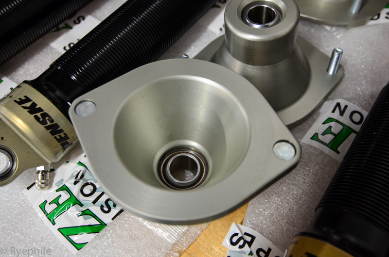
The dampers are based on the 7500 DA's but with proprietary Anze valves and valving. Stroke and positioning is to my spec. Total stroke is more than sufficient for the new spring rates, which rely on Anze and V2 Motorsports's huge knowledge database. Upper mounting hats are billet aluminum with serviceable spherical bearings.
Even the mounting hardware is jewelry:
 RYE_0246.jpg by Ryephile, on Flickr
 IMG_5743.jpg by Ryephile, on Flickr
 IMG_5755.jpg by Ryephile, on Flickr
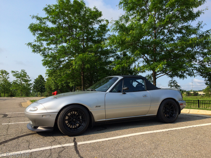
The car is roughed in for corner balance at the moment, but it's clear the Penske's are worth every penny. They ride smooth, have fantastic quick weight transfer, absorb classic Detroit "roads", and stay composed at all times just like a legit quality damper should. It'll get setup fine tuned next week, and then finally it'll be track time!
 IMG_5792.jpg by Ryephile, on Flickr
RYE_0235.jpg by Ryephile, on FlickrRYE_0244.jpg by Ryephile, on FlickrThe dampers are based on the 7500 DA's but with proprietary Anze valves and valving. Stroke and positioning is to my spec. Total stroke is more than sufficient for the new spring rates, which rely on Anze and V2 Motorsports's huge knowledge database. Upper mounting hats are billet aluminum with serviceable spherical bearings.
Even the mounting hardware is jewelry:
RYE_0246.jpg by Ryephile, on FlickrIMG_5743.jpg by Ryephile, on FlickrIMG_5755.jpg by Ryephile, on FlickrThe car is roughed in for corner balance at the moment, but it's clear the Penske's are worth every penny. They ride smooth, have fantastic quick weight transfer, absorb classic Detroit "roads", and stay composed at all times just like a legit quality damper should. It'll get setup fine tuned next week, and then finally it'll be track time!
IMG_5792.jpg by Ryephile, on Flickr
Reply
1
1

 06-19-2015, 04:35 PM
#115
Junior Member
Thread Starter
iTrader: (1)
Join Date: Jun 2014
Location: Metro Detroit
Posts: 270
Total Cats: 26
The car spent a few days at the race-shop spa.
*ES poly bushings in all suspension arms
*ES poly diff bushings, the hard way. Pressing out the stock bushings fractured the housing, so I now have a very pretty brand new diff housing in the car.
*Corner balanced and aligned. Going with a hybrid concept, blending V2's SM experience with my half-street half-track no rule-book application. We'll see how the first track day goes, lots of trailblazing to sort through yet.
I was surprised and/or relieved to see the car isn't a total armored tank on the scales. 2,218 lbs without me but with >1/2 tank of fuel. That's only 2 pounds more than the advertised weight from the 1992 Miata brochure. Not bad for 10 pounds of **** in a 5 pound bag.
Reply
0
0


 06-23-2015, 06:13 PM
#118
Elite Member
iTrader: (1)

Join Date: Jun 2006
Location: Warrington/Birmingham
Posts: 2,642
Total Cats: 42
Can I ask the reason your using x-Tau over EAE?
I can't tune either for ****, I was just wondering why you went for x-tau. I was under the -possibly misguided - impression that EAE is a superior wall wetting algorithm.
I can't tune either for ****, I was just wondering why you went for x-tau. I was under the -possibly misguided - impression that EAE is a superior wall wetting algorithm.
Reply
0
0
06-23-2015, 07:21 PM
#119
Junior Member
Thread Starter
iTrader: (1)
Join Date: Jun 2014
Location: Metro Detroit
Posts: 270
Total Cats: 26
It appears the MS guys wrote EAE without fully understanding why it's used [originally as a hydrocarbon emission countermeasure] and it ends up being a tip-in band-aid with a steady-state calculation, whereas looking at their x-tau presentation, the implementation is much closer to a model based delta MAP.
In any case, whatever ends up working for your setup is what's important. X-Tau works brilliant in my application.
If you can't tune either, it's very likely then your VE map isn't correctly tuned. Without that correct no amount of AE tuning will ever work right. You should be able to drive the car with just the VE map and no AFR feedback or AE turned on and it should drive perfect except for bigger tip-ins and tip-outs. Casual tip-in's don't usually need AE.
Reply
0
0
06-24-2015, 02:43 AM
#120
Junior Member
Join Date: May 2015
Posts: 86
Total Cats: 11
I will chime in and say that when I look at EAE and X-Tau and compare it to OEM level code I have used or been exposed to, EAE logic is very much like the hydrocarbon countermeasures. You can tell by the way the maps are speed load based, rather than with a time component for transient operation.
When you're trying to pass emissions on a port injected engine you typically use an unburned fuel model, which is more like the EAE. The transient fuel calculation has components based on time. That's an oversimplified answer to a complicated matter. I've got some diagrams I can dig up that might help a little.
When you're trying to pass emissions on a port injected engine you typically use an unburned fuel model, which is more like the EAE. The transient fuel calculation has components based on time. That's an oversimplified answer to a complicated matter. I've got some diagrams I can dig up that might help a little.
Reply
0
0


