COP Thread


 03-14-2011, 05:24 PM
#1383

My question to Zaphod was regarding this:
Originally Posted by Zaphod
"as an NB user I got 2 line with ground and +12V separated always for two cylinders. "

Reply
 0
0

0
03-15-2011, 03:02 AM
#1384
Elite Member

Join Date: Mar 2006
Location: Schwarzenberg, Germany
Posts: 1,553
Total Cats: 101
@ Barbycar - there is nothing you have to worry about.
Let me explain -
I got separate lines (ground and +12V) for cylinders 1+3 and for 2+4 (I am not really sure - it could also be 1+4 and 2+3)
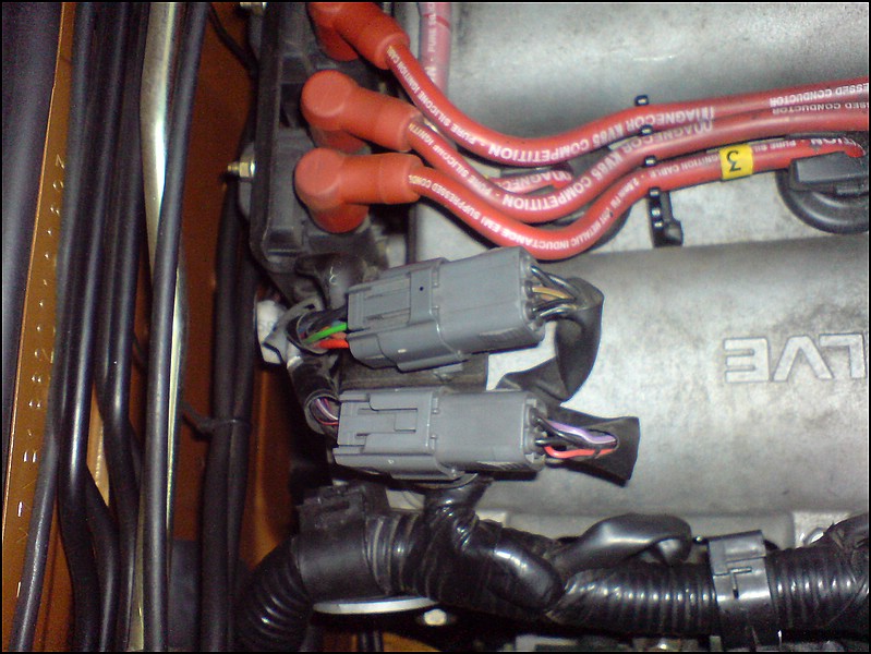
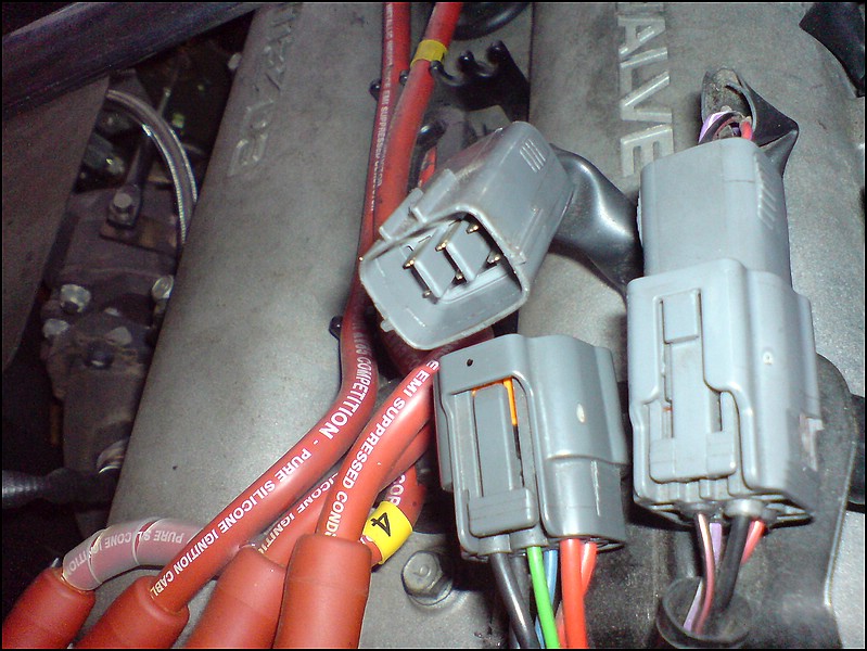
My (Euro 1,6 NB) has an connector at the back of the valve cover, which gives my 2x ground, 2x +12V and the two trigger lines.
This seems to be some specialty of the 1,6 NB (which is not known in the US). The lines do come from the same source at the end.
I made my Cop conversion plug and play this way.
Now I have to put one cap in each of the lines.
Let me explain -
I got separate lines (ground and +12V) for cylinders 1+3 and for 2+4 (I am not really sure - it could also be 1+4 and 2+3)
My (Euro 1,6 NB) has an connector at the back of the valve cover, which gives my 2x ground, 2x +12V and the two trigger lines.
This seems to be some specialty of the 1,6 NB (which is not known in the US). The lines do come from the same source at the end.
I made my Cop conversion plug and play this way.
Now I have to put one cap in each of the lines.
Reply
0
0
03-15-2011, 10:08 AM
#1385
@ Barbycar - there is nothing you have to worry about.
Let me explain -
I got separate lines (ground and +12V) for cylinders 1+3 and for 2+4 (I am not really sure - it could also be 1+4 and 2+3)
My (Euro 1,6 NB) has an connector at the back of the valve cover, which gives my 2x ground, 2x +12V and the two trigger lines.
This seems to be some specialty of the 1,6 NB (which is not known in the US). The lines do come from the same source at the end.
I made my Cop conversion plug and play this way.
Now I have to put one cap in each of the lines.
Reply
0
0


 03-22-2011, 04:40 AM
#1387
Junior Member

Join Date: Mar 2011
Location: Guildford, UK
Posts: 163
Total Cats: 0
Absolutely brilliant thread.
I think this is worth doing even for nat/asp applications, along with sequential injection and a MS I reckon you might be able to save 5mpg. That's up to 50 extra miles per tank. Petrol in the UK is about $2.16 per litre or $8.16 per US Gallon.
OK, where's the 70 page thread on injection.
I think this is worth doing even for nat/asp applications, along with sequential injection and a MS I reckon you might be able to save 5mpg. That's up to 50 extra miles per tank. Petrol in the UK is about $2.16 per litre or $8.16 per US Gallon.
OK, where's the 70 page thread on injection.
Reply
0
0
03-22-2011, 05:32 AM
#1388
Elite Member
iTrader: (1)

Join Date: Jun 2006
Location: Warrington/Birmingham
Posts: 2,642
Total Cats: 42
[QUOTE=Freaky Roadster;704733]Absolutely brilliant thread.
I think this is worth doing even for nat/asp applications, along with sequential injection and a MS I reckon you might be able to save 5mpg.QUOTE]
I'll believe it when I see it. aka, not a chance.
It's a fun project to do though.
I think this is worth doing even for nat/asp applications, along with sequential injection and a MS I reckon you might be able to save 5mpg.QUOTE]
I'll believe it when I see it. aka, not a chance.
It's a fun project to do though.
Reply
0
0
 Oh well, maybe not 5mpg then
 and might convince the Mrs on the outlay
03-27-2011, 11:58 AM
and might convince the Mrs on the outlay
03-27-2011, 11:58 AM
#1390

I've read 33 pages in, there's quite a bit of information here. Glad to see brain posted a howto, it would be a nightmare to sift through all this and retain everything 
Question I have though; Do I need a capacitor for this setup, or is it strictly an optional thing? I can't find the mention of it in the thread so far.. I assume also that I can just splice into the harness before the connector if I don't want to peel off my ignitor connector?
Edit- Edited for clarity, and because I read deeper into the thread.
Last edited by Der_Idiot; 03-28-2011 at 02:00 PM.
Reply
0
0
03-27-2011, 06:53 PM
#1391
Junior Member
Join Date: Mar 2011
Location: Guildford, UK
Posts: 163
Total Cats: 0
Well, I've had a poke under the hood and it looks like mine is the "newer" 1.8, the difference is that the TACH signal comes from the CAS and not the coils so only 3 wires to each COP. That's GND, +12v, Triggers.
Reply
0
0
03-29-2011, 02:21 PM
#1392

Ok, I got my COPs ready to go back on the motor. 
I had a hold down consisting of a single aluminum rod going along the top of all the coils. The rod itself was held at the ends by small brackets secured by the end/center valve cover screws.
My son lost the pieces to the above so now I can make the same or something else...
Have you guys tried like 4 shallow countersunk holes on the aluminum with the head of 4 screws JB welded into it. It would serve as studs for the coils ( ? )
OR am I better off with the old aluminum plate on the valley of the valve cover with 4 holes ? I don't think I can easily source the aluminum plate and then the correct size hole saw.
Reply
0
0
03-29-2011, 03:27 PM
#1394
Thanks for the heads up.
My hold down system was stupid in its elegance or something like that. Mainly, the aluminum rod flexed a bit so while the end coils were held down tightly, the ones in the middle were a little loose.
I think a .250 carbon fibre rod that I have will work....
If I do try the JB weld thing I'll shoot for screws with very broad flat heads and shallow indentations on the valve cover.
Reply
0
0
04-01-2011, 07:05 PM
#1395
Does it matter much what the size of the cap is, as long as it's 10k uf? I'm having trouble sourcing a capacitor for this application, and I have everything else I need. How much of a benefit am I looking at here?
Edit; I found these on Amazon, they look like they might work for this..
Edit; I found these on Amazon, they look like they might work for this..
Last edited by Der_Idiot; 04-01-2011 at 07:34 PM.
Reply
0
0
04-01-2011, 09:06 PM
#1396
Does it matter much what the size of the cap is, as long as it's 10k uf? I'm having trouble sourcing a capacitor for this application, and I have everything else I need. How much of a benefit am I looking at here?
Edit; I found these on Amazon, they look like they might work for this..
Edit; I found these on Amazon, they look like they might work for this..
You don't need a single 10'000 uf capacitor. You can get two 4700uf and connect them in paralell ...meaning the two caps go together postive to positive and negative to negative and they become electically like a larger capacitot.
Reply
0
0
 04-05-2011, 04:10 PM
#1398
I did my test install today and it fired up first time - Yay.
A question to the electronics gurus - I built a dwell reducer (running stock ECU on my 2000) using Jason's circuit design http://forum.miata.net/vb/showpost.p...7&postcount=41 but I translated it onto strip circuit card. http://en.wikipedia.org/wiki/Stripboard. Since the car started and ran just fine, can I assume that the circuit is working and therefore dwell reduction is occurring?
A question to the electronics gurus - I built a dwell reducer (running stock ECU on my 2000) using Jason's circuit design http://forum.miata.net/vb/showpost.p...7&postcount=41 but I translated it onto strip circuit card. http://en.wikipedia.org/wiki/Stripboard. Since the car started and ran just fine, can I assume that the circuit is working and therefore dwell reduction is occurring?
Last edited by BarbyCar; 04-05-2011 at 04:32 PM.
Reply
0
0


