DIY gauge cluster with Maxigauge
 05-03-2012, 09:38 AM
#21
Elite Member
Thread Starter

Join Date: Mar 2006
Location: Schwarzenberg, Germany
Posts: 1,553
Total Cats: 101
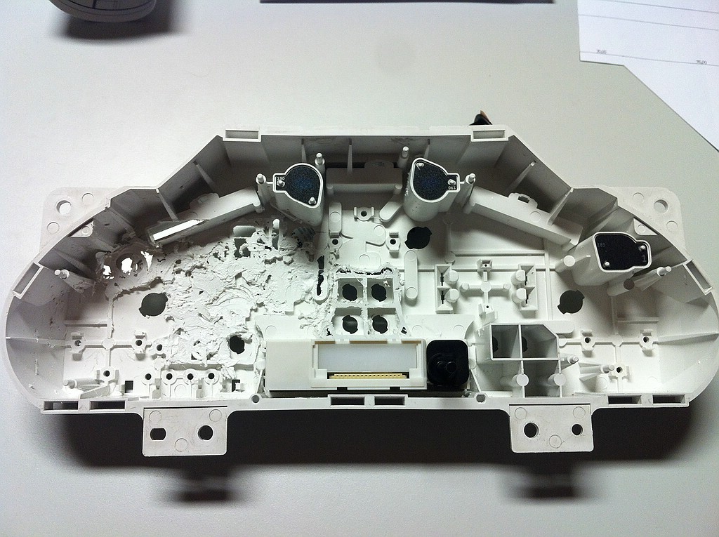
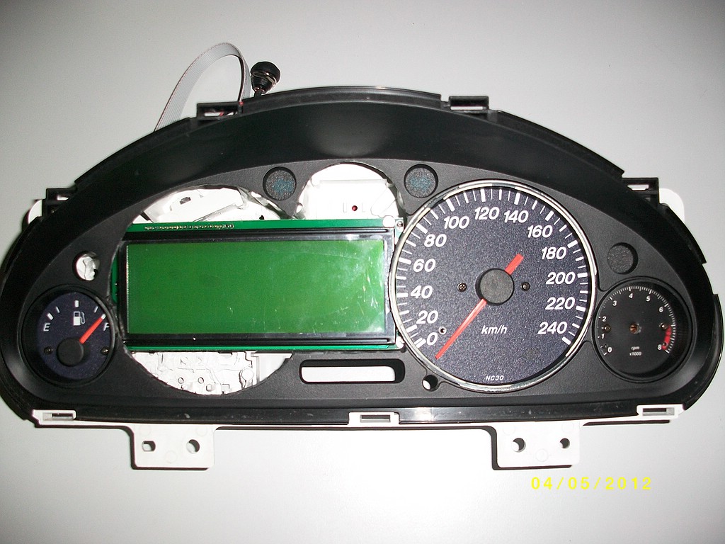
Slow progress - I got some unforeseen space problems in the gauge cluster...
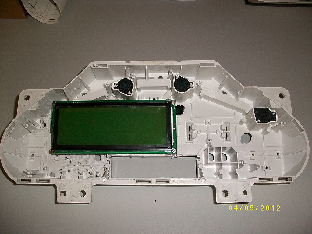
Making room:
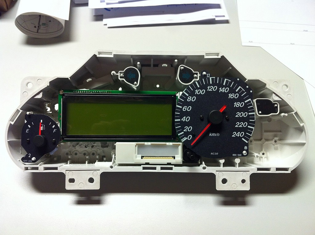
With the first gauges and the Maxigauge in place:
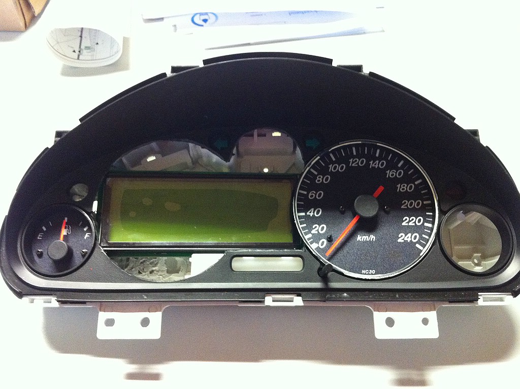
With the cut and mounted bezel
Now I have to make mounts for the Maxigauge and wire everything up.
Making room:
With the first gauges and the Maxigauge in place:
With the cut and mounted bezel
Now I have to make mounts for the Maxigauge and wire everything up.

Reply
 0
0

0
 05-04-2012, 10:31 AM
#24
Elite Member
Thread Starter
Join Date: Mar 2006
Location: Schwarzenberg, Germany
Posts: 1,553
Total Cats: 101
Lets go on ...
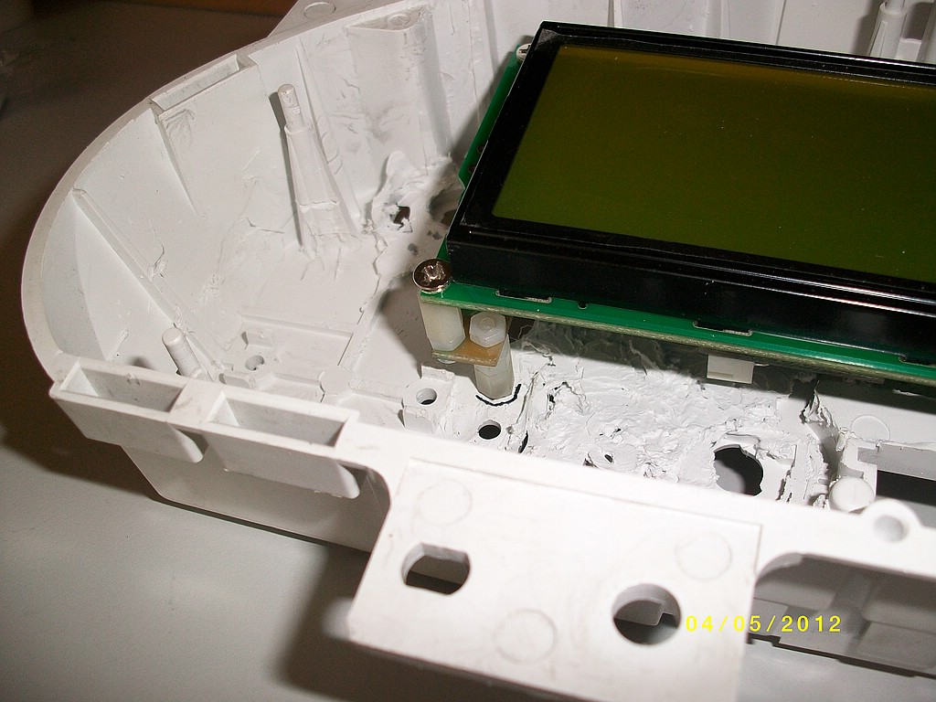
Mounted the Maxigauge on standoffs at the correct height
Made out of some old plastic leftovers, cut to length and threads into both sides
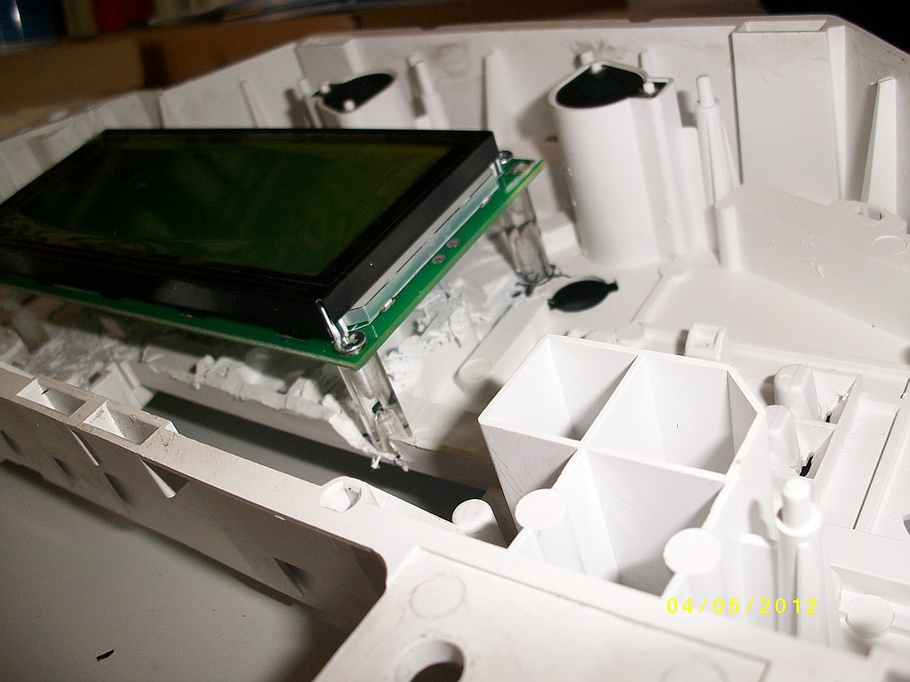
Had to make some adjustments to the Maxigauge, and get a bit creative
Mounted in place and first test of the gauge - powered by my Jimstim...
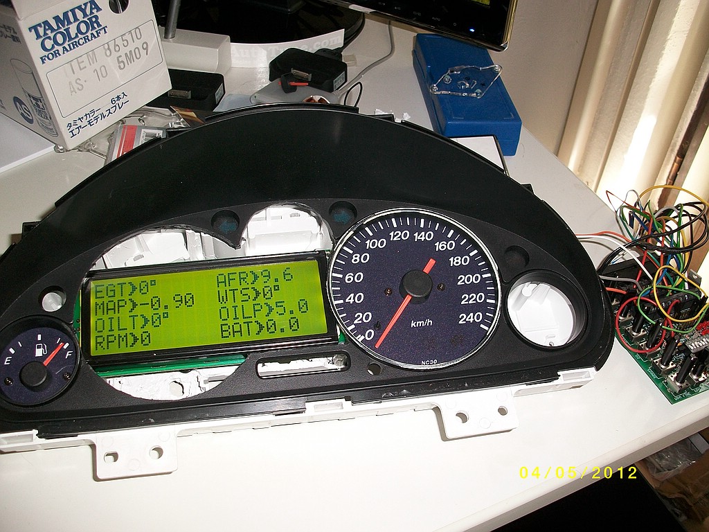
(without flash)
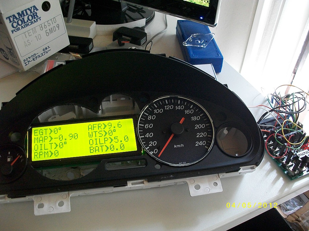
Attached my old RPM gauge to the small gauge face - and put it in place
Mounted the Maxigauge on standoffs at the correct height
Made out of some old plastic leftovers, cut to length and threads into both sides
Had to make some adjustments to the Maxigauge, and get a bit creative
Mounted in place and first test of the gauge - powered by my Jimstim...
(without flash)
Attached my old RPM gauge to the small gauge face - and put it in place
Reply
1
1
05-04-2012, 11:51 AM
#25
Junior Member

Join Date: Mar 2012
Location: Portugal
Posts: 200
Total Cats: -12
Looking so awesome! I'm thoroughly jealous!
Look, can I ask you a favour? Since you have that NB cluster out of the car, can you take a photo of the back circuitry for me? I'm curious to know what is involved in making it compatible with an NA!
Look, can I ask you a favour? Since you have that NB cluster out of the car, can you take a photo of the back circuitry for me? I'm curious to know what is involved in making it compatible with an NA!
Reply
0
0


 05-04-2012, 03:28 PM
#30
Elite Member
Thread Starter
Join Date: Mar 2006
Location: Schwarzenberg, Germany
Posts: 1,553
Total Cats: 101
As I stated in one of the earlier posts, I would have loved to make a big tach + small speedo, but the T�V (Association for technical inspection) wants to see the car every 2 years to check for technical correctness.
@RyanLewo - Sorry but no, this is quite a handful of work, and I run a Engineering offce as a civil engineer, have two kids and so on...
@revlimiter - I have to give the credit to you, otherwise I wouldn't have known how to make the gauge face for the small tach...
@RyanLewo - Sorry but no, this is quite a handful of work, and I run a Engineering offce as a civil engineer, have two kids and so on...
@revlimiter - I have to give the credit to you, otherwise I wouldn't have known how to make the gauge face for the small tach...
Reply
0
0
05-16-2012, 04:27 AM
#31
Elite Member
Thread Starter
Join Date: Mar 2006
Location: Schwarzenberg, Germany
Posts: 1,553
Total Cats: 101
A bit more wiring is done,
as I want this whole thing to be plug and play - this is a bit more complex...
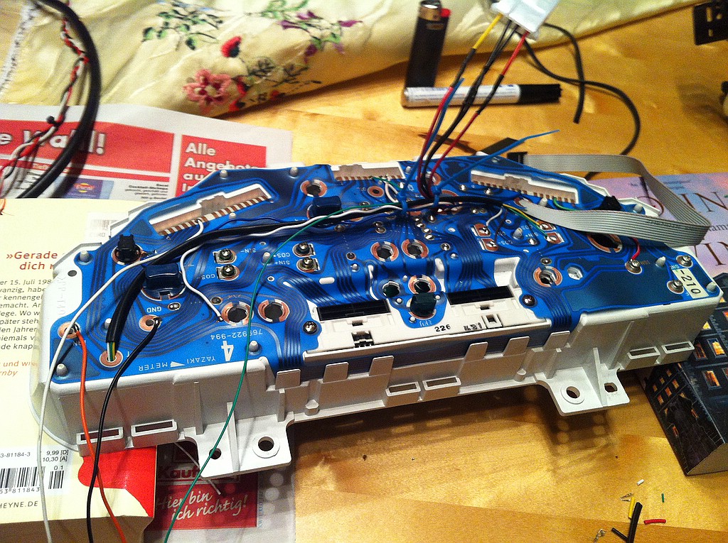
I relocated some of the signal lights - highbeam, abs, handbrake...
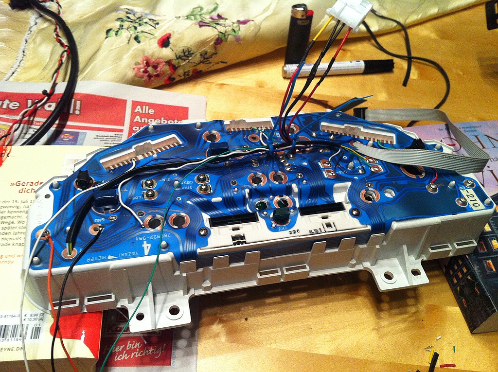
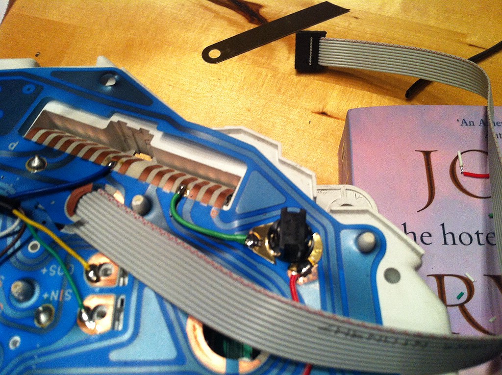
This is the wiring for the relocated tach gauge
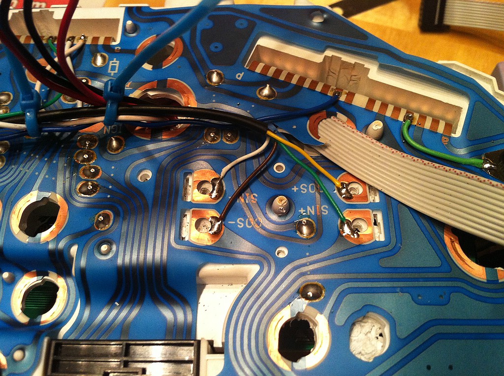
It's easy to solder on the copper pads of the OEM circuit. Some of the old traces have to be cut...
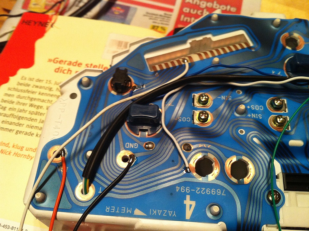
the cluster is actually in the car, but I have to redo some of the wiring and change the gauge bezel...
as I want this whole thing to be plug and play - this is a bit more complex...
I relocated some of the signal lights - highbeam, abs, handbrake...
This is the wiring for the relocated tach gauge
It's easy to solder on the copper pads of the OEM circuit. Some of the old traces have to be cut...
the cluster is actually in the car, but I have to redo some of the wiring and change the gauge bezel...
Reply
0
0
 05-31-2012, 03:25 AM
#34
Elite Member
Thread Starter
Join Date: Mar 2006
Location: Schwarzenberg, Germany
Posts: 1,553
Total Cats: 101
All done and finished...
The finish of the surface of the cluster is not perfect, but it's o.k. for the moment (might redo this over the wintertime)
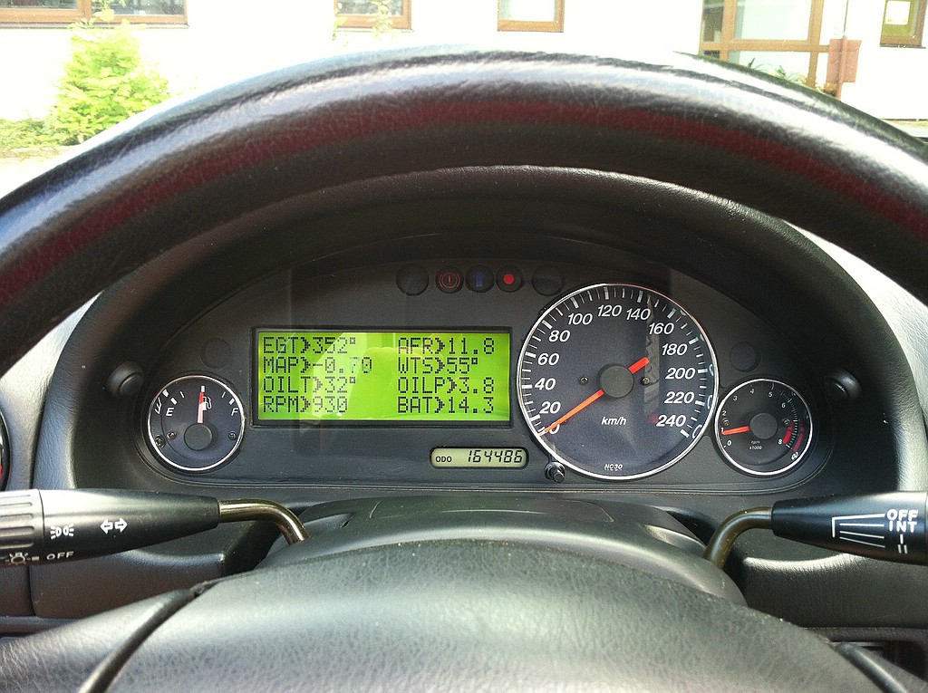
The 3 indicators in the middle are handbrake (left), shiftlight (middle), warning from Maxigauge (right).
You can see the two buttons for switching through the menus of the Maxigauge on the left and right side of the cluster hood.
The finish of the surface of the cluster is not perfect, but it's o.k. for the moment (might redo this over the wintertime)
The 3 indicators in the middle are handbrake (left), shiftlight (middle), warning from Maxigauge (right).
You can see the two buttons for switching through the menus of the Maxigauge on the left and right side of the cluster hood.
Reply
2
2


 Sweet, looks fantastic.


