DIY Turbo Discussion greddy on a 1.8? homebrew kit?

Electronic Boost control from unused wire in loom

Thread Tools
 
Search this Thread
 
Old 02-12-2016, 06:42 PM
  #21  
Elite Member
iTrader: (3)
 
deezums's Avatar
 
Join Date: May 2014
Location: Kansas
Posts: 3,146
Total Cats: 201
Default

I disagree, why would you purposefully make EBC have to work harder? When I'm in boost I only see maybe 5-10% difference between the start of a pull and the end. If I was sourcing on the hotside, that range would be much larger.

Plus, I just turn mine off if I want low boost. It's pretty important it's on the coldside for that.
deezums is offline  
Old 02-12-2016, 06:44 PM
  #22  
SADFab Destructive Testing Engineer
iTrader: (5)
 
aidandj's Avatar
 
Join Date: Apr 2014
Location: Beaverton, USA
Posts: 18,642
Total Cats: 1,866
Default

Because you aren't actually making EBC work harder.

EBC is calculating duty cycle based off of your MAP signal, which comes from the intake manifold, as cold side as it gets. It doesn't matter how much boost the wastegate is seeing because EBC is controlling that.
aidandj is offline  
Old 02-12-2016, 06:47 PM
  #23  
Elite Member
iTrader: (3)
 
deezums's Avatar
 
Join Date: May 2014
Location: Kansas
Posts: 3,146
Total Cats: 201
Default

Yes, you are making EBC work harder.

Instead of just having to increase/decease boost as necessary to match engine requirements, you are now having EBC deal with pressure drop of the engine and intercooler both.

It can and will do it, but it's not right.
deezums is offline  
Old 02-12-2016, 06:49 PM
  #24  
SADFab Destructive Testing Engineer
iTrader: (5)
 
aidandj's Avatar
 
Join Date: Apr 2014
Location: Beaverton, USA
Posts: 18,642
Total Cats: 1,866
Default

Nope. Once you have tuned it (initial value or bias table) then the pressure drop of your intake piping is already taken into account.

All EBC does is control what the wastegate sees. So EBC can make it see whatever it wants, no matter what the boost source is.
aidandj is offline  
Old 02-12-2016, 06:53 PM
  #25  
Senior Member
Thread Starter
iTrader: (5)
 
90civichhb's Avatar
 
Join Date: Oct 2014
Posts: 542
Total Cats: 36
Default

Originally Posted by aidandj
I used the maf wire i believe
So I don't see a maf pin on my board, but I do see a MAP pin. Do you know what wire that corresponds with on the AFM plug?
90civichhb is offline  
Old 02-12-2016, 06:54 PM
  #26  
SADFab Destructive Testing Engineer
iTrader: (5)
 
aidandj's Avatar
 
Join Date: Apr 2014
Location: Beaverton, USA
Posts: 18,642
Total Cats: 1,866
Default

I don't know **** about DIYPNPs
aidandj is offline  
Old 02-12-2016, 06:55 PM
  #27  
Senior Member
Thread Starter
iTrader: (5)
 
90civichhb's Avatar
 
Join Date: Oct 2014
Posts: 542
Total Cats: 36
Default

Well hawt damn, back on the grind.
90civichhb is offline  
Old 02-12-2016, 07:32 PM
  #28  
Senior Member
Thread Starter
iTrader: (5)
 
90civichhb's Avatar
 
Join Date: Oct 2014
Posts: 542
Total Cats: 36
Default

So according to this diagram the WOT switch on the 90-93 is 2L. Does this 2L also correspond with the 2L pin on the expansion board?

Attached Thumbnails Electronic Boost control from unused wire in loom-mx5_ecu_pinouts.jpg  
90civichhb is offline  
Old 02-12-2016, 07:46 PM
  #29  
Elite Member
iTrader: (3)
 
deezums's Avatar
 
Join Date: May 2014
Location: Kansas
Posts: 3,146
Total Cats: 201
Default

No, any time you see a 2, you need to make it a 4.

Unless I'm mistaken, the pins numbered #2 and #3 are for other 1.8 miata. No plug on your 1.6 harness will fit anywhere else, the ECU plugs should be in #1 and #4 spots...
deezums is offline  
Old 02-12-2016, 07:54 PM
  #30  
Senior Member
Thread Starter
iTrader: (5)
 
90civichhb's Avatar
 
Join Date: Oct 2014
Posts: 542
Total Cats: 36
Default

Originally Posted by deezums
No, any time you see a 2, you need to make it a 4.

Unless I'm mistaken, the pins numbered #2 and #3 are for other 1.8 miata. No plug on your 1.6 harness will fit anywhere else, the ECU plugs should be in #1 and #4 spots...
I see, so 4L should be the pin I use with Megasquirt? I guess that is why you said 4x earlier. Just making sure it wasn't a coincidence.
90civichhb is offline  
Old 02-12-2016, 07:59 PM
  #31  
Senior Member
Thread Starter
iTrader: (5)
 
90civichhb's Avatar
 
Join Date: Oct 2014
Posts: 542
Total Cats: 36
Default

Nevermind, just pulled the MS apart and I am using 4L for my vTPS.
90civichhb is offline  
Old 02-12-2016, 08:04 PM
  #32  
Elite Member
iTrader: (3)
 
deezums's Avatar
 
Join Date: May 2014
Location: Kansas
Posts: 3,146
Total Cats: 201
Default

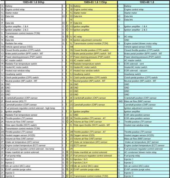
Yep, see how all the jumpers are to 1 or 4 on this 1.6 assembly chart? DIY broke the page, so this is cache and looks funny. If you compare this to your picture and line up other things like spark outs and injectors it will all make sense.

https://webcache.googleusercontent.c...&ct=clnk&gl=us
deezums is offline  
Old 02-12-2016, 08:20 PM
  #33  
Senior Member
Thread Starter
iTrader: (5)
 
90civichhb's Avatar
 
Join Date: Oct 2014
Posts: 542
Total Cats: 36
Default

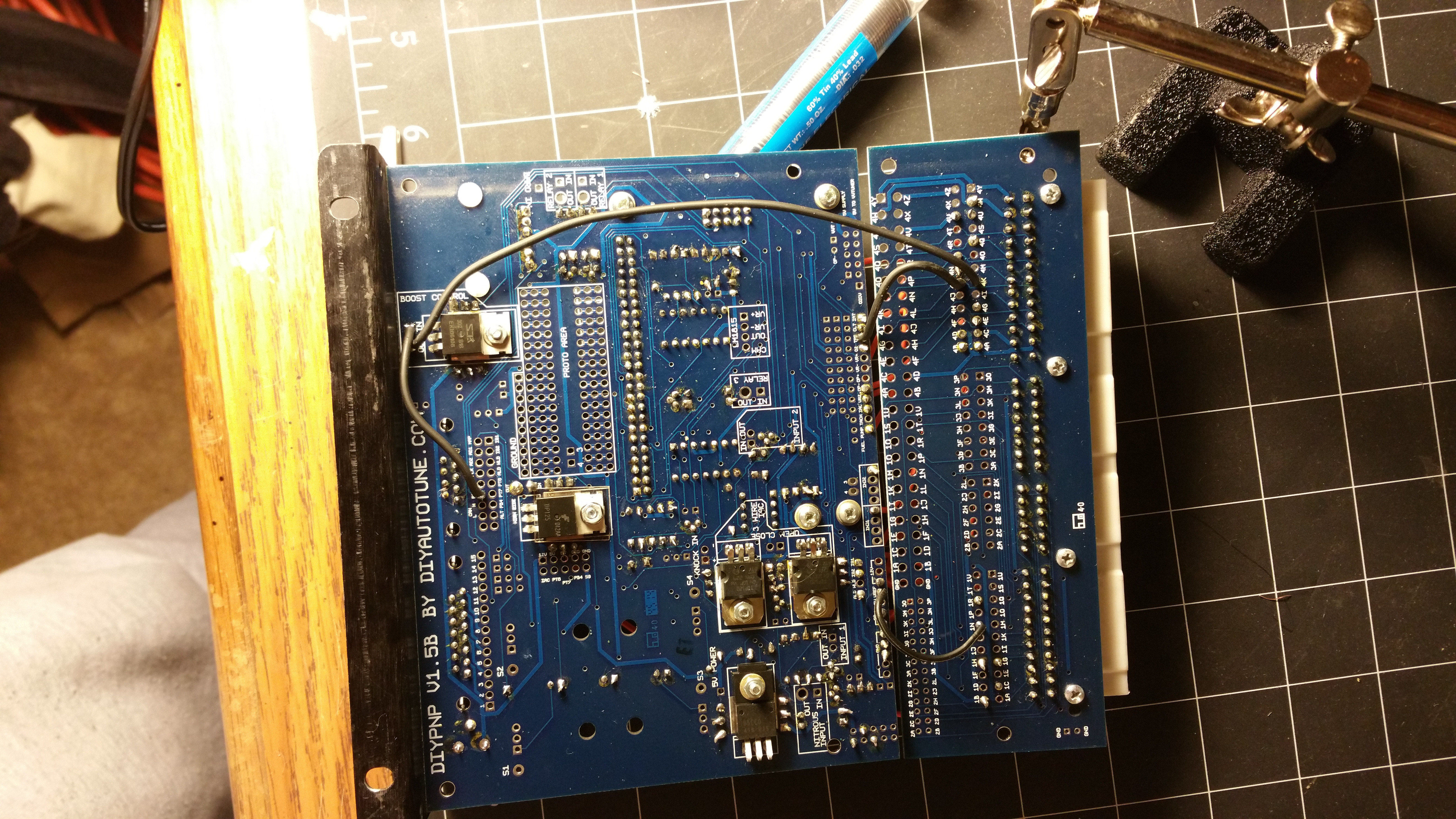
Thanks, this does make it much easier to track each wire, but some of the wires are not mentioned on the DIY assembly chart. But my harness still has them, do these unmentioned wires still correspond in the same alphanumeric fashion?

Thanks for all your help so far. I'll be putting a video together of this process and would really like to get it right so I don't put out any false information when I start to film it.
90civichhb is offline  
Old 02-12-2016, 08:24 PM
  #34  
Elite Member
iTrader: (3)
 
deezums's Avatar
 
Join Date: May 2014
Location: Kansas
Posts: 3,146
Total Cats: 201
Default

Yep, that's how you find unused wires, or at least a starting point of it all.
deezums is offline  
Old 02-12-2016, 08:28 PM
  #35  
Senior Member
Thread Starter
iTrader: (5)
 
90civichhb's Avatar
 
Join Date: Oct 2014
Posts: 542
Total Cats: 36
Default

Awesome, thanks for all the help. I'll install it all tomorrow, looking forward to seeing how it turns out.
90civichhb is offline  
Old 02-12-2016, 09:45 PM
  #36  
Senior Member
Thread Starter
iTrader: (5)
 
90civichhb's Avatar
 
Join Date: Oct 2014
Posts: 542
Total Cats: 36
Default

So now that I have everything wired in how can I now find the wires in the car?


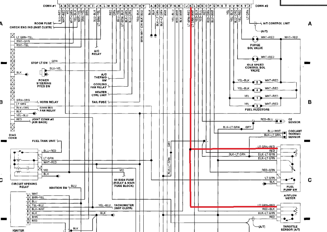
So when I look at this wiring diagram under CONN#2 I see that the K wire goes to the AFM but it also goes to the Throttle sensor. Will this be a problem when I install the EBC? Assuming that the LT GRN-RED wire is the correct one.


Attached Thumbnails Electronic Boost control from unused wire in loom-hqqmb14.jpg   Electronic Boost control from unused wire in loom-y2sngb9.jpg  
90civichhb is offline  
Old 02-12-2016, 11:04 PM
  #37  
Elite Member
iTrader: (3)
 
deezums's Avatar
 
Join Date: May 2014
Location: Kansas
Posts: 3,146
Total Cats: 201
Default

That used to be a 5v reference signal for the tps and air meter. You'll want that for a vtps mod.
deezums is offline  
Old 02-12-2016, 11:17 PM
  #38  
Senior Member
Thread Starter
iTrader: (5)
 
90civichhb's Avatar
 
Join Date: Oct 2014
Posts: 542
Total Cats: 36
Default

Then I don't understand how people are using the AFM wiring with a VTPS. With an IAT installed you don't have options.
90civichhb is offline  
Old 02-13-2016, 12:45 AM
  #39  
Junior Member
 
Barton's Avatar
 
Join Date: Jun 2015
Location: VIC, Australia
Posts: 182
Total Cats: 57
Default

The 1.6 has a few pins that go back to the ECU that you could use for the boost solenoid.

AFM Connector Pin
1 4P
2 4O
3 SG
4 4K
5 GND
6 GND
7 Fuel pump trigger

You can double check with a multimeter.

Could also use the purge solenoid wiring on 4X or the power steering switch wire on 1P.
Barton is offline  
Old 02-13-2016, 02:49 AM
  #40  
Elite Member
 
codrus's Avatar
 
Join Date: Mar 2007
Location: Santa Clara, CA
Posts: 5,165
Total Cats: 855
Default

Originally Posted by aidandj
Nope. Once you have tuned it (initial value or bias table) then the pressure drop of your intake piping is already taken into account.

All EBC does is control what the wastegate sees. So EBC can make it see whatever it wants, no matter what the boost source is.
While this is true, one of the things I like about EBC is that it's easy to flip it to a low boost setting by installing a switch to cut power to the solenoid, and at that point you'll want the clean boost signal source.

As for wiring, I hate hacking up the factory harness so I tend to use unused pins and run new wires for things like this.

--Ian
codrus is offline  


Quick Reply: Electronic Boost control from unused wire in loom


All times are GMT -4. The time now is 07:33 AM.