Late model 1.8 guys - diagram your oil feed setup
 05-08-2010, 03:59 PM
#1
Want fries with that?
Thread Starter
iTrader: (3)

Join Date: Oct 2009
Location: Twin Cities, Minnesota
Posts: 2,011
Total Cats: 2
I'm having the most frustratingly ridiculous time trying to get my oil feed in. Here's what I'm doing:
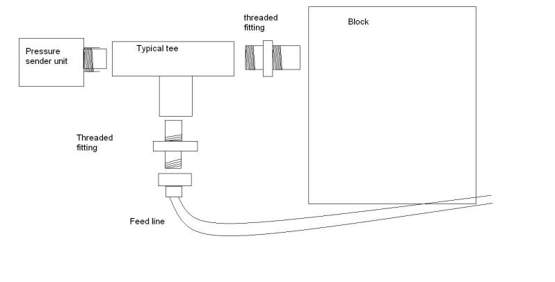
However, no matter what angle I'm coming from, I'm finding it impossible to get the oil feed line on. Front, back, down, up, whatever. Even if I got it on, there's no way in hell I could stick a wrench up there to get it off.
How should I go about this?
However, no matter what angle I'm coming from, I'm finding it impossible to get the oil feed line on. Front, back, down, up, whatever. Even if I got it on, there's no way in hell I could stick a wrench up there to get it off.
How should I go about this?

Reply
 0
0

0
05-08-2010, 08:35 PM
#2
Former Vendor

iTrader: (31)

Join Date: Nov 2006
Location: Sunnyvale, CA
Posts: 15,442
Total Cats: 2,099
1. You're just going to break that "typical" tee anyway, the vibrations from sticking the oil pressure gauge sender on the side of it will break it off the side of the motor
2. Get a BSP to -3AN adapter, bring an AN line up off the side of the block, and then put your pressure sender and oil feed line on a tee that's attached to the firewall. A little more expensive initially, but about a bajillion times easier to install, maintain, and way more reliable.
2. Get a BSP to -3AN adapter, bring an AN line up off the side of the block, and then put your pressure sender and oil feed line on a tee that's attached to the firewall. A little more expensive initially, but about a bajillion times easier to install, maintain, and way more reliable.
Reply
0
0
 05-08-2010, 10:53 PM
#4
Elite Member
Join Date: Mar 2007
Location: Santa Clara, CA
Posts: 5,165
Total Cats: 855
Mine has been mounted just like the diagram (standard FM2 parts) for 8 years and 50K miles now, no vibration damage.
As for installation -- when I put it on the first time, I had the intake manifold off, the second time I had the engine out of the car, so I can't help much.
--Ian
As for installation -- when I put it on the first time, I had the intake manifold off, the second time I had the engine out of the car, so I can't help much.
--Ian
Reply
0
0
05-08-2010, 11:11 PM
#5

I have a steel fitting to the block but I did basically what's in your diagram except I positioned the t to keep the weight closer to the block (|->Block vs your T>Block) for less leverage. I had some issues mounting it (removed the intake mani brace) but it wasn't that hard from under the car.
Do this part right (...every part really), you don't want to do it twice. I would've done it the way Savington describes but I had all the parts already to do it the way I did.
Do this part right (...every part really), you don't want to do it twice. I would've done it the way Savington describes but I had all the parts already to do it the way I did.
Reply
0
0
05-09-2010, 12:46 AM
#6

Mine is the same as your diagram only the T has male threads on the side going into the block so no need for that threaded fitting.
Been working fine for ~2 years now and all the parts came off my old escort gt that was turboed for about a year or so.
Stubby wrenches definitely help for getting up in there.
Been working fine for ~2 years now and all the parts came off my old escort gt that was turboed for about a year or so.
Stubby wrenches definitely help for getting up in there.
Reply
0
0

 05-10-2010, 12:50 AM
#10
Junior Member
Join Date: Aug 2008
Location: Boston
Posts: 223
Total Cats: 0
2. Get a BSP to -3AN adapter, bring an AN line up off the side of the block, and then put your pressure sender and oil feed line on a tee that's attached to the firewall. A little more expensive initially, but about a bajillion times easier to install, maintain, and way more reliable.
http://www.discounthydraulichose.com...m?1=1&CartID=0
9002-04-02 is a BSP to -4 AN flare (more or less).
Steel industrial fittings are way way cheaper than aluminum race car parts.
Reply
0
0
05-10-2010, 12:59 AM
#11

. . .2. Get a BSP to -3AN adapter, bring an AN line up off the side of the block, and then put your pressure sender and oil feed line on a tee that's attached to the firewall. A little more expensive initially, but about a bajillion times easier to install, maintain, and way more reliable.
Reply
0
0
05-10-2010, 01:01 AM
#12
It can be pretty cheap too, e.g.:
http://www.discounthydraulichose.com...m?1=1&CartID=0
9002-04-02 is a BSP to -4 AN flare (more or less).
Steel industrial fittings are way way cheaper than aluminum race car parts.
http://www.discounthydraulichose.com...m?1=1&CartID=0
9002-04-02 is a BSP to -4 AN flare (more or less).
Steel industrial fittings are way way cheaper than aluminum race car parts.
Reply
0
0
05-10-2010, 08:50 AM
#13
Junior Member
Join Date: Aug 2008
Location: Boston
Posts: 223
Total Cats: 0
Well, the oil pressure sensor has a sealing washer. It seems odd that they'd use tapered threads and a sealing washer.
I can tell you that the fitting I mentioned threads into my 1996 block perfectly. I haven't actually fired it up yet so I can't tell you any more than that.
I can tell you that the fitting I mentioned threads into my 1996 block perfectly. I haven't actually fired it up yet so I can't tell you any more than that.
Reply
0
0
05-10-2010, 11:09 AM
#14
Elite Member
Join Date: Mar 2007
Location: Santa Clara, CA
Posts: 5,165
Total Cats: 855
--Ian
Reply
0
0
05-10-2010, 01:34 PM
#15

I can attest to brass fittings breaking off in the block. Happened on my SR20DET. Luckily I saw the trail of oil before I completely lost oil pressure. I even had an oil pressure gauge, but I didn't see it go to 0. Use Steel as suggested or move the T fitting somewhere else!
Reply
0
0
05-10-2010, 03:42 PM
#16

1. You're just going to break that "typical" tee anyway, the vibrations from sticking the oil pressure gauge sender on the side of it will break it off the side of the motor
2. Get a BSP to -3AN adapter, bring an AN line up off the side of the block, and then put your pressure sender and oil feed line on a tee that's attached to the firewall. A little more expensive initially, but about a bajillion times easier to install, maintain, and way more reliable.
2. Get a BSP to -3AN adapter, bring an AN line up off the side of the block, and then put your pressure sender and oil feed line on a tee that's attached to the firewall. A little more expensive initially, but about a bajillion times easier to install, maintain, and way more reliable.
Listen to Sav. I forgot to tighten my oil feed line at the sender. It's tee'd like your picture. Sender perpendicular to motor and oil feed running parallel toward rear. It was a MF to get a wrench up there past the starter and oil sending unit. It would have been so easy to remote mount that sending unit. Probably only cost an extra 10 bucks.
Reply
0
0
05-10-2010, 04:38 PM
#17
Boost Pope

iTrader: (8)
Join Date: Sep 2005
Location: Chicago. (The less-murder part.)
Posts: 33,020
Total Cats: 6,588
For anyone who has a serious aversion to buying anything that's spec'd as JIC, you can get BSP to AN and BSP to NPT adapters here as well: http://www.pegasusautoracing.com/pro...p?Product=3230
Note that some of those fittings are steel, and others aluminum. Shop wisely.
Reply
0
0
05-10-2010, 06:05 PM
#18
Junior Member
Join Date: Aug 2008
Location: Boston
Posts: 223
Total Cats: 0
Anyone serious enough to care about JIC vs AN should machine the block to take an ORB fitting.
Anyway, I just measured my stuff. The oil pressure sensor is indeed tapered. The BSPP fitting with the O-ring seal fits perfectly and threads in easily by hand. I don't have an inside micrometer so I can't measure this, but it could be that the block is not tapered but the sensor is.
Pics


Anyway, I just measured my stuff. The oil pressure sensor is indeed tapered. The BSPP fitting with the O-ring seal fits perfectly and threads in easily by hand. I don't have an inside micrometer so I can't measure this, but it could be that the block is not tapered but the sensor is.
Pics
Reply
0
0
05-10-2010, 06:47 PM
#19
Boost Pope
iTrader: (8)
Join Date: Sep 2005
Location: Chicago. (The less-murder part.)
Posts: 33,020
Total Cats: 6,588
For the record, a standard JIC connector has the same 37� mating surface as an AN connector. There is a subtle difference in the specifications for the thread shape, however from a practical standpoint, the two are identical.
That O-ring fitting is pretty neat. Hadn't seen those before.
Reply
0
0
05-14-2010, 09:58 PM
#20
Want fries with that?
Thread Starter
iTrader: (3)
Join Date: Oct 2009
Location: Twin Cities, Minnesota
Posts: 2,011
Total Cats: 2
Ok, I have re-done it:
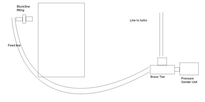
So just a fitting and a line are on the block now, and it runs all the way up to a tee mounted in the old oil recicrulation clip things. From the tee the line to the turbo and the pressure sender unit are connected.
Does this look good? Easier access for sure.
So just a fitting and a line are on the block now, and it runs all the way up to a tee mounted in the old oil recicrulation clip things. From the tee the line to the turbo and the pressure sender unit are connected.
Does this look good? Easier access for sure.
Reply
0
0

Thread
Thread Starter
Forum
Replies
Last Post
Frank_and_Beans
Supercharger Discussion
13
09-12-2016 08:17 PM


