Help with LC-1 / Megasquirt wiring, lots of pictures, tell me what I did wrong.

 03-19-2016, 05:57 PM
#22
Boost Czar


iTrader: (62)
Join Date: May 2005
Location: Chantilly, VA
Posts: 79,493
Total Cats: 4,080
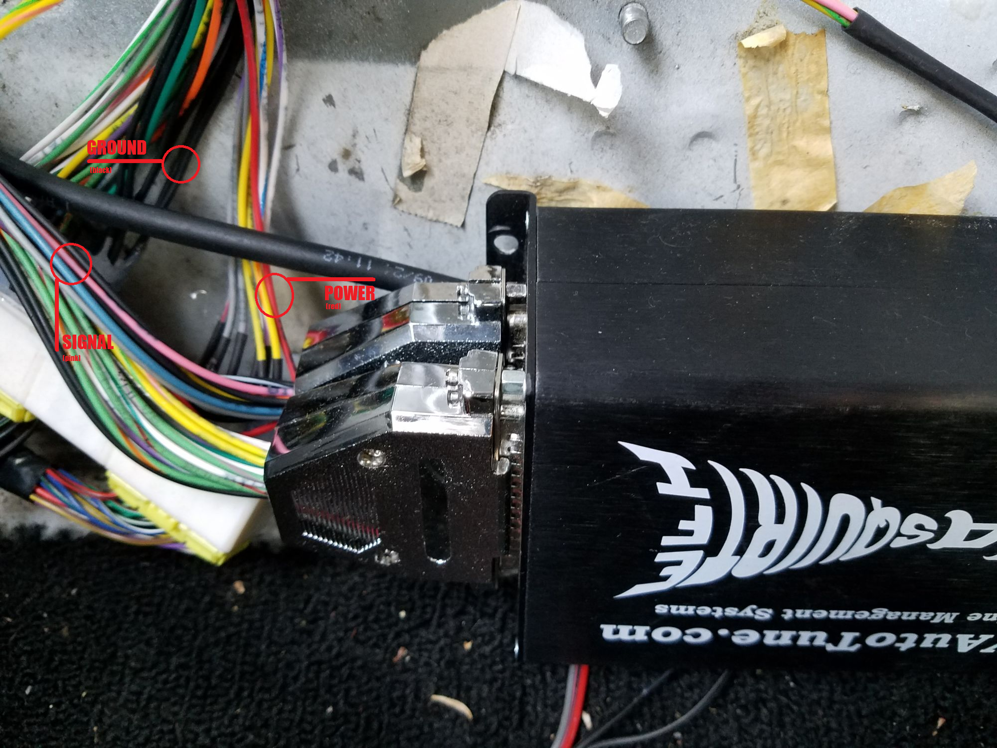
I'd source power off the solid red wire on this harness. and I'd also source my ground there as well, using one of the pair of solid black wires that doubles on the very inside-end of the harness.

Reply
 1
1

1
03-19-2016, 11:56 PM
#23
Junior Member
Thread Starter

Join Date: Feb 2015
Location: South Lake Tahoe
Posts: 105
Total Cats: 1
You can see in the picture where I took a reading of the voltage coming out of the power wire, that would go into the gauge. There is power present, however I don't think it's enough. If it is, then the gauge is broken.
Would I do something like this?
Reply
0
0
03-20-2016, 07:03 PM
#24
Junior Member

Join Date: Oct 2015
Location: Stockholm, Sweden
Posts: 89
Total Cats: 11
That video shows just twisting the wires together, and he mentions just covering it in tape. I would not ever do that in a car for anything important, if you tug on it it can come apart pretty easily no matter how neatly it's twisted up.
I usually go with butt crimp connectors when doing stuff like this. With a connector of the right size you can fit two cables in one side and one in the other.
Soldering works, but it doesn't react to well to repeated temperature changes or stress (tugging cable or maybe severe vibration). It's also usually pretty tricky to do in a car wiring, as it's often cramped for space and easy to accidentally melt insulation on other wires or burn carpets or whatever.
Reply
1
1
03-20-2016, 07:15 PM
#25
Boost Czar
iTrader: (62)
Join Date: May 2005
Location: Chantilly, VA
Posts: 79,493
Total Cats: 4,080
that's actually a very good method if you dont want to cut and re-secure. But I'd also hit it with solder. But the problem is how it makes the orginal wire all funky for routing:
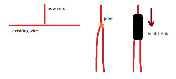
I do like the idea of basically cutting the wire, then using a butt-end crimp to put it back together with two wires going in on one side. Probably the easiest/quickest way to do it as well. I like the crimps with integrated heatshrink, but you need to make sure you get a really good crimp on these, you wouldn't want your power wire to fall out.
But just fwiw, that harness I'm suggesting he tap into is completely soldered together. it's inside the cabin and won't be subject to temp changes or stress.
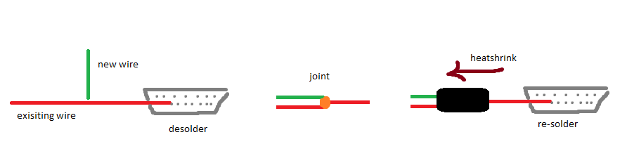
So with that said, those wires are also really easy to desolder from the db37 cup so you can do the crimp like above, and then run the heatshrink down the existing wire. That way the orginal wire doesnt have to get all funky for a more clean install like such:
This thread and others like it have made me rework my wbo2 wiring for my ms3x harnesses to make it much much much easier.
I do like the idea of basically cutting the wire, then using a butt-end crimp to put it back together with two wires going in on one side. Probably the easiest/quickest way to do it as well. I like the crimps with integrated heatshrink, but you need to make sure you get a really good crimp on these, you wouldn't want your power wire to fall out.
But just fwiw, that harness I'm suggesting he tap into is completely soldered together. it's inside the cabin and won't be subject to temp changes or stress.
So with that said, those wires are also really easy to desolder from the db37 cup so you can do the crimp like above, and then run the heatshrink down the existing wire. That way the orginal wire doesnt have to get all funky for a more clean install like such:
This thread and others like it have made me rework my wbo2 wiring for my ms3x harnesses to make it much much much easier.
Last edited by Braineack; 03-20-2016 at 07:29 PM.
Reply
2
2
03-21-2016, 06:23 AM
#27
Junior Member
Join Date: Oct 2015
Location: Stockholm, Sweden
Posts: 89
Total Cats: 11
If you can unsolder/remove one end of the cable from the connector or just cut it at the splice in order to fit shrink tubing over it, that's what will probably look the neatest (crimp connectors do look a bit ugly in the eyes of some people). If you're soldering it, it won't matter too much to the end result if you cut the cable or just strip the insulation, what is easier depends a bit on how much room and slack you have. Though if you manage to get the insulation off neatly, it's probably easier to twist+solder the strands together if you don't have it cut (so you just have two cables instead of three).
Any of these methods (soldering, crimping, or just twisting wires and covering in tape and zipties) will work well if done properly, and can go bad if not. Go with whatever you feel comfortable with and have tools for, and if you're in any way unsure it's easy enough to practice on some spare bits of cable before going wild on your wiring loom.
Reply
1
1
03-21-2016, 07:11 AM
#29
I am QBC, prince of Eternia and defender of the secrets of Castle MiataTurbo. This is Cringer, my fearless friend.
Fabulous secret powers were revealed to me the day I held aloft my magic banhammer and said, “By the power of MiataTurbo! I have the power!“
Cringer became the mighty Battle Cat, and I became He-Man, the most powerful man in the universe!
Only three others share this secret — our friends, the Sorceress, Man-at-Arms, and Orko. Together we defend Castle MiataTurbo from the evil forces of bad advice.
Reply
1
1
03-21-2016, 09:23 AM
#30
Junior Member
Join Date: Oct 2015
Location: Stockholm, Sweden
Posts: 89
Total Cats: 11
Given the right kind of tape, the right circumstances when applying it and the right long-term luck, it can work, but way too often doesn't for it to be useful.
Reply
0
0
03-21-2016, 09:40 AM
#31
Senior Member

Join Date: Aug 2007
Posts: 574
Total Cats: 44
Also, as far as solder goes, the OP should only do it if they know how to properly solder. I have seen far too many bad solder jobs on wiring connections to ever recommend it to someone who doesnt know what they are doing.
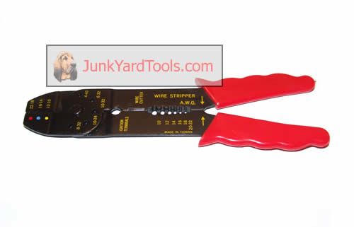
If you do butt connectors, they need to be GOOD ones crimped with a proper tool. NOT like the one below.
Reply
0
0
03-21-2016, 10:16 AM
#32
Junior Member
Join Date: Oct 2015
Location: Stockholm, Sweden
Posts: 89
Total Cats: 11
I have one that looks like this, and it does a good job:
Provided you use the right size die for the connector (hint: match the colors), and the connector size matches the wire, it has always given me solid connections. Also very useful (almost necessary) if you're doing relays, fuses or switches with those flat terminals whose name in English I do not know.
Don't go too cheap on the crimp connectors though. Some have crappy brittle plastic that will break at the crimp, there are also those where the metal is too thin or fragile (low-grade chinesium) and just won't hold the cable properly. I've only gotten bad connectors in some cheap assortment gas-station kits with very many different kinds (which you would probably expect to see bundled with a really shitty crimp tool).
Reply
0
0
03-21-2016, 10:32 AM
#33
Senior Member
Join Date: Aug 2007
Posts: 574
Total Cats: 44
those will do it. I personally prefer un insulated crimps in conjuction with heat shrink. those tend to work the best and you arent dealing with shitty plastic on the connectors. If you go look at oem connections, they use bare crimps and heat shrink.
For my multiple connections, i generally use splice packs that i have collected over the years from trucks i have worked on. Thats usually how i feed power and ground up to the gauges so that i am not running multiple wires all over the place.
For my multiple connections, i generally use splice packs that i have collected over the years from trucks i have worked on. Thats usually how i feed power and ground up to the gauges so that i am not running multiple wires all over the place.
Reply
1
1
03-21-2016, 03:28 PM
#34
Junior Member
Thread Starter
Join Date: Feb 2015
Location: South Lake Tahoe
Posts: 105
Total Cats: 1
Theoretically, could I just pull this wiring mess out, and test this thing directly with my car's battery?
If not, then I'm going to splice into the ECU power and ground as Braineack kindly suggested.
My main issue, is that I don't want to harm wiring to find out that this wideband is trash, and purchase a new one where installation might be simpler, to be left with a new wideband, and an ugly wiring harness.
lol I hope that sentence made sense.
Reply
0
0
03-21-2016, 03:51 PM
#35
Senior Member
Join Date: Aug 2007
Posts: 574
Total Cats: 44
any way you go you will be wiring in power and ground to the wideband.
However, you could just go right to the battery for the power and ground to see if it will power up. i would use a little inline fuse just in case.
However, you could just go right to the battery for the power and ground to see if it will power up. i would use a little inline fuse just in case.
Reply
1
1
03-21-2016, 05:29 PM
#36
Junior Member
Thread Starter
Join Date: Feb 2015
Location: South Lake Tahoe
Posts: 105
Total Cats: 1
I know I'll be wiring in whatever wideband I choose, and doing it properly.
However, this entire adventure was meant to find out if this LC-1 worked lol. All of the info I have gotten has been a tremendous help, and will be used for my permanent install.
It seems that If I can just press all the wires on their respective battery terminals, and check to see if this works, that that would be a lot faster, and safer.
I'd really rather only have to splice into my wiring one time, for a permanent install.
Reply
0
0
03-21-2016, 08:58 PM
#39
Junior Member
Thread Starter
Join Date: Feb 2015
Location: South Lake Tahoe
Posts: 105
Total Cats: 1
I think it's best I drop the cash on a new wideband and save myself the hassle.
I'll be using this thread for reference. Anyone have any suggestions between the MTX-L and AEM UEGO?
Reply
0
0
03-21-2016, 10:04 PM
#40
Senior Member
Join Date: Aug 2007
Posts: 574
Total Cats: 44
i have used the MTX-L without problems. I just installed one in my personal car.
Look it up on jet.com , i got mine from there. It was listed for 150 and you get 15% your first purchase. it was about 126 shipped.
Look it up on jet.com , i got mine from there. It was listed for 150 and you get 15% your first purchase. it was about 126 shipped.
Reply
1
1


