Intake manifold build


 06-27-2012, 01:11 AM
#190
Senior Member
Thread Starter
iTrader: (5)

Join Date: Jan 2008
Location: Central, TX / Bay area, CA
Posts: 1,260
Total Cats: 5
[IMG]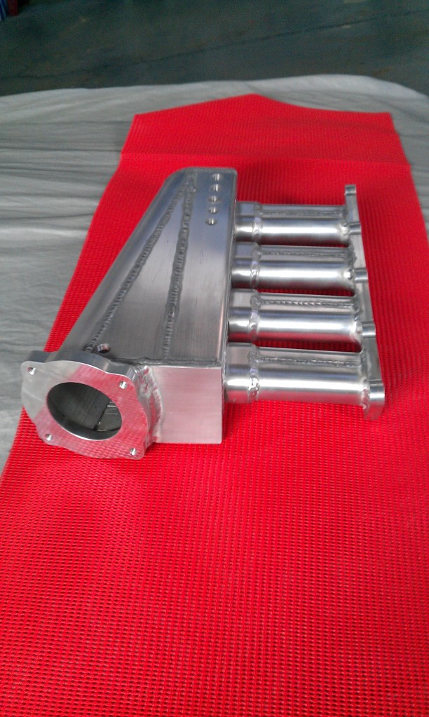 [/IMG]
[IMG]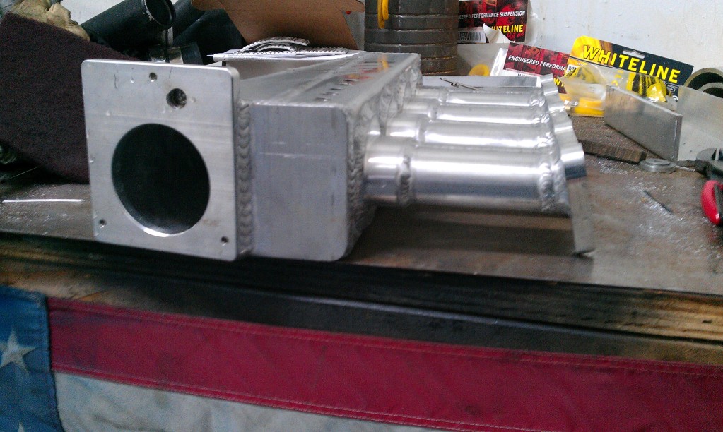 [/IMG]
[IMG]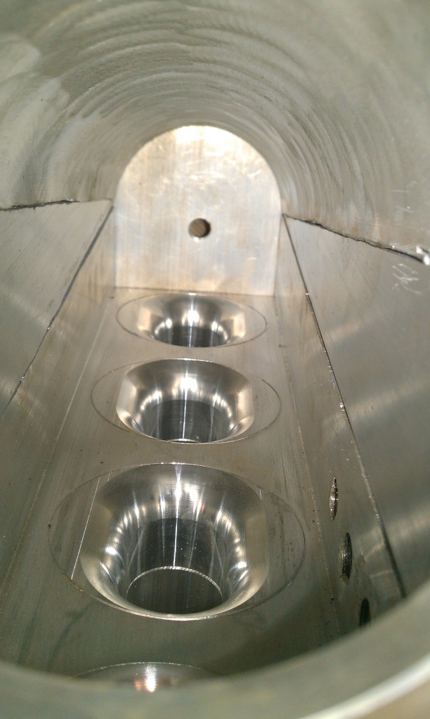 [/IMG]
Here is some newer pics, and one of a flush mount velocity stack done recently.
Also shown in the pics is the new tapering runners.
[/IMG][IMG]
[/IMG][IMG]
[/IMG]Here is some newer pics, and one of a flush mount velocity stack done recently.
Also shown in the pics is the new tapering runners.

Reply
 1
1

1


 06-27-2012, 12:05 PM
#197
sounded like he was explaining what the velocity stacks are for to me..
Just think of a tapered runner as a very subtle velocity stack. By starting out with a larger diameter than the intake port of the head the effective unrestricted flow area can be equivalent to that of the head intake port diameter.
Notice the smaller unrestricted flow CSA (cross sectional area) in the top image. this same effect happens at the base of the velocity stack although it is not shown in the picture. The tapered runner helps combat the effects of this turbulence.
Reply
0
0
06-27-2012, 12:53 PM
#199
Boost Czar


iTrader: (62)
Join Date: May 2005
Location: Chantilly, VA
Posts: 79,493
Total Cats: 4,080
it's just good practice. you want good flow: use a stack. you want to stuff a ---- ton of air as fast as possible into a container: taper the runner to increase velocity.
Reply
0
0


