Intake Manifold Design Question
 05-11-2009, 11:14 AM
#41
Boost Pope


iTrader: (8)
Join Date: Sep 2005
Location: Chicago. (The less-murder part.)
Posts: 33,015
Total Cats: 6,587
Originally Posted by Joe Perez

The thinking here is that, assuming I accept on faith that a plenum chamber and short(ish) runners are most optimum from an efficiency standpoint, how to eliminate the effect illustrated by Braineak above, where distribution of air across the various ports is uneven? Answer: Locate the throttle body such that it is equally proximate to all ports, such that the geometry between the throttle body and the ports is roughly similar for all of them, and eliminate the sort of ram-air effect that I perceive taking place when air enters one end of the plenum and travels along its length to a wall on the other end.
One way to do this would be to use a single throttle body mounted in the middle of the plenum, and that's probably a lot better design than putting it at one end of the plenum. Putting two, smaller throttle bodies on the plenum, such that each one is centered between a pair of ports, may be better still.
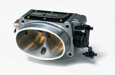
One could use two small throttle bodies, or one could use a two-port throttle body such as this one:
In such a design, the throttle body might want to be spaced off of the plenum just a bit, with individual runners from each port going out to the "ideal" locations on the plenum. It might be located beneath the plenum from a space-constraint standpoint.
Just thinking out loud here in terms of what constitutes a "most optimum" design.
Originally Posted by SamNavy
Are all 1.6 heads the same?

Reply
 0
0

0
 05-11-2009, 07:51 PM
#43
Junior Member

Join Date: Mar 2009
Location: Venice, FL
Posts: 173
Total Cats: 9
I feel it is necessary to mention that the second biggest upgrade for the MkIII Supra is switching away from the side facing throttle body.
I'm 95% sure that the reason Porsche and Scoobaru do it is due to fitment. Toyota loved the idea and put it on everything sporty in the 80s, N/A or turbo. There is no better way to lengthen your intake unnecessarily than to move the TB to the side of the manifold.
In my case, the added piping to have the throttle body on the side not only probably looses boost through pressure drop, but goes right over the turbo and wastegate after coming from the intercooler.
I think the ideal manifold is a tapered design:
 .
.
IMO, the runners are too short for a street car, but it does get up to boost that much quicker.
I'm 95% sure that the reason Porsche and Scoobaru do it is due to fitment. Toyota loved the idea and put it on everything sporty in the 80s, N/A or turbo. There is no better way to lengthen your intake unnecessarily than to move the TB to the side of the manifold.
In my case, the added piping to have the throttle body on the side not only probably looses boost through pressure drop, but goes right over the turbo and wastegate after coming from the intercooler.
I think the ideal manifold is a tapered design:
.IMO, the runners are too short for a street car, but it does get up to boost that much quicker.
Reply
0
0


 05-12-2009, 10:26 AM
#46
Boost Pope
iTrader: (8)
Join Date: Sep 2005
Location: Chicago. (The less-murder part.)
Posts: 33,015
Total Cats: 6,587
I'm 95% sure that the reason Porsche and Scoobaru do it is due to fitment. Toyota loved the idea and put it on everything sporty in the 80s, N/A or turbo. There is no better way to lengthen your intake unnecessarily than to move the TB to the side of the manifold.
Reply
0
0
05-12-2009, 11:04 AM
#47
Junior Member
Join Date: Mar 2009
Location: Venice, FL
Posts: 173
Total Cats: 9
No question that the VW/Scooby design is a matter of mechanical necessity. But with regard to the design I posited above, I don't see how it increases the length or volume of the system above the stock design. All I'm doing really is moving the throttle from the front to the side in order to reduce the uneven distribution of air across the ports.

Still one throttle body, but splits into two like your design.
On an inline engine, a side mounted throttle body seems to be mostly inconvenient as far as intake routing. The extra turns that the air would have to do in addition to the inconvenient mounting and routing of piping--again, in my opinion--do not justify the relocation of the throttle body.
The intake/intercooler piping would have to be routed over the engine, where there is little clearance and plenty more heat. It might not heat the piping up much if you do it right, but enough that it should matter to someone who's playing scientist with the TB location. Its easier to do on an I4, but still annoying.
I rather like the Quad4's IM though, that looks cool.
Reply
0
0
05-12-2009, 01:56 PM
#48
Found this to be a decent read... Figured I would pass it along.
Intake Manifolds: From Mild to Wild: Engine Builder
Intake Manifolds: From Mild to Wild: Engine Builder
Reply
0
0
05-12-2009, 03:53 PM
#49
Elite Member
iTrader: (9)
Join Date: Jun 2006
Location: Chesterfield, NJ
Posts: 6,891
Total Cats: 398
Then I started thinking about how some guys take their hot-side pipe and run it through the fender... and why couldn't you do that on the intake side. I did a Google image search and found a few examples, but made a paint too. You could even angle the thing down and come up behind the alternator... there are a few options.


Reply
0
0
05-12-2009, 04:29 PM
#50
Found this link as well while searching over at the Grassroots Motorsports forum... Might be a great place to buy some starting materials for a DIY build. 
Intake Manifold and Fuel Rail Parts - Ross Machine Racing
Intake Manifold and Fuel Rail Parts - Ross Machine Racing
Reply
0
0
05-13-2009, 02:34 PM
#51
I myself am SERIOUSLY considering a build from Ross' D Shaped Plenum... Based on some calculations of volume; the area of the internal portion of the plenum at 1 cm of length is 94.475 cm�. Seeing as 1 cm� = 1 mL, to reach a internal plenum volume of 2000 mL or 2 L (or whatever you plan to use), one would need this plenum with a length of 21.18 cm (for the 2 L example). Sounds like a doable project to me. If you need additional volume just make it a little longer on either end and you're good to go.
Discuss...
Discuss...
Reply
0
0
05-13-2009, 05:10 PM
#52
Boost Czar

iTrader: (62)
Join Date: May 2005
Location: Chantilly, VA
Posts: 79,483
Total Cats: 4,076
I bought my TB flange from them. but otherwise I found it expensive.
I have a 4" plenum that's roughly 13.5" long...so somewhere in the 170 Cu.in. range.
1.74X the volume of the motor...probably a little more due to the end caps.
I have a 4" plenum that's roughly 13.5" long...so somewhere in the 170 Cu.in. range.
1.74X the volume of the motor...probably a little more due to the end caps.
Reply
0
0
05-13-2009, 05:11 PM
#53
Former Vendor
iTrader: (8)

Join Date: Mar 2005
Location: Broken Arrow,Ok
Posts: 1,185
Total Cats: 57
thegr81, I have thought about this myself, but it still doesn't account for the entry angle that has been discussed. I'm getting the itch to make one similar to the one of the 7M supra above that has offset angle entry. Continue discussion.
-Michael
-Michael
Reply
0
0
05-13-2009, 05:33 PM
#54
Elite Member
iTrader: (15)

Join Date: Dec 2007
Location: San Antonio, Texas
Posts: 4,847
Total Cats: 27
IIRC wasn't the outside of the manifold ceramic coated somehow?
Reply
0
0
 05-13-2009, 07:26 PM
#57
 ), correct? That would potentially make clearance a bit difficult on the hood. I totaled up the parts I would need with some excess and it came out to be right around $400 or so. Welding and cutting will be free. I might go for it... Will take awhile before it's functional as the engine and car are in pieces right now. The 7M one above is similar to what JUN does for their IM's which seem to flow VERY well up top and with big engines. Might be worth a shot...
Reply
0
0
05-13-2009, 08:37 PM
#58
I myself am SERIOUSLY considering a build from Ross' D Shaped Plenum... Based on some calculations of volume; the area of the internal portion of the plenum at 1 cm of length is 94.475 cm�. Seeing as 1 cm� = 1 mL, to reach a internal plenum volume of 2000 mL or 2 L (or whatever you plan to use), one would need this plenum with a length of 21.18 cm (for the 2 L example). Sounds like a doable project to me. If you need additional volume just make it a little longer on either end and you're good to go.
Discuss...
Discuss...
i decided against this, i thought its was to thick, and if i recall, the i.d volume was to small, the plenum would have to be really long to get the correct volume. no need for .250 thick, i went with .125 and started with a 5" round and milled it down to make a d shape plenum
Reply
0
0
 The i.d. is 4.5" and based on the internal area this plenum should be PLENTY to flow... As 22 cm is only 8.66 inches... I think it would work alright with the right equipment.


