ITT: fmic size and piping diameters for optimum efficiency
 11-18-2012, 04:22 PM
#21

every thread I just read the inputs are all 50/50 ARRRRRGHHHH
Jason and Brain so far are the only people that actually stated NUMBERS of how much something changed vs just ranting on and on about how they think its better and bla bla bla bullshit that helps no one. I guess that's why this site is one of the best on the webbernetz, lol
So far this is what I gather:
deltafin - better response due to less restrictions and larger tubes, and passes more air through itself and onto the radiator. So pluses and minuses.
bar/plate - holds up to higher pressures better, is sturdier, and possibly has more turbulators inside? again, pluses and minuses.
Also there's the argument of "what are the top companies using?"
Well ARC, one of the top dogs out there uses tube/fin and deltafin.
But then
Precision, another of the top dogs, use bar/plate.
Lastly, OEM's pretty much all use tube/fin. I wonder why? Simply because its more efficient at lower speeds/pressures, or what reason?
Since my miata will be a daily, I'm starting to kinda lean towards the deltafin??? Iono
I mean it worked great on my previous miata:
But then I never tried a bar/plate so maybe that woulda worked just as well?

Reply
 0
0

0
11-18-2012, 09:51 PM
#22

The type of the core is not nearly as important as the actual efficiency of the core. If you can get a company to give you the results from their testing then you can compare them. If you cant get them to give you the results then they're scared you wont like the results, or they're *****.
On the tube sizing. Theoretically you just want to size it so that the air flow doesnt hit super sonic. HOWEVER drag is a function of the square of velocity and head loss is directly related to velocity, so the slower moving air is going to loose less energy than faster moving air. BUT going larger in pipe diameter also increases your surface area for skin friction and creates a larger volume of air on the surface of the tubing moving at near zero velocity. Basically, fluids is a crap shoot and you either need to test **** empirically or use a computer. Or do the smarter thing and find someone else who has tested it empirically.
Something like this but more precise. numbers in the table are in cfm. Based on this 2 inch pipe at 20 psi can support ~400 hp with a 1psi pressure drop. So based on this chart, which isnt the most accurate thing but has a bunch of safety factor built in you could come close to or hit your 250 hp goal if you were using 20 psi with only 1.5" piping.
Reply
0
0
11-18-2012, 10:25 PM
#24

Tube and fin typically is cheaper to mass produce and IIRC more efficient, thus oem.
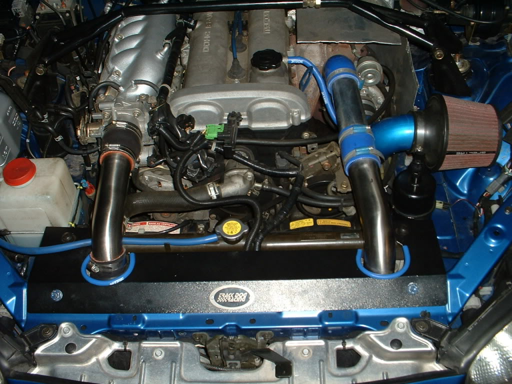
On a previous car I experimented with this and ended up using a mx6 intercooler (top / bottom tanks with rear facing barbs made for SHORT ic piping, something in Corky's book about that I believe) with 2" piping and a 2554 sized ihi at 14psi. It did heat a bit at the top end (tiny turbo) but had awesome response and low end. IIRC it was producing 14psi by 2500rpm and tapered to 13 or 12.5psi at red line.
FWIW I have a BEGI #2 and standard BEGI piping and AIT typically goes up 2-3C under 17psi (stock 97 engine) from a 2560, street driving.
Reply
0
0
11-18-2012, 10:29 PM
#25
The type of the core is not nearly as important as the actual efficiency of the core. If you can get a company to give you the results from their testing then you can compare them. If you cant get them to give you the results then they're scared you wont like the results, or they're *****.
That's what makes this discussion tricky.
I intend to test whatever I get and provide actual results.
On the tube sizing. Theoretically you just want to size it so that the air flow doesnt hit super sonic. HOWEVER drag is a function of the square of velocity and head loss is directly related to velocity, so the slower moving air is going to loose less energy than faster moving air. BUT going larger in pipe diameter also increases your surface area for skin friction and creates a larger volume of air on the surface of the tubing moving at near zero velocity. Basically, fluids is a crap shoot and you either need to test **** empirically or use a computer. Or do the smarter thing and find someone else who has tested it empirically.
Something like this but more precise. numbers in the table are in cfm. Based on this 2 inch pipe at 20 psi can support ~400 hp with a 1psi pressure drop. So based on this chart, which isnt the most accurate thing but has a bunch of safety factor built in you could come close to or hit your 250 hp goal if you were using 20 psi with only 1.5" piping.
Something like this but more precise. numbers in the table are in cfm. Based on this 2 inch pipe at 20 psi can support ~400 hp with a 1psi pressure drop. So based on this chart, which isnt the most accurate thing but has a bunch of safety factor built in you could come close to or hit your 250 hp goal if you were using 20 psi with only 1.5" piping.
This is why I'm waiting for someone to tell me why that may NOT work out. And hopefully present some evidence to prove their claim.
If not, I'll move forward with this plan.
Its a whole helluva lot easier to route 2" on the cold side between the motor and my oversized rad/stock fans, then have a silicone elbow/reducer go into the TB from 2" to 2.5" (actually have one of these already).
Like I said, I will do it if someone tells me that its beneficial (and post up proof or a good argument)

Tube and fin typically is cheaper to mass produce and IIRC more efficient, thus oem.
On a previous car I experimented with this and ended up using a mx6 intercooler (top / bottom tanks with rear facing barbs made for SHORT ic piping, something in Corky's book about that I believe) with 2" piping and a 2554 sized ihi at 14psi. It did heat a bit at the top end (tiny turbo) but had awesome response and low end. IIRC it was producing 14psi by 2500rpm and tapered to 13 or 12.5psi at red line.
FWIW I have a BEGI #2 and standard BEGI piping and AIT typically goes up 2-3C under 17psi (stock 97 engine) from a 2560, street driving.
If so post up AIT's before/after....
Reply
0
0
11-18-2012, 10:40 PM
#26
Why should you do it? Least efficiency losses.
The hot side being the same size as the turbo outlet means you dont have to scram the air into a smaller pipe after it goes up to whatever the turbo outlet size is. Then the cold side wouldnt have to force everything into the smaller pipe just to expand again to the throttle body size. Of course go by the ID of the piping.
I dont know why you've had so many issues with over the rad setup. Mine was simple as all hell and i'm using 2.25s.
Reply
0
0
11-18-2012, 10:46 PM
#27
What does this mean?
The hot side being the same size as the turbo outlet means you dont have to scram the air into a smaller pipe after it goes up to whatever the turbo outlet size is. Then the cold side wouldnt have to force everything into the smaller pipe just to expand again to the throttle body size. Of course go by the ID of the piping.
Yeah except after the air enters the intercooler it still has to be crammed back into a small hole at the end. So whats the difference between a 2" hole and 2.5" hole if for the end result goal the 2" piping is up to the task? (based on the calculations)
I'm not trying to be difficult, I'm just looking for factual evidence.
I dont know why you've had so many issues with over the rad setup. Mine was simple as all hell and i'm using 2.25s.
Whats simple about it?
You need to lower the rad. You also need to tilt it. So either re-locating the lower brackets, the bar, or both. And you need new fans because stockers wont clear. And you need new brackets for the top of the rad. And you need a shroud for the top. That's a ton of stuff, I did a step by step in my 1st build thread. At the time it seemed like a great idea. Then I hated it.
What am I missing here?
The hot side being the same size as the turbo outlet means you dont have to scram the air into a smaller pipe after it goes up to whatever the turbo outlet size is. Then the cold side wouldnt have to force everything into the smaller pipe just to expand again to the throttle body size. Of course go by the ID of the piping.
I'm not trying to be difficult, I'm just looking for factual evidence.
I dont know why you've had so many issues with over the rad setup. Mine was simple as all hell and i'm using 2.25s.
You need to lower the rad. You also need to tilt it. So either re-locating the lower brackets, the bar, or both. And you need new fans because stockers wont clear. And you need new brackets for the top of the rad. And you need a shroud for the top. That's a ton of stuff, I did a step by step in my 1st build thread. At the time it seemed like a great idea. Then I hated it.
What am I missing here?
Reply
0
0
11-18-2012, 10:49 PM
#28
I really dont see why the cold side needs to be larger either except to match the throttle body. You should need less flow cross seciton to move the same mass of air after the intercooler than before it since that air mass will be more dense it will occupy less volume (technically it will always fill the volume since its a fluid and will be at lower pressure but humor me). I would think you would see no losses if you ran two inch the whole way and used a 7.5* draft angle for your taper to the throttle body size. 7.5* draft (aka 15* total) is what we use on the formula car for the expansion after the restrictor we have to run, the University of australia found it to be the best and all our CFD confirmed it. You would have to do your own CFD since this pipe size is larger and you're going to be working with a different density of air, but you will be working with around the same velocities.
Of you could just use 2" and whatever the **** taper you can buy and fits conveniently.
Of you could just use 2" and whatever the **** taper you can buy and fits conveniently.
Reply
0
0
 11-18-2012, 10:53 PM
#30
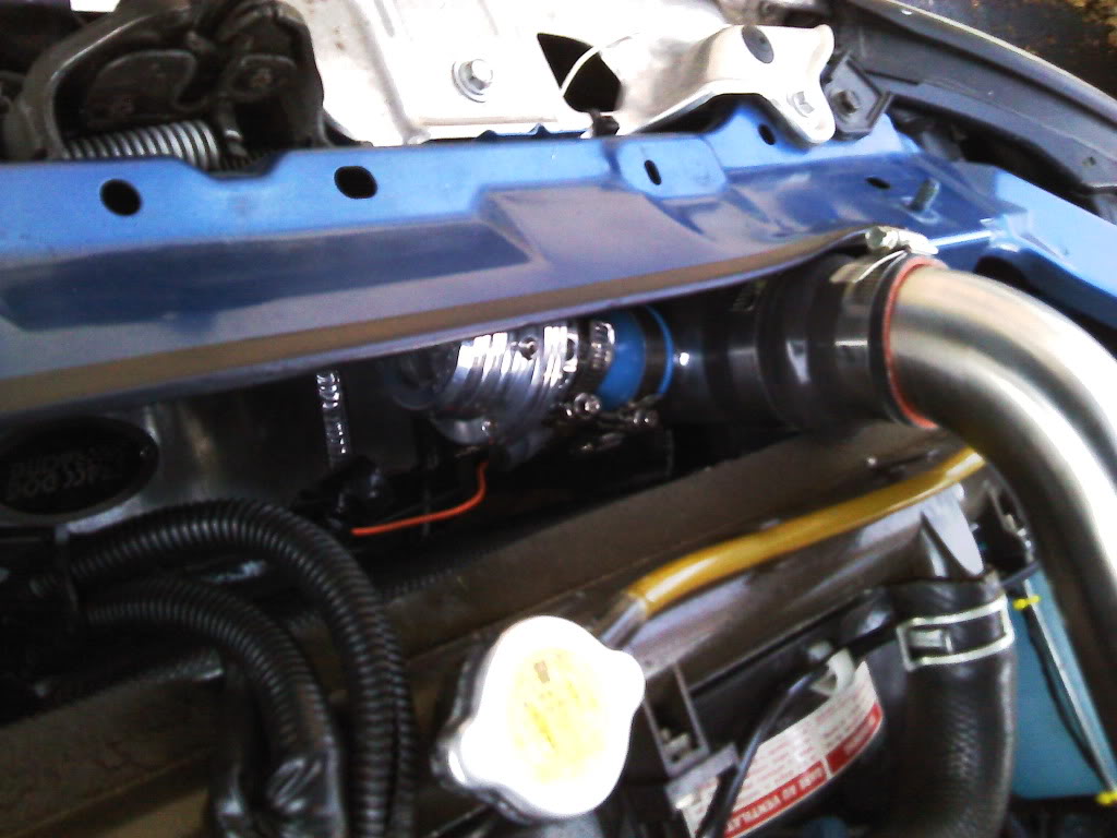
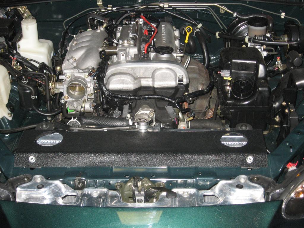
The stock brackets get removed from the stock location, you drill one hole and mount them in the anti sway bar bolts. This will give you enough room for 3" pipes if you cut more of the top support. The stock fans clear, the shrouds clear.
All you need to do is make brackets for the upper radiator support.
Leafy, running bigger than the throttle body colder side will only increase lag a bit but mainly it will make it more difficult since you will have bigger pipe to route. Running smaller will reduce efficiency though per reasons i mentioned above. Take the flow of the engine, take the cc difference of the pipes and see how much extra lag it will cause.. not much.
I finished my ic setup in 4 hours total and that includes going to the hardware to buy stuff since i broke one of the bolts that hold the antisway bar since i decided to be dumb and use my impact wrench.
I also have AC and PS.
Last edited by triple88a; 11-18-2012 at 11:12 PM.
Reply
0
0
11-19-2012, 01:52 AM
#31
Newb

Join Date: Apr 2009
Location: Decatur, Ga
Posts: 29
Total Cats: 5
Ive been researching this as well.
Im cobbling together a system based on the msm hotside pieces for a goal of modest power increase/ minimal tweaking and maximum simplicity. I was unable to secure the oem charge pipes, but having seen how kinky they are, I feel I am just as well to not have em.
If MSM guys top out at 230 at the most, using the turbo to its maximum efficiency, Im wondering if, considering that I am not going to build the engine, there is any reason to go over 1.5 inch charge pipes at any point in the system other than reducers to mate up to the throttle body and intercooler.
This of course presumes that running the smallest pipe to reach your power goals is truly the best choice. For my share, if this car makes 200 at the wheels Ill be happy as a pig in ****.
Theres simply not alot of info on using small pipes like that. Im asking myself if its because of the mental "little dick pipe" factor or if there is a more practical reason not to based on out of boost driveability or flow or some other unaccounted for variable.
Do MSM feel choked out at high rpm?
Reply
0
0
11-19-2012, 07:59 AM
#33

Leafy, running bigger than the throttle body colder side will only increase lag a bit but mainly it will make it more difficult since you will have bigger pipe to route. Running smaller will reduce efficiency though per reasons i mentioned above. Take the flow of the engine, take the cc difference of the pipes and see how much extra lag it will cause.. not much.
It may be that you want that air moving slower (bigger pipe) or faster (smaller pipe) but I doubt it significantly changes the efficiency until you start to get near the limits of the 2" pipe.
Reply
0
0
11-19-2012, 08:26 AM
#34
Why though? I don't have any numbers, but I am going to guess that if 2" is enough for the hotside, why would it not be as efficient on the cold side? Running smaller will only reduce efficiency if you are trying to push more air through it, right? If we are still only pushing 250-300hp worth of air through, I don't see why it wouldn't work.
It may be that you want that air moving slower (bigger pipe) or faster (smaller pipe) but I doubt it significantly changes the efficiency until you start to get near the limits of the 2" pipe.
It may be that you want that air moving slower (bigger pipe) or faster (smaller pipe) but I doubt it significantly changes the efficiency until you start to get near the limits of the 2" pipe.
Reply
0
0
11-19-2012, 08:27 AM
#35
The stock brackets get removed from the stock location, you drill one hole and mount them in the anti sway bar bolts. This will give you enough room for 3" pipes if you cut more of the top support. The stock fans clear, the shrouds clear.
All you need to do is make brackets for the upper radiator support.
[IMG]https://www.miataturbo.net/attachment.php?attachmentid=60218&dateline=1353297 238[IMG]
I finished my ic setup in 4 hours total and that includes going to the hardware to buy stuff since i broke one of the bolts that hold the antisway bar since i decided to be dumb and use my impact wrench.
Like I said, in my 1st build thread, I did it PROPERLY and completely, making sure everything is fastened, shrouded, and correct, and the process I outlined is what it takes to DO IT RIGHT.
And you still end up hacking up the rad support (which is necessary, I had to do it too) to get the pipes to be able to pass through there.
I don't like that. At all.
Leafy, running bigger than the throttle body colder side will only increase lag a bit but mainly it will make it more difficult since you will have bigger pipe to route. Running smaller will reduce efficiency though per reasons i mentioned above. Take the flow of the engine, take the cc difference of the pipes and see how much extra lag it will cause.. not much.
I also have AC and PS.
I also have AC and PS.
I have a feeling you have NO ******* CLUE what it means

I'm trying my hardest to keep this conversation productive, but please, if this is all you have to say just don't post.......This is not the exhaust side. Saying simply "bigger is better" isn't going to cut it.
Ive been researching this as well.
Im cobbling together a system based on the msm hotside pieces for a goal of modest power increase/ minimal tweaking and maximum simplicity. I was unable to secure the oem charge pipes, but having seen how kinky they are, I feel I am just as well to not have em.
If MSM guys top out at 230 at the most, using the turbo to its maximum efficiency, Im wondering if, considering that I am not going to build the engine, there is any reason to go over 1.5 inch charge pipes at any point in the system other than reducers to mate up to the throttle body and intercooler.
This of course presumes that running the smallest pipe to reach your power goals is truly the best choice. For my share, if this car makes 200 at the wheels Ill be happy as a pig in ****.
Theres simply not alot of info on using small pipes like that. Im asking myself if its because of the mental "little dick pipe" factor or if there is a more practical reason not to based on out of boost driveability or flow or some other unaccounted for variable.
Do MSM feel choked out at high rpm?
Im cobbling together a system based on the msm hotside pieces for a goal of modest power increase/ minimal tweaking and maximum simplicity. I was unable to secure the oem charge pipes, but having seen how kinky they are, I feel I am just as well to not have em.
If MSM guys top out at 230 at the most, using the turbo to its maximum efficiency, Im wondering if, considering that I am not going to build the engine, there is any reason to go over 1.5 inch charge pipes at any point in the system other than reducers to mate up to the throttle body and intercooler.
This of course presumes that running the smallest pipe to reach your power goals is truly the best choice. For my share, if this car makes 200 at the wheels Ill be happy as a pig in ****.
Theres simply not alot of info on using small pipes like that. Im asking myself if its because of the mental "little dick pipe" factor or if there is a more practical reason not to based on out of boost driveability or flow or some other unaccounted for variable.
Do MSM feel choked out at high rpm?
Yet people fail to realize that using SMALLER PIPING thats OPTIMAL for the power and flow targets, is the definition of efficiency.
Using LARGER PIPING, that's OVERSIZED for the goals, is in-efficient.
Why though? I don't have any numbers, but I am going to guess that if 2" is enough for the hotside, why would it not be as efficient on the cold side? Running smaller will only reduce efficiency if you are trying to push more air through it, right? If we are still only pushing 250-300hp worth of air through, I don't see why it wouldn't work.
It may be that you want that air moving slower (bigger pipe) or faster (smaller pipe) but I doubt it significantly changes the efficiency until you start to get near the limits of the 2" pipe.
It may be that you want that air moving slower (bigger pipe) or faster (smaller pipe) but I doubt it significantly changes the efficiency until you start to get near the limits of the 2" pipe.
I hope someone smarter than myself regarding these topics can point out the flaw in this logic.
PAGING:
Joe Perez
Brain
y8s
Savington
???????
Anyone else that knows what the word EFFICIENCY means.
Reply
0
0
11-19-2012, 08:30 AM
#36
By my math for the same air mass (aka what directly relates to the power you can make). The hot side intercooler piping should require more flow than the cold side. It will be colder so the molecular drift speed of the air charge will be slower but that is only a noticeable part of the total air velocity in turbulent flow. We should be in transitional flow between the intercooler and the throttle body since the piping isnt really long enough for fully developed flow to develop. Unless you go with a long *** routing then based on my rough math it would develop into turbulent flow.
Reply
0
0
11-19-2012, 08:33 AM
#37
The only way efficiency applies to intercooler piping is pressure drop. The less pressure drop along the piping the more efficient it is. Pressure drop is really easy to calculate, if you know how to find Reynolds number its then a simple bit of math and a look up in some tables for head losses in the bends. And you dont worry about the flow being overly turbulent you worry about it going too fast. You hit super sonic speed and your flow gets fucked.
Reply
0
0
11-19-2012, 01:12 PM
#38
Yeah, except that looks half assed to me and that's not something I'd be proud of or happy with.
Like I said, in my 1st build thread, I did it PROPERLY and completely, making sure everything is fastened, shrouded, and correct, and the process I outlined is what it takes to DO IT RIGHT.
Like I said, in my 1st build thread, I did it PROPERLY and completely, making sure everything is fastened, shrouded, and correct, and the process I outlined is what it takes to DO IT RIGHT.
Theres nothing half assed about that setup. I actually took the top cover off 2 days ago... everything is tight as it gets.
Reply
0
0
11-19-2012, 02:49 PM
#39
Newb
Join Date: Apr 2009
Location: Decatur, Ga
Posts: 29
Total Cats: 5
My over the radiator setup is going to be similar to yours. I didnt have the nice TDR pieces to work with, so I made some ABS ones. I actually had to mount the radiator in the old AC condensor hole locations to tilt the rad forward at the bottom. the intercooler Im using is unusually large for this sort of setup. Ill probably run 2 inch piping, cause why not? it will be fine, and not as close to critical mach as 1.5 would be for the power Im aiming for.
exhaust is going to be 2.5............most limiting factor in my setup is the turbo, but hell. if its good up to power levels that exceeding would necessitate building the engine, Im going to use it. It was cheap and is in good shape. fuggit.
exhaust is going to be 2.5............most limiting factor in my setup is the turbo, but hell. if its good up to power levels that exceeding would necessitate building the engine, Im going to use it. It was cheap and is in good shape. fuggit.
Reply
0
0


