ITT: We discuss electronic wastegate ideas
 04-02-2015, 01:40 PM
#1
SADFab Destructive Testing Engineer


Thread Starter
iTrader: (5)
Join Date: Apr 2014
Location: Beaverton, USA
Posts: 18,642
Total Cats: 1,866
Pretty simple idea. PWM controlled linear actuator connected to the wastegate flapper. I can figure out the electronics for it but some discussion on the forces required, how strong/quick of an actuator is needed would be fun. I have some free stuff at work and want to play with some ideas.
Discuss.
Discuss.

Reply
 0
0

0
04-02-2015, 02:43 PM
#2
Boost Pope

iTrader: (8)
Join Date: Sep 2005
Location: Chicago. (The less-murder part.)
Posts: 33,026
Total Cats: 6,592
Interesting, as I've long pondered a similar concept, using an electrically operated bypass valve in a compount (turbo-supercharger) application, to fully bypass the supercharger once the turbo's boost threshold has been achieved.
Not that I ever plan to build such a thing...
I've heard tell that some WWII aircraft engines had turbochargers with electrically operated wastegates, allowing the pilot to dial in different pressure ratios from the cockpit. A quick search also shows some more recent work in the field.

In theory, computing how much force you need is easy. Measure the pressure inside the turbine housing under full load with WG closed, and multiply that against the exposed surface area of the wastegate valve. You just need to drill a hole in your turbine to mount the probe and you'll be good to go.
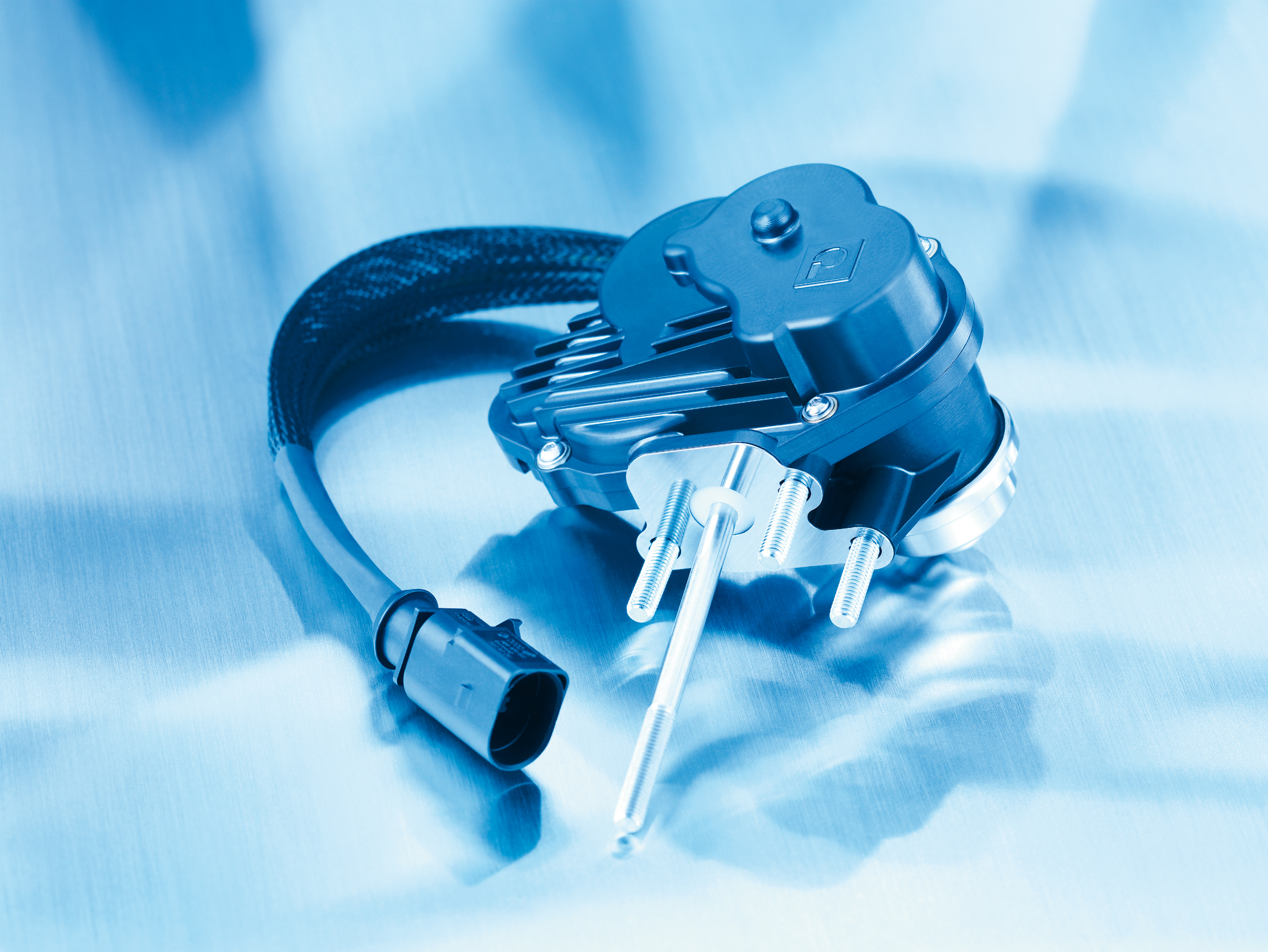
This press release talks about an electrically operated wastegate for OEM applications: KSPG AG: Electric wastegate actuator ready for volume production
Not that I ever plan to build such a thing...
I've heard tell that some WWII aircraft engines had turbochargers with electrically operated wastegates, allowing the pilot to dial in different pressure ratios from the cockpit. A quick search also shows some more recent work in the field.
In theory, computing how much force you need is easy. Measure the pressure inside the turbine housing under full load with WG closed, and multiply that against the exposed surface area of the wastegate valve. You just need to drill a hole in your turbine to mount the probe and you'll be good to go.
This press release talks about an electrically operated wastegate for OEM applications: KSPG AG: Electric wastegate actuator ready for volume production
Reply
0
0
04-02-2015, 02:44 PM
#3
SADFab Destructive Testing Engineer
Thread Starter
iTrader: (5)
Join Date: Apr 2014
Location: Beaverton, USA
Posts: 18,642
Total Cats: 1,866
Wikipedia says electronic control in aircraft was tossed because there was a requirement of separating the electronic systems from the mechanical systems or something.
Reply
0
0
04-02-2015, 02:57 PM
#4
Boost Pope
iTrader: (8)
Join Date: Sep 2005
Location: Chicago. (The less-murder part.)
Posts: 33,026
Total Cats: 6,592
There's long been a superstitious prejudice against electronics on the part of airplane designers and engineers. As late as the 1990s, light, single-engine airplanes were still capable of flying with no functioning electrical system of any kind; the ignitions were magneto-operated and the fuel delivery was a mechanical carburetor with manual mixture control. Once the engine was started, it'd keep running until it ran out of gas even if the alternator and battery were both completely disabled.
That said, I'm a little curious about the ability of your linear actuators to tolerate the heat that will be experienced by a device located an inch or two away from a part of the engine which sometimes glows cherry-red.
Reply
0
0
 04-02-2015, 03:11 PM
#6
Junior Member

Join Date: Dec 2014
Location: Boston, MA
Posts: 196
Total Cats: 14
I spent half an hour discussing this with a buddy. I'm a firm believer that it's possible. My solution to the heat problem was a remote mount with a cable linkage, although I'm not convinced can't design a solenoid to take it.
For what it's worth Bosch makes one, but it looked if you have to ask expensive.
For what it's worth Bosch makes one, but it looked if you have to ask expensive.
Reply
0
0
04-02-2015, 03:20 PM
#7
Boost Pope
iTrader: (8)
Join Date: Sep 2005
Location: Chicago. (The less-murder part.)
Posts: 33,026
Total Cats: 6,592
It's not especially easy to PWM-drive a solenoid against a heavy load. A servo would be far better suited to such a task, which I assume is what aidandj meant when he talked about linear actuators. (Many servos, such as those used on remote-controlled cars and airplanes, use a PWM control signal and adjust their position to the duty cycle of the PWM signal. This is a very different thing from just directly PWMing a solenoid.)
Serious question: what would the advantage be of such an arrangement (cable linkage, servo / solenoid, etc) as compared to an air-powered diaphragm controlled by a solenoid-operated air valve?
Reply
0
0
 04-02-2015, 03:33 PM
#9
Junior Member
Join Date: Dec 2014
Location: Boston, MA
Posts: 196
Total Cats: 14
He said PWM control not I. I'd implement the controller on the actuator, and pass it desired boost via the programming, can bus, etc.
The benefit is a one component wastegate control with no reliance on pressure in the system. Done right your have extremely consistent max pressure, with the ability to change whenever you want.
The benefit is a one component wastegate control with no reliance on pressure in the system. Done right your have extremely consistent max pressure, with the ability to change whenever you want.
Reply
0
0
04-02-2015, 03:58 PM
#10
SADFab Destructive Testing Engineer
Thread Starter
iTrader: (5)
Join Date: Apr 2014
Location: Beaverton, USA
Posts: 18,642
Total Cats: 1,866
I would add no extra controller or anything. It would be a linear actuator controlled by PWM. So theoretically MS3 boost control would work with no code changes or anything else. I too thought about remote mounting it. But a cable wouldn't offer the same forward and back motion that a linear actuator provides. I'm hoping that I can find a free linear actuator or 2 from my schools robotic lab.
Advantages would be complete control over boost, all the way down to 0 psi. I also think that it would be easier to control.
Right now its all theoretical, and something that I think I could "easily" implement and test.
Advantages would be complete control over boost, all the way down to 0 psi. I also think that it would be easier to control.
Right now its all theoretical, and something that I think I could "easily" implement and test.
Reply
0
0
04-02-2015, 04:17 PM
#11
Junior Member
Join Date: Dec 2014
Location: Boston, MA
Posts: 196
Total Cats: 14
Fair enough, just different goals. My intention would be a more saleable design that's not stuck with one reasonably obscure control.
It should be a fairly easy force balance problem, with the load being the wastegate pressure times the flapper area and any spring force you include in the system. My guess is roughly 60lbs is all you'd need.
I suspect you'll need A controller of some kind to interpret the boost own signal into actual positions, although I don't know how MS manages boost controllers.
Reply
0
0
04-02-2015, 05:04 PM
#13

This is done OEM on hyundia turbo cars.
They do it with a simple servo and have some issues with getting the wg to close fully.
I do plan on taking this route, and will likely do a linear servo with a sprung push/pull rod on the actuator arm. Basically you drive the servo to its hard stop and rely on the spring to keep pressure on the wg flapper.
Reply
0
0
04-02-2015, 05:12 PM
#14
Elite Member

Join Date: Jul 2005
Posts: 6,420
Total Cats: 84
I think I posted this already but I built a circuit that sits between the ECU and the wastegate solenoid that implements a fast local feedback loop to regulate wastegate can pressure. It uses a pressure sensor to monitor and target the can pressure.
So the ECU output instead of going directly to the solenoid requests a can pressure, a proxy for flapper door position. The local loop will adjust solenoid duty cycle to achieve that. The resulting response of the flapper position to a change in ECU output duty cycle is much faster. The overall boost control became faster, more consistent, and with less over and undershoot.
So the ECU output instead of going directly to the solenoid requests a can pressure, a proxy for flapper door position. The local loop will adjust solenoid duty cycle to achieve that. The resulting response of the flapper position to a change in ECU output duty cycle is much faster. The overall boost control became faster, more consistent, and with less over and undershoot.
Reply
0
0
04-02-2015, 06:23 PM
#15

The best way to make this work for a reasonable amount of money is probably to use a 2-way clapper noid if such a thing exists. Or just a monster normal clapper with only a spring holding the gate shut against the exhaust pressure. I dont know what clapper noids are actually called in technical terms come to think of it, we just call them that because they make a clapping sound when they actuate. Its literally just a big dumb coil that moves a steel rod and the clapping noise is the flange on the end of the steel rod hitting the body of the noid at the end of its stroke.
I'm not seeing any sort of worm drive linear actuator being able to move fast enough for a gas engine with an appropriately sized ball bearing turbo.
And one of the stepper linear actuators that work more intelligently than that clapper noid are stupid expensive for the amount of force, speed, stroke we need.
Reply
0
0
 04-02-2015, 07:23 PM
#17
Junior Member
Join Date: Dec 2014
Location: Boston, MA
Posts: 196
Total Cats: 14
+1 In the end unless you happen to find a linear actuator that can interpret less than 50% duty cycle pwm as one direction and more as the other you're going to need control logic anyhow.
I like the hobby servo idea in concept. Can you get them making like 60 in-lbs?
I never said pwm based boost control is obscure with megasquirts, I said the entire controller (the megasquirt) is. While the Miata community loves them, if I spent appreciable time and money designing a product I'd want to sell it to the Evo, Sti, 911 etc crowds, none of whom are big MS users.
Reply
0
0
04-02-2015, 07:25 PM
#18
My browsing history turned up this little guy:
https://www.servocity.com/html/hs-79...l#.VR3Ov-H09sR
Titanium gears, 0.15 sec/60� speed, 333oz-in torque, cheap...
My plan was to buy 2 and see how it held up.
https://www.servocity.com/html/hs-79...l#.VR3Ov-H09sR
Titanium gears, 0.15 sec/60� speed, 333oz-in torque, cheap...
My plan was to buy 2 and see how it held up.
Reply
0
0
04-02-2015, 08:16 PM
#19
SADFab Destructive Testing Engineer
Thread Starter
iTrader: (5)
Join Date: Apr 2014
Location: Beaverton, USA
Posts: 18,642
Total Cats: 1,866
I think I posted this already but I built a circuit that sits between the ECU and the wastegate solenoid that implements a fast local feedback loop to regulate wastegate can pressure. It uses a pressure sensor to monitor and target the can pressure.
So the ECU output instead of going directly to the solenoid requests a can pressure, a proxy for flapper door position. The local loop will adjust solenoid duty cycle to achieve that. The resulting response of the flapper position to a change in ECU output duty cycle is much faster. The overall boost control became faster, more consistent, and with less over and undershoot.
So the ECU output instead of going directly to the solenoid requests a can pressure, a proxy for flapper door position. The local loop will adjust solenoid duty cycle to achieve that. The resulting response of the flapper position to a change in ECU output duty cycle is much faster. The overall boost control became faster, more consistent, and with less over and undershoot.
Reply
0
0
04-02-2015, 08:19 PM
#20
SADFab Destructive Testing Engineer
Thread Starter
iTrader: (5)
Join Date: Apr 2014
Location: Beaverton, USA
Posts: 18,642
Total Cats: 1,866
https://www.servocity.com/html/how_d...l#.VR3cJLpViko
Sounds perfect. The PWM signal tells the servo where to be. So just as megasquirt does it 100% is full boost, 0% is closed wastegate. Mount that servo and put an arm on the end of it.
leboeuf what was your timeline for trying it out?
Sounds perfect. The PWM signal tells the servo where to be. So just as megasquirt does it 100% is full boost, 0% is closed wastegate. Mount that servo and put an arm on the end of it.
leboeuf what was your timeline for trying it out?
Reply
0
0


