Help with LC-1 / Megasquirt wiring, lots of pictures, tell me what I did wrong.
 03-14-2016, 02:10 PM
#1
Junior Member
Thread Starter

Join Date: Feb 2015
Location: South Lake Tahoe
Posts: 105
Total Cats: 1
When I purchased my car, it had been previously turbocharged. I found a wideband in trunk with a gauge. It is an LC-1, unknown gauge model.
I took apart the loom and looked up innovates manuals and product manuals and figured out all of the wires in the loom. I attempted to hook it up in my car, but the gauge is not powering on.
I have also tried installing an MS3x built by braineack but purchased from a different forum member here at the same time as the wideband.
I have used what I think is a ridiculous length of vacuum line, at an attempt to not drill my firewall.
After hooking everything up according to manuals, and my research on this site and others I haven't been able to get power to the gauge.
I was hoping someone can look through these photos and help me figure out this out.
Thanks!
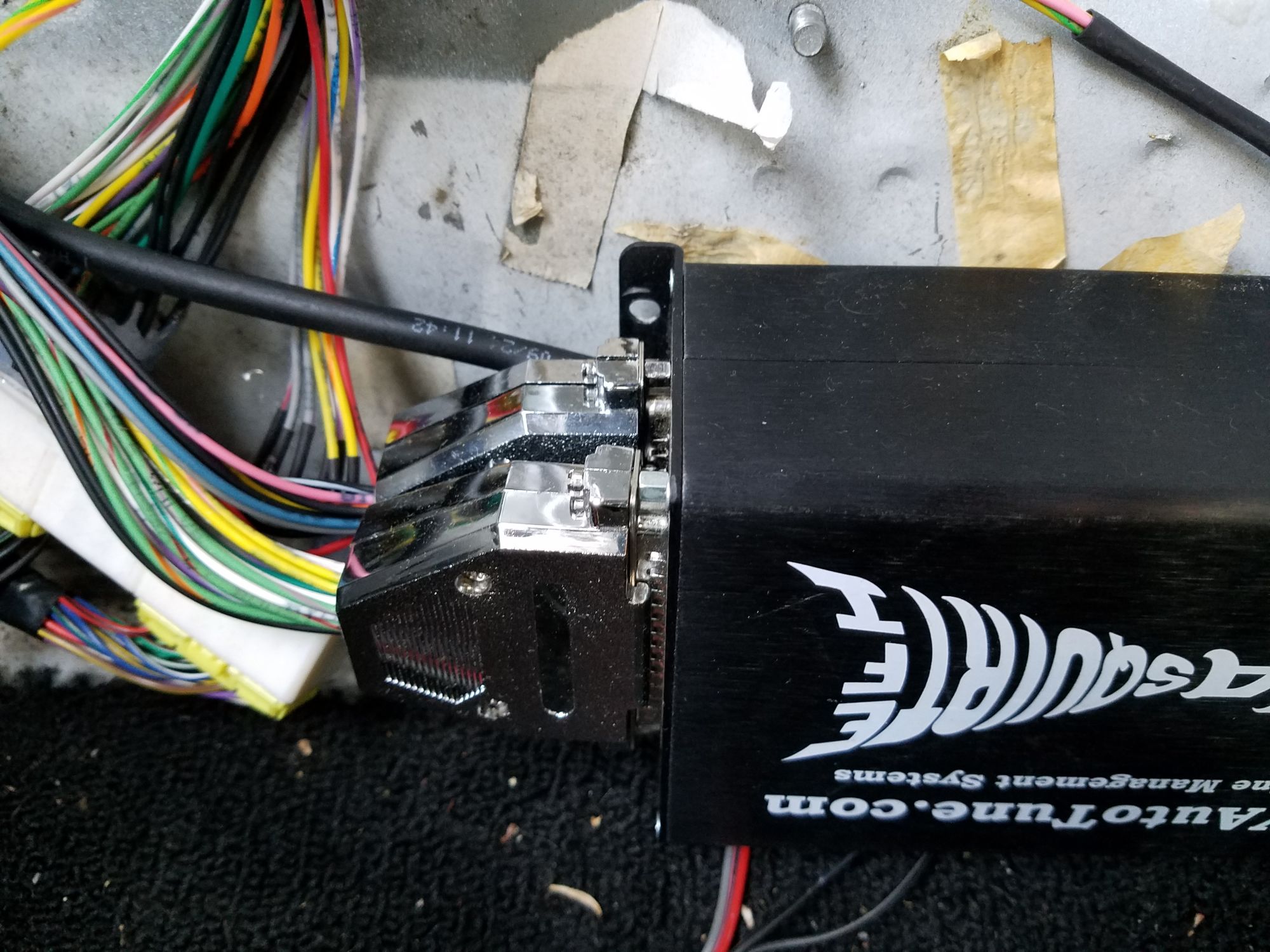
Brain build MS3 bought from Dwink, hooked into factory wiring, with vacuum line.
<br><br>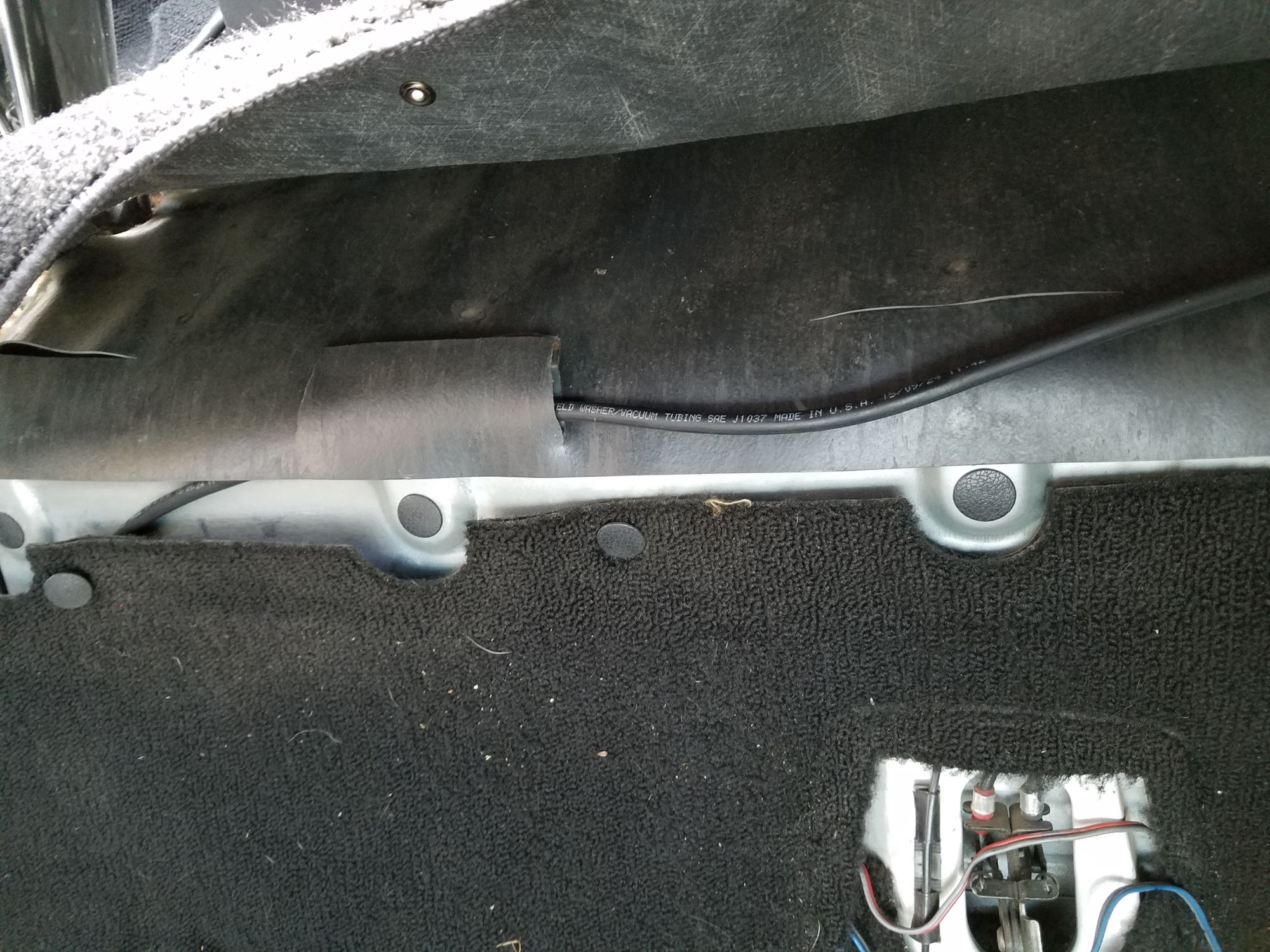
<br><br>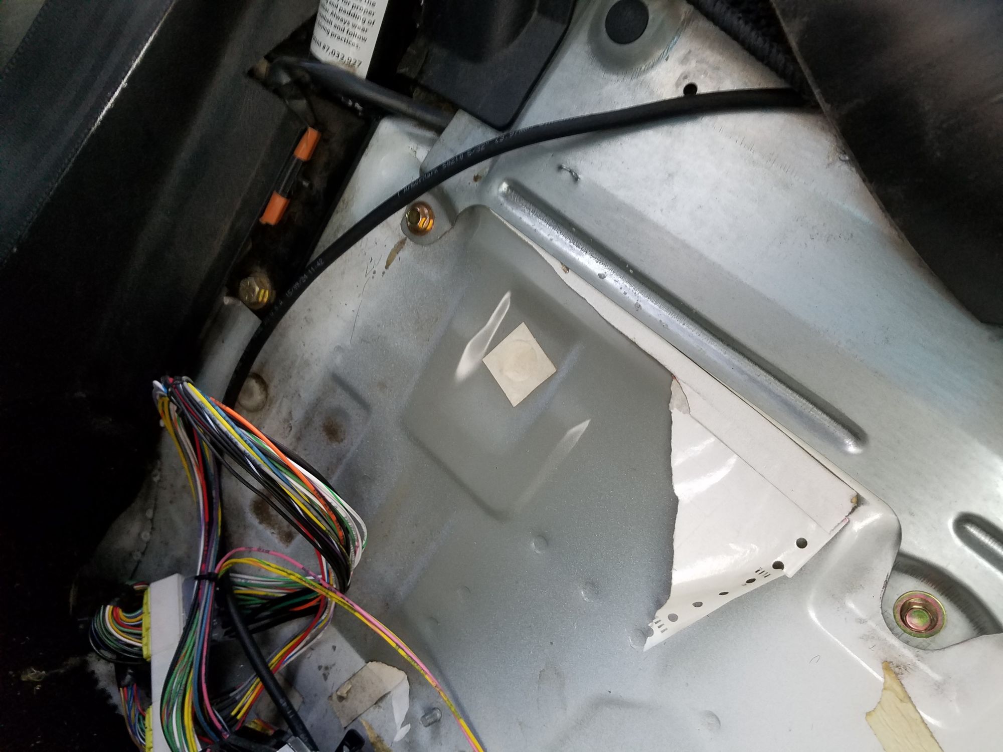
ecu spot isnt permanent, but I used some vacuum line to run it from the back of the passenger seat around the car lol.
<br><br>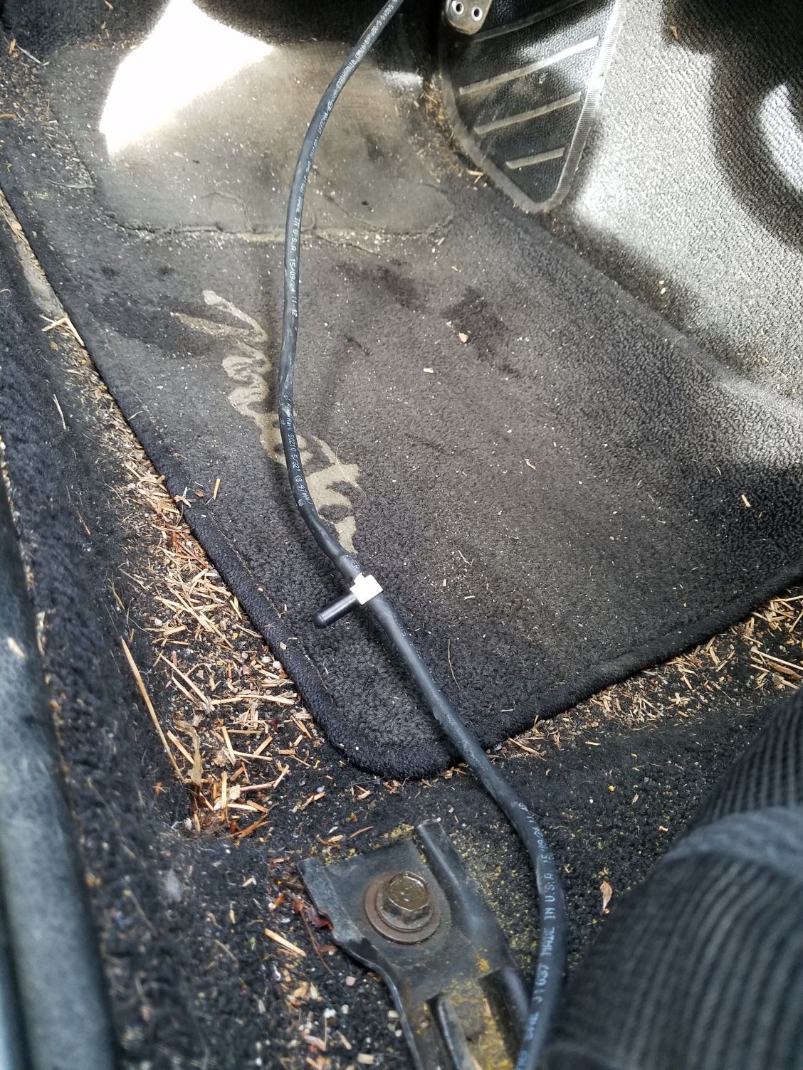
it runs around my driver seat and out of the firewall
<br><br>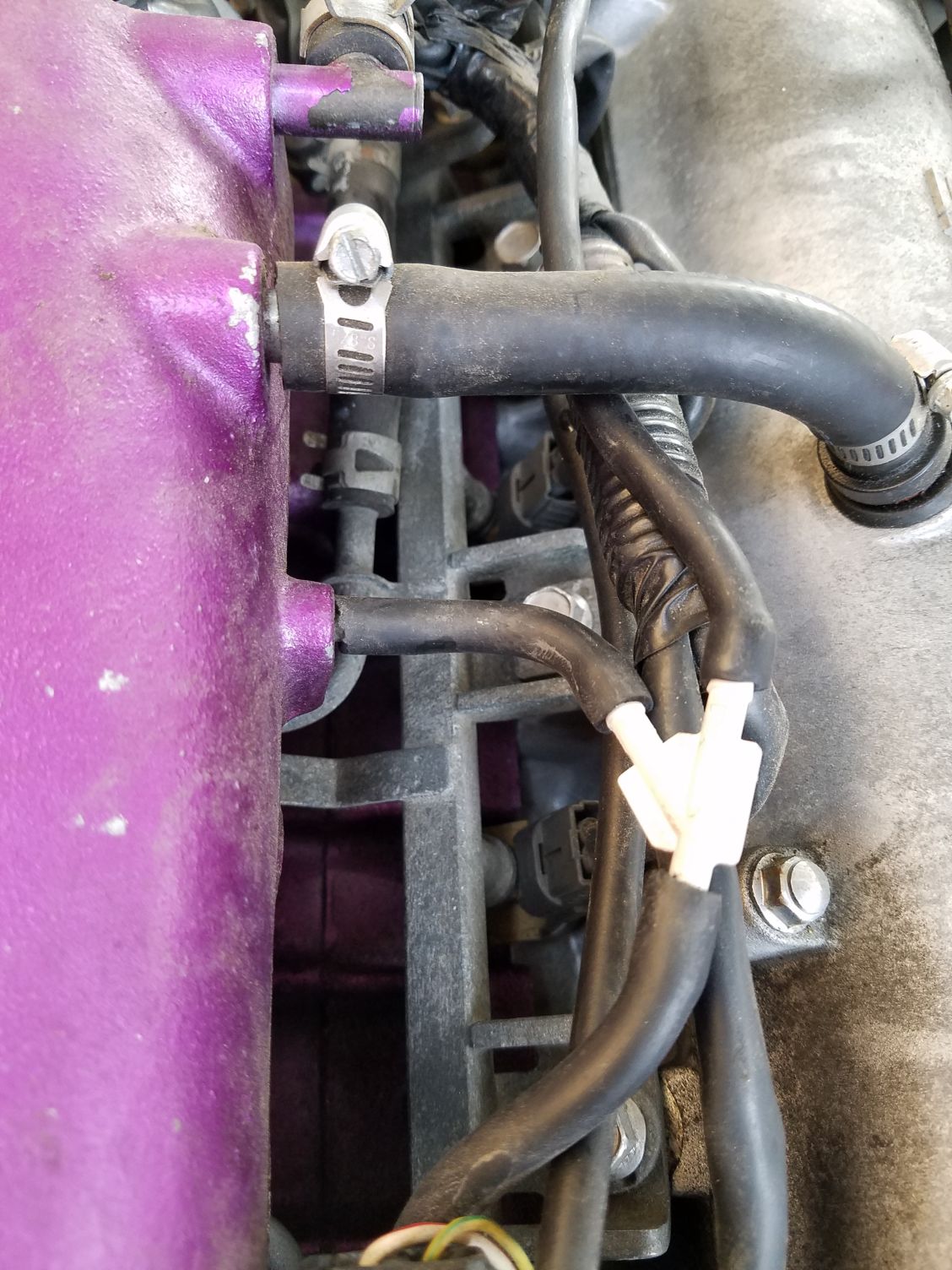
i tapped into the port that the instructions say to.
<br><br>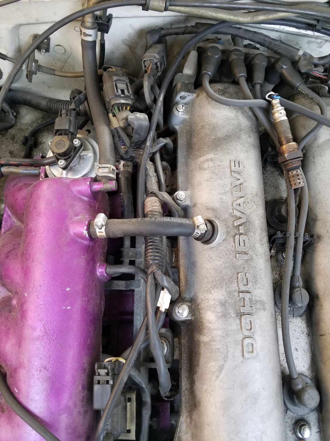
it fits decent for the time being
<br><br>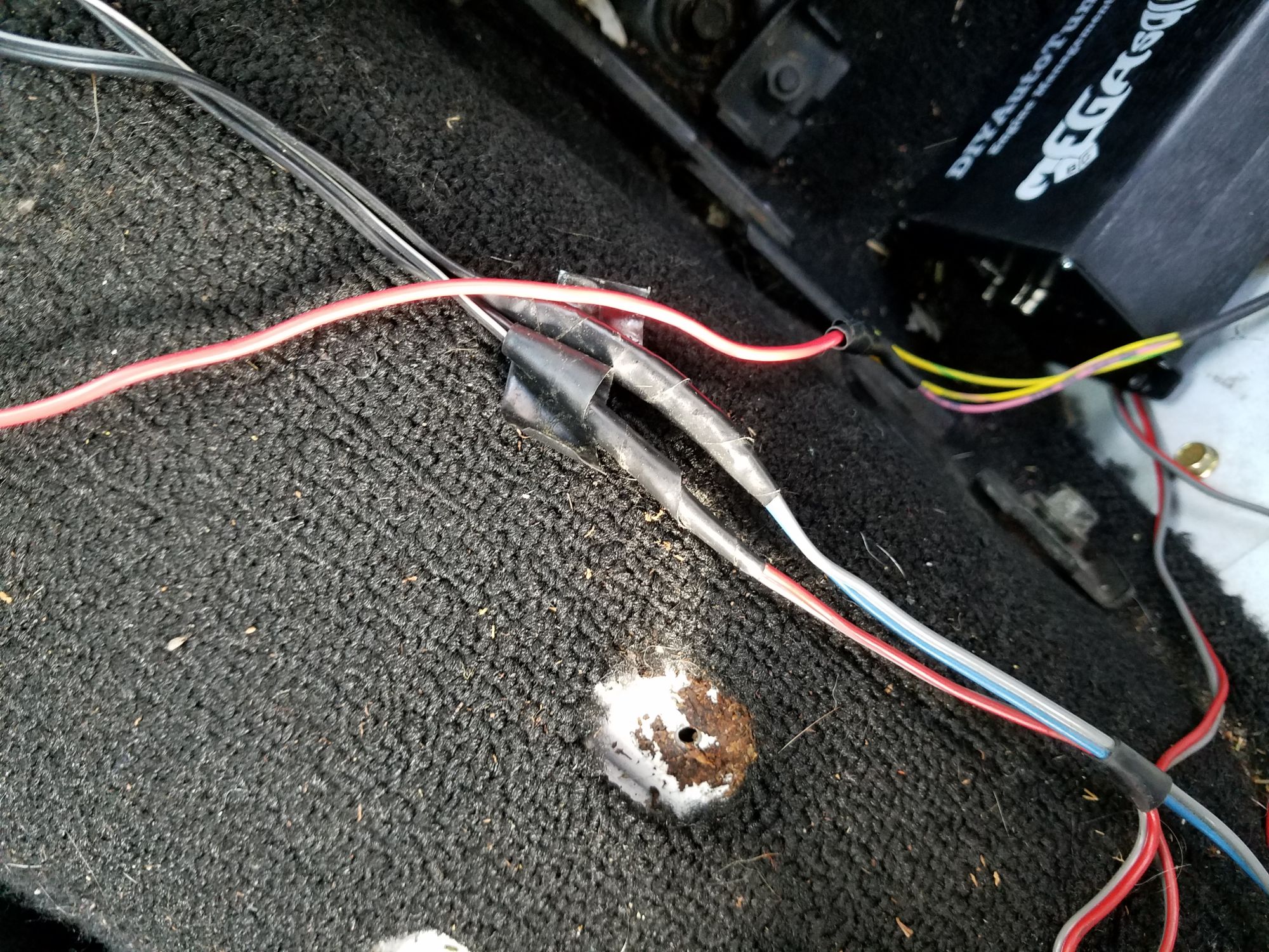
wideband analog wire from the ecu
<br><br>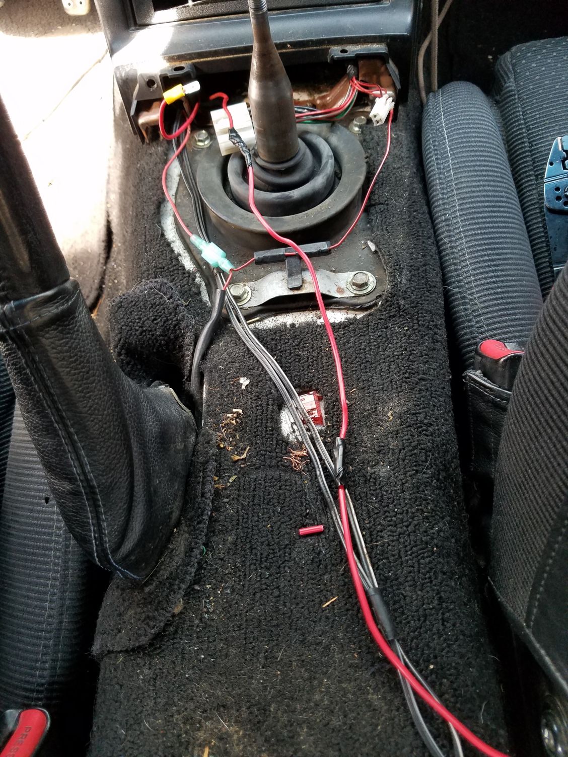
tracing the wideband analog wire
<br><br>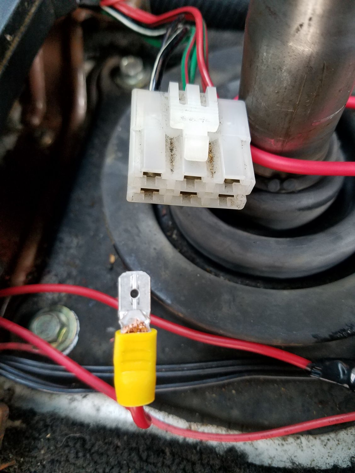
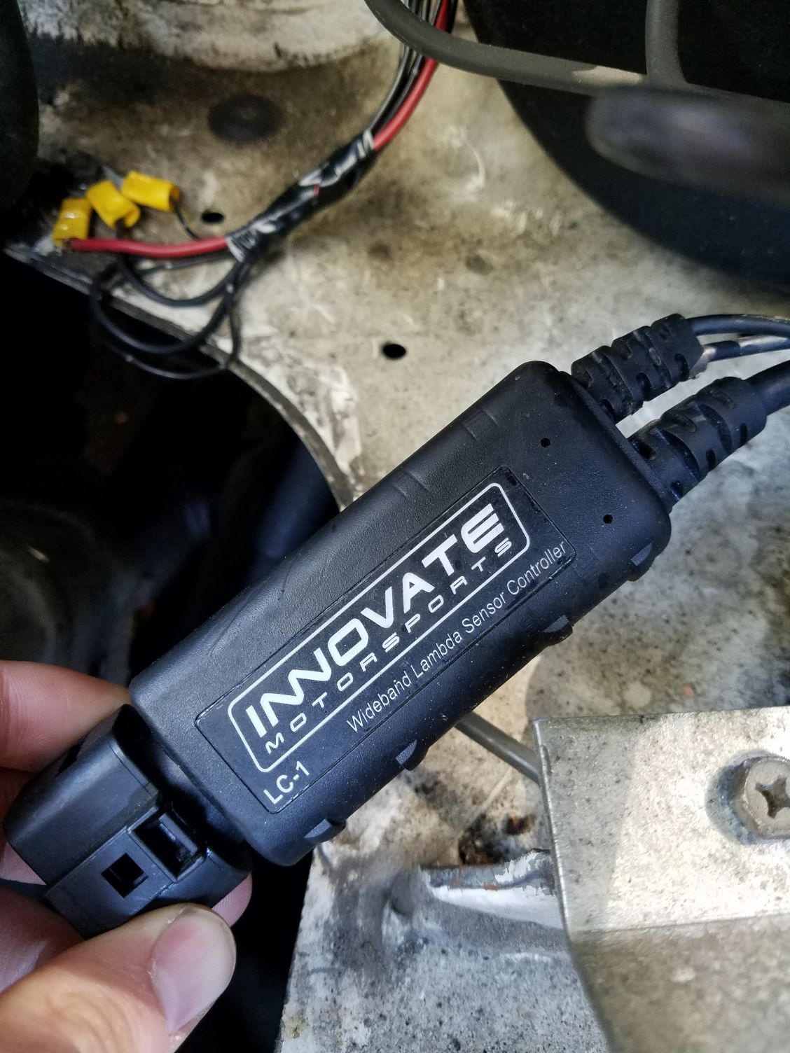
Male spade connector on the end of the LC-1 power wire.
<br><br>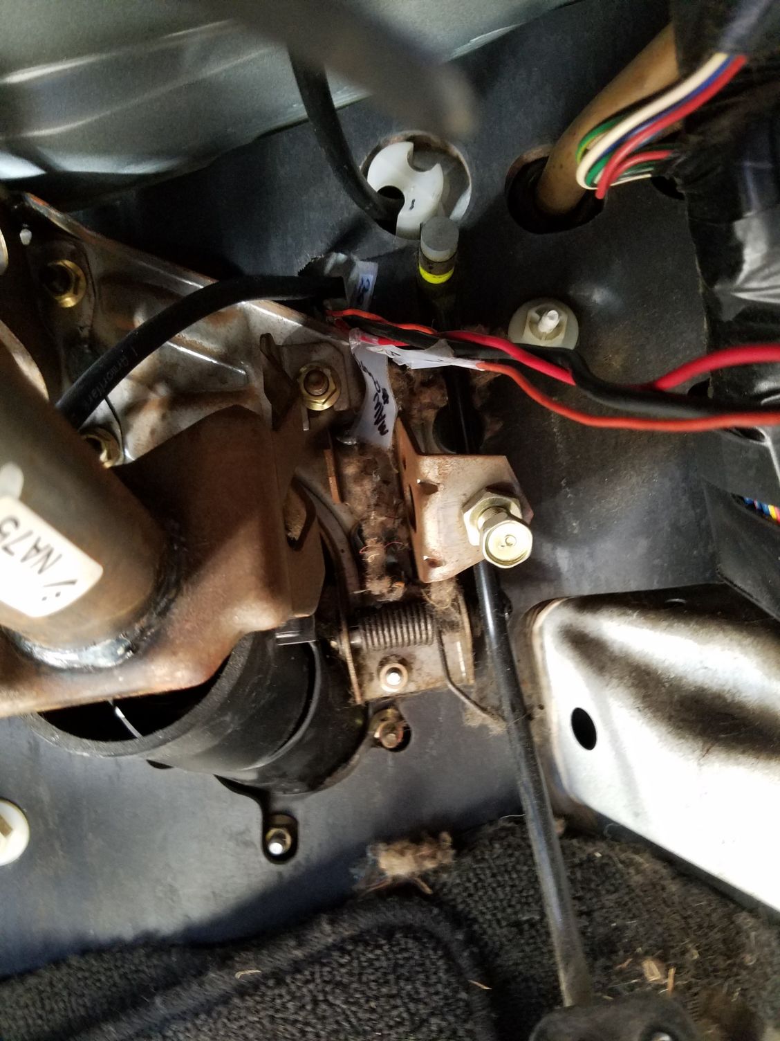
unknown gauge wires, and power/ecu wires in through the firewall
<br><br>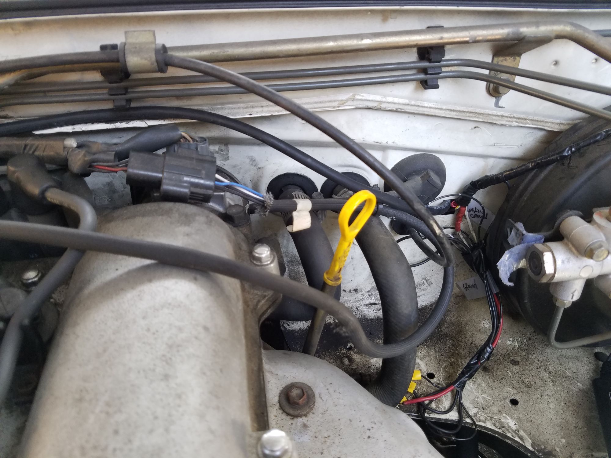
vacuum and wires through same hole. you can see my grounds right below.
<br><br>
instructions said if not using the dimming feature of the gauge then to ground that wire to the same spot as other grounds, so you can see I grounded everything here.<br><br> 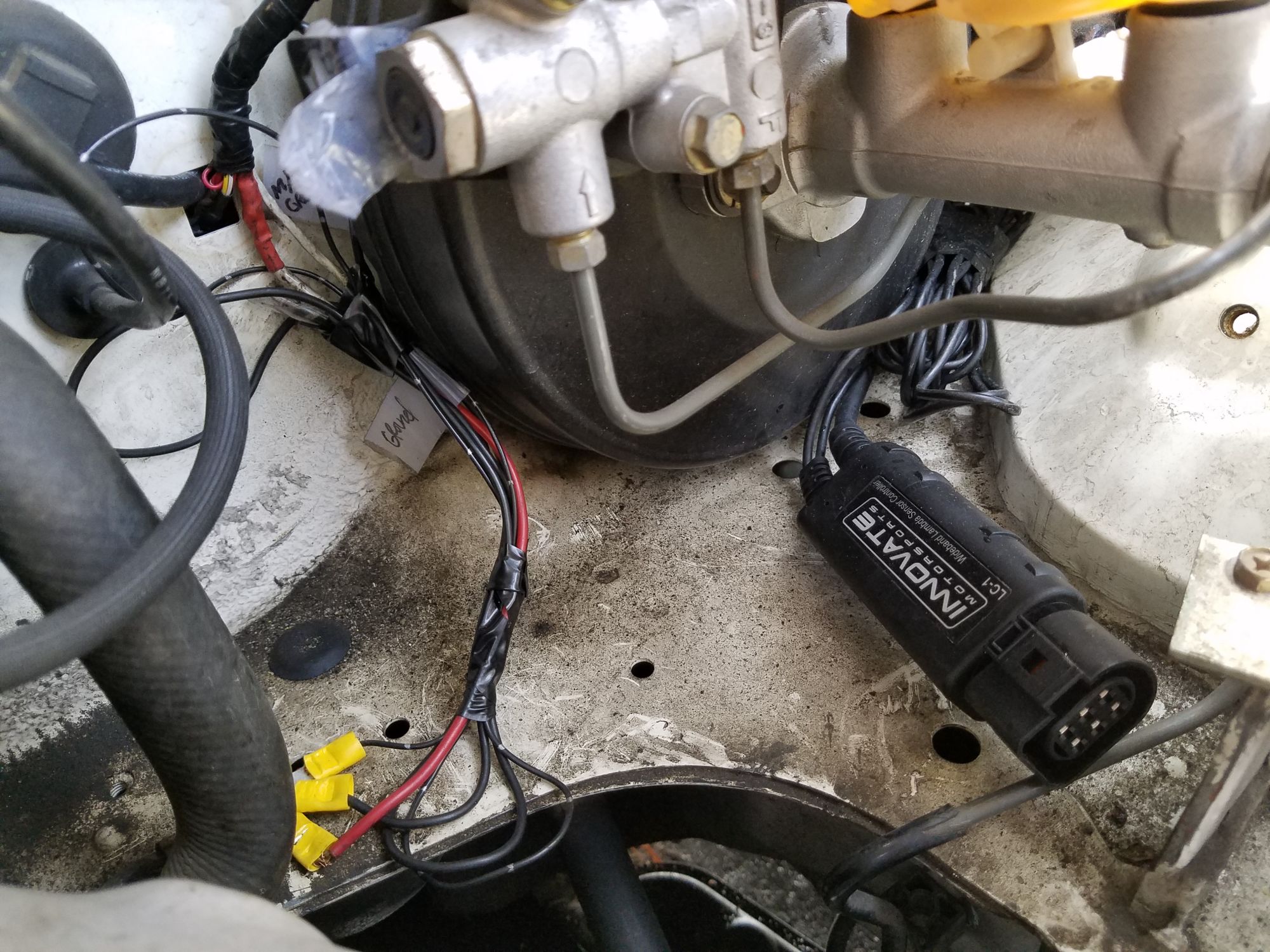
under the brake booster, the controller without the sensor hooked up, nice view of everything<br><br> 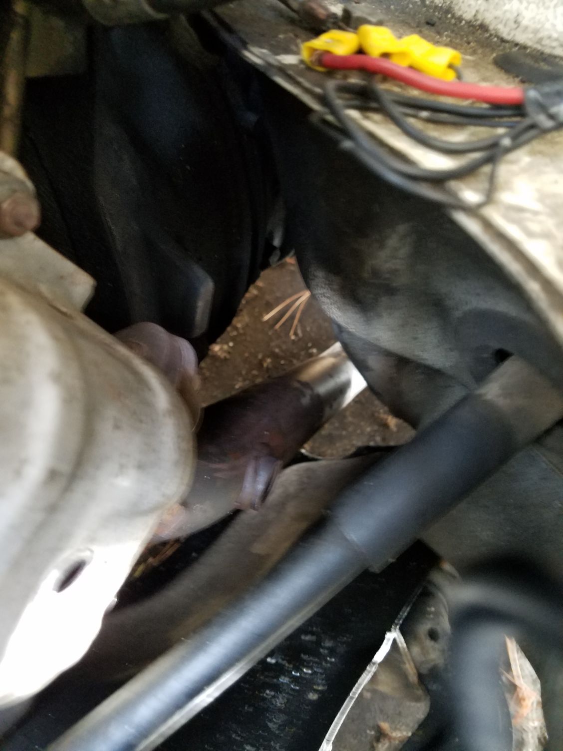
factory bung hole where I've remove the stock o2 sensor, cant put the wideband in until I get I know the gauge works.
<br><br>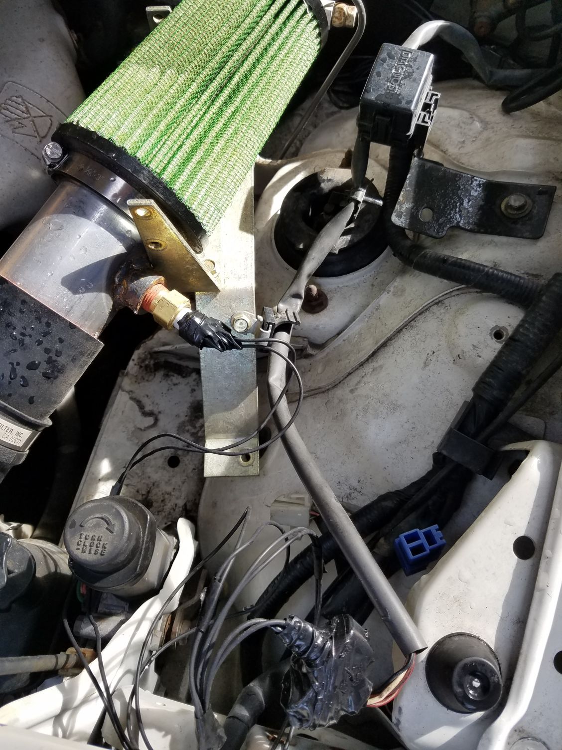
IAT wired into the 3&4 spots in the MAF sensor, taped up for weather proofing.<br><br> 
Someone said I could tap into this blue headlight wire for power for my wideband.
<br><br>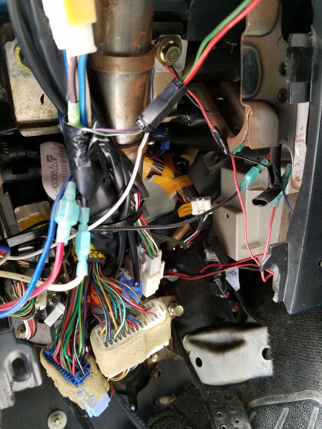
another person said to use this big blue wire on the left for the wideband power.<br><br> 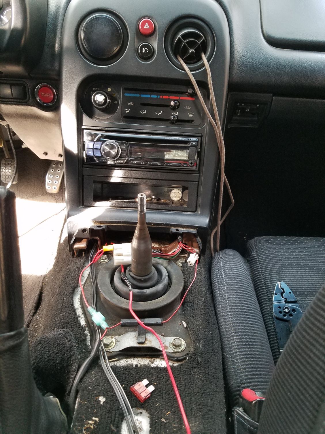
with everything hooked up and key switched to on, my radio comes on but the gauge doesn't light up and I'm expecting to see an error message at this point.
I took apart the loom and looked up innovates manuals and product manuals and figured out all of the wires in the loom. I attempted to hook it up in my car, but the gauge is not powering on.
I have also tried installing an MS3x built by braineack but purchased from a different forum member here at the same time as the wideband.
I have used what I think is a ridiculous length of vacuum line, at an attempt to not drill my firewall.
After hooking everything up according to manuals, and my research on this site and others I haven't been able to get power to the gauge.
I was hoping someone can look through these photos and help me figure out this out.
Thanks!
Brain build MS3 bought from Dwink, hooked into factory wiring, with vacuum line.
<br><br>
<br><br>
ecu spot isnt permanent, but I used some vacuum line to run it from the back of the passenger seat around the car lol.
<br><br>
it runs around my driver seat and out of the firewall
<br><br>
i tapped into the port that the instructions say to.
<br><br>
it fits decent for the time being
<br><br>
wideband analog wire from the ecu
<br><br>
tracing the wideband analog wire
<br><br>
Male spade connector on the end of the LC-1 power wire.
<br><br>
unknown gauge wires, and power/ecu wires in through the firewall
<br><br>
vacuum and wires through same hole. you can see my grounds right below.
<br><br>
instructions said if not using the dimming feature of the gauge then to ground that wire to the same spot as other grounds, so you can see I grounded everything here.<br><br>
under the brake booster, the controller without the sensor hooked up, nice view of everything<br><br>
factory bung hole where I've remove the stock o2 sensor, cant put the wideband in until I get I know the gauge works.
<br><br>
IAT wired into the 3&4 spots in the MAF sensor, taped up for weather proofing.<br><br>
Someone said I could tap into this blue headlight wire for power for my wideband.
<br><br>
another person said to use this big blue wire on the left for the wideband power.<br><br>
with everything hooked up and key switched to on, my radio comes on but the gauge doesn't light up and I'm expecting to see an error message at this point.

Reply
 0
0

0
03-14-2016, 02:34 PM
#2
Senior Member

Join Date: Aug 2007
Posts: 574
Total Cats: 44
holy wiring mess. did you do all that yourself? or was some of that pre-existing? Im not trying to be rude but that is **** and wont cut it. The lc1 led coming on at all? have you confirmed your power and ground sources with a multimeter?
Reply
0
0
03-14-2016, 02:39 PM
#3
Junior Member
Thread Starter
Join Date: Feb 2015
Location: South Lake Tahoe
Posts: 105
Total Cats: 1
lol, the loom was totally butchered. I did my best to unwrap it and find out what was done.
All I'm trying to do right now is figure out if this thing works, if it does, I am going to redo the loom and all of the connections, and permanently install it.
I have a multimeter, however I have no clue what to test, or what to switch my multimeter to lol. I am an electronics noob.
I havent checked the LED I'll do that right now. EDIT** just checked, and dont see an LED
I dont see an LED o nthe controller itself, and there is no LED wired into the loom
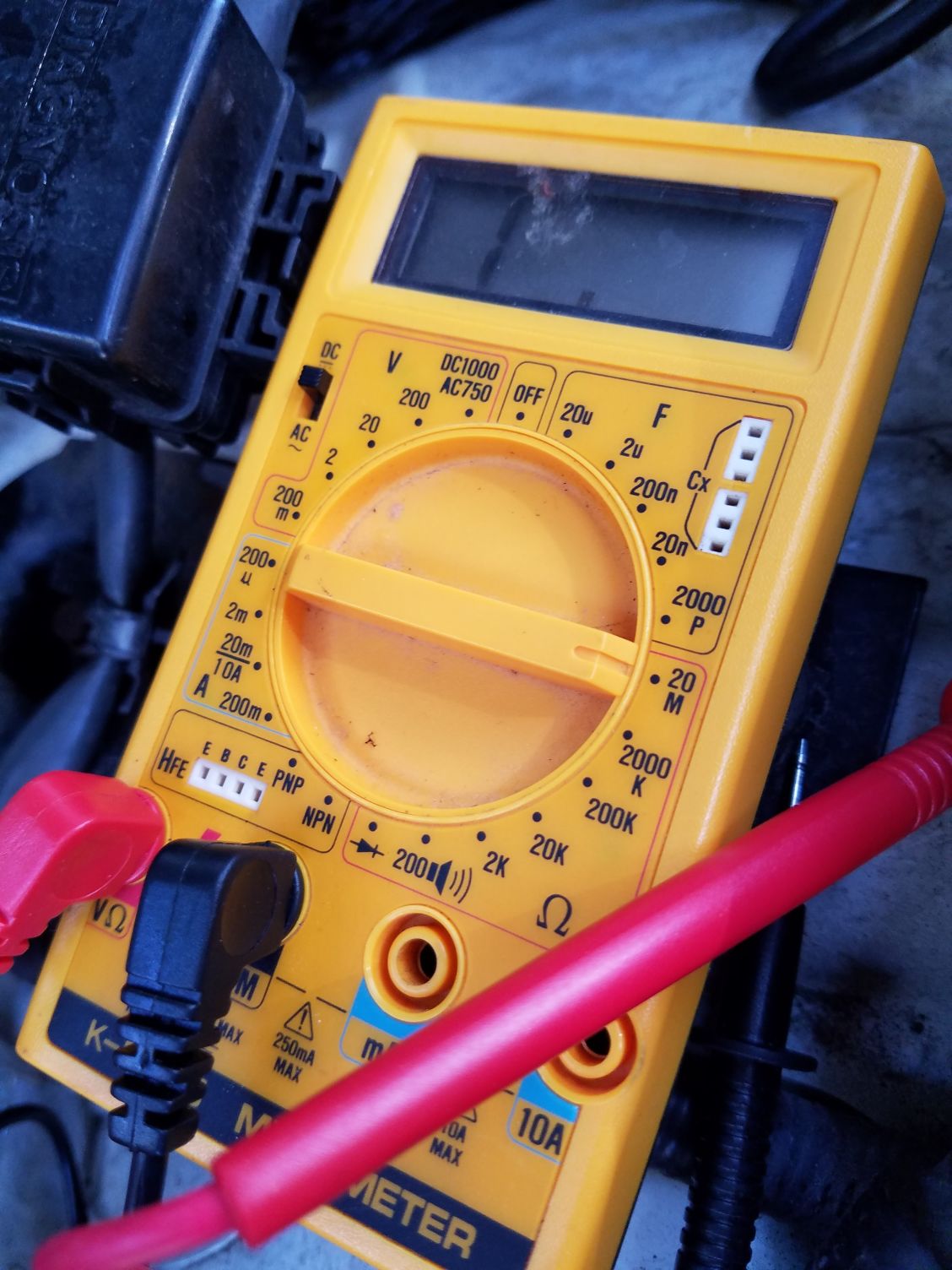
I don't know what to switch this to, or where I'm supposed to put the prongs.
Reply
0
0
03-14-2016, 03:19 PM
#4
Senior Member
Join Date: Aug 2007
Posts: 574
Total Cats: 44
ok, so if you do not know how to use a multimeter, you might not want to do this without adult supervision. i would atleast get on youtube or something and search for any videos showing you how to operate the meter. you are wanting to measure DC voltage on the power wire to the LC-1. Then measure resistance to ground on your ground connections.
see the instructions at this link for the LC-1 install info and note where it discusses hooking in the LED. http://www.innovatemotorsports.com/s...C-1_Manual.pdf
see the instructions at this link for the LC-1 install info and note where it discusses hooking in the LED. http://www.innovatemotorsports.com/s...C-1_Manual.pdf
Reply
0
0
 03-14-2016, 11:22 PM
#6
Junior Member
Thread Starter
Join Date: Feb 2015
Location: South Lake Tahoe
Posts: 105
Total Cats: 1
Yea lol hands on help would be nice. I'm in Tahoe California.
I did learn how to test grounds today, and check for continuity. Tomorrow in the light I'm going to try and test my grounds on the cable and go from there.
Reply
0
0
03-14-2016, 11:31 PM
#7
Senior Member

Join Date: May 2007
Location: Atlanta
Posts: 997
Total Cats: 156
So, while I do not approve this wiring overall - I will say that if you are using the power windows for a 12v source, you will need to add a fuse into the fusebox that's in the drivers side. That said.. ugh man. Don't burn down your car.
Also be aware that position is accessory powered - so it will turn off while cranking and back on when running.
Also be aware that position is accessory powered - so it will turn off while cranking and back on when running.
Reply
1
1
03-14-2016, 11:31 PM
#8

Using the same color wire for multiple circuits, will keep you in the dark. Forever.
Red wires leading to ground, is the holy grail of wrong. Black, black and white, are ground colors.
Go on ebay and buy some assorted color packs of 18-20g wire.
Buy a 40 dollar soldering iron, a sponge some Flux and silver solder, and some shrink tube.
Go on YouTube for some solder lessons. Your skills will be great in no time. I think.
Reply
0
0
03-15-2016, 08:02 AM
#9
Boost Czar


iTrader: (62)
Join Date: May 2005
Location: Chantilly, VA
Posts: 79,490
Total Cats: 4,079
I cringe every time i see someone install a WBo2 controller inside the engine bay and run wires through the firewall.
Who are these "people" that you are referring to for the worst wiring advice known to mankind?
Who are these "people" that you are referring to for the worst wiring advice known to mankind?
Reply
0
0
03-15-2016, 06:34 PM
#12
Junior Member
Thread Starter
Join Date: Feb 2015
Location: South Lake Tahoe
Posts: 105
Total Cats: 1
So, while I do not approve this wiring overall - I will say that if you are using the power windows for a 12v source, you will need to add a fuse into the fusebox that's in the drivers side. That said.. ugh man. Don't burn down your car.
Also be aware that position is accessory powered - so it will turn off while cranking and back on when running.
Also be aware that position is accessory powered - so it will turn off while cranking and back on when running.
Using the same color wire for multiple circuits, will keep you in the dark. Forever.
Red wires leading to ground, is the holy grail of wrong. Black, black and white, are ground colors.
Go on ebay and buy some assorted color packs of 18-20g wire.
Buy a 40 dollar soldering iron, a sponge some Flux and silver solder, and some shrink tube.
Go on YouTube for some solder lessons. Your skills will be great in no time. I think.
Red wires leading to ground, is the holy grail of wrong. Black, black and white, are ground colors.
Go on ebay and buy some assorted color packs of 18-20g wire.
Buy a 40 dollar soldering iron, a sponge some Flux and silver solder, and some shrink tube.
Go on YouTube for some solder lessons. Your skills will be great in no time. I think.
The ecu wire is red as well, and I grounded the gauge's dimming feature power wire which is red.
It is crazy messy, but it's all there, I'm hoping it works.
Those "people" are users of this site. I found old posts of people discussing where they wired in the LC-1's power wire. After searching, I asked, because obviously, I didn't take their advice, and I went with the male spade connector to power window switch as there were more posts of people doing that with success.
I have been at work all day so I have still yet to test my grounds, but I'll be doing that tonight.
Reply
0
0
03-16-2016, 02:02 PM
#15
Senior Member
Join Date: Aug 2007
Posts: 574
Total Cats: 44
in the past i have used the air bag power wire over near the steering column. That is on cars that i have changed the steering wheel and no longer use air bags. since the air bag power fuse is no longer supplying voltage to the module, i used it. Thats just a thought.
Reply
0
0
03-16-2016, 03:02 PM
#17
Boost Czar
iTrader: (62)
Join Date: May 2005
Location: Chantilly, VA
Posts: 79,490
Total Cats: 4,079
if you're going to use any power, i'd suggest a red/white one; the same the ECU uses.
i'll update this post with a better response.
I DO like the idea of adding a 5A fuse on the wideband power.
i'll update this post with a better response.
I DO like the idea of adding a 5A fuse on the wideband power.
Reply
0
0
03-19-2016, 04:47 PM
#18
Junior Member
Thread Starter
Join Date: Feb 2015
Location: South Lake Tahoe
Posts: 105
Total Cats: 1
So I tested all of my grounds, and they all worked.
I had a buddy come over who knows more about the electrical stuff than I do. I tested power, and after all of our work, he seemed to think it was the gauge itself that was broken. Here are a few more pictures of my updated progress.
I also cut through the layer of dynamax protecting my A/C line firewall hole, and routed the ECU vacuum line correctly.
Once again, I'm just trying to test if this thing works, if it doesn't I'll buy a new one. If I need to route power differently, I will, or if i need the fuse to test for power to the gauge I will go put a fuse in.
Thanks for all the help so far guys.
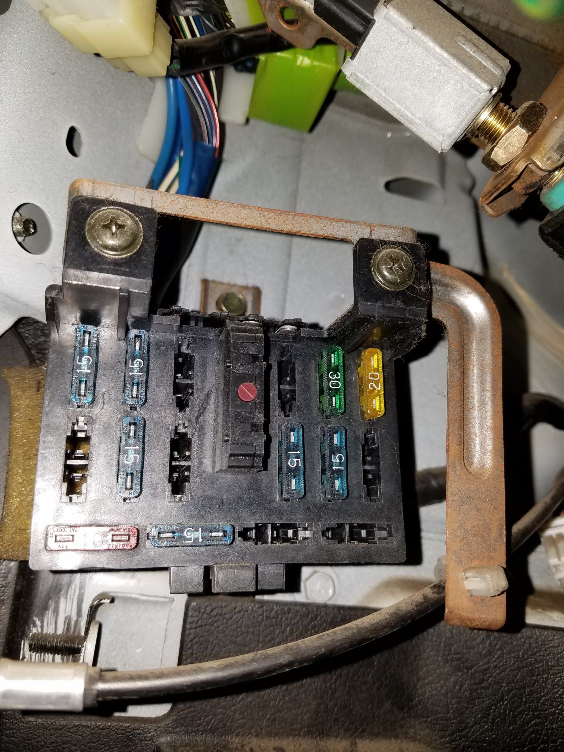
I dont have a cover for my fuse box, my friend said I should be able to see power on the gauge without a fuse in here, is he wrong?
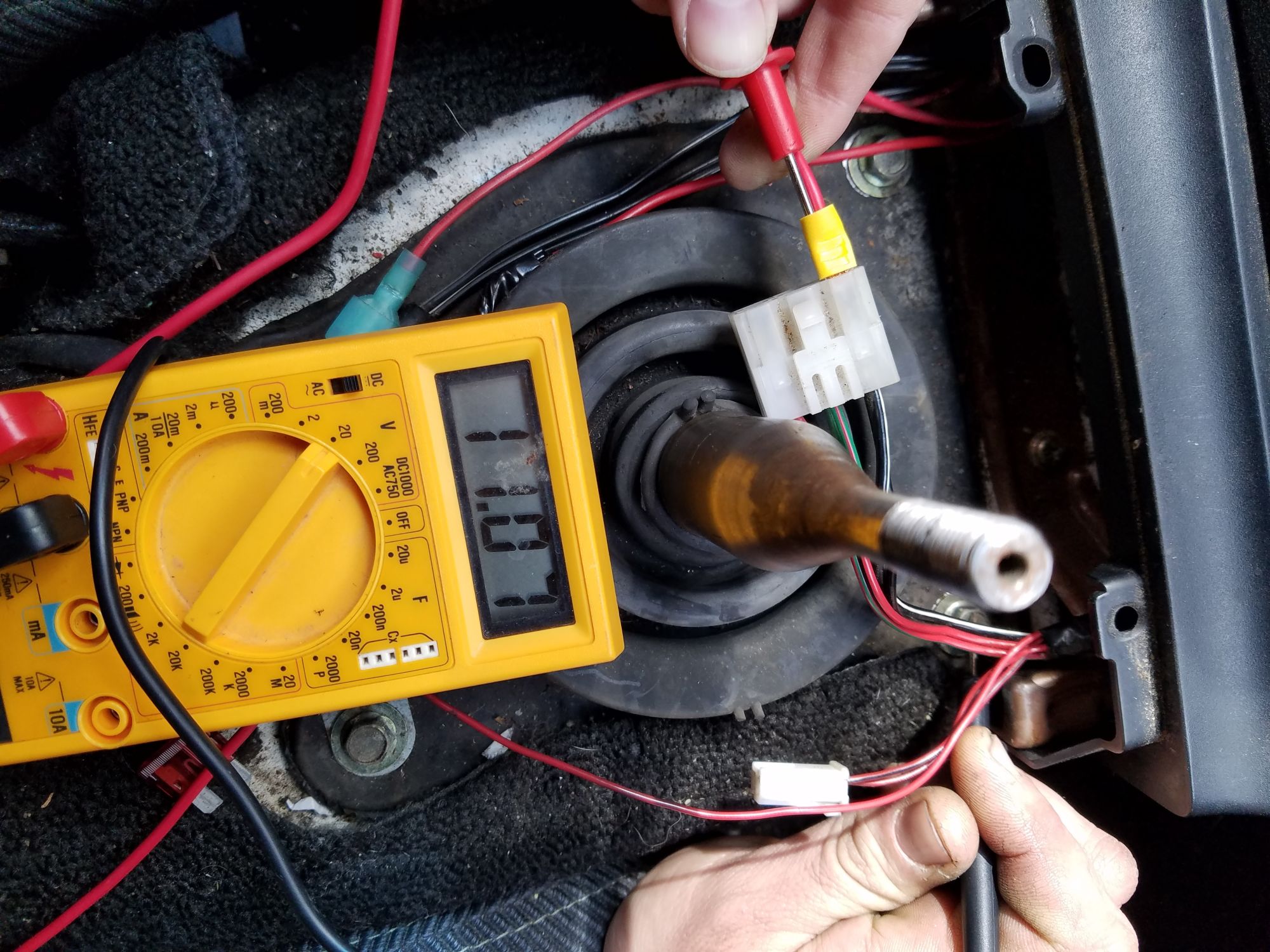
with the key on.
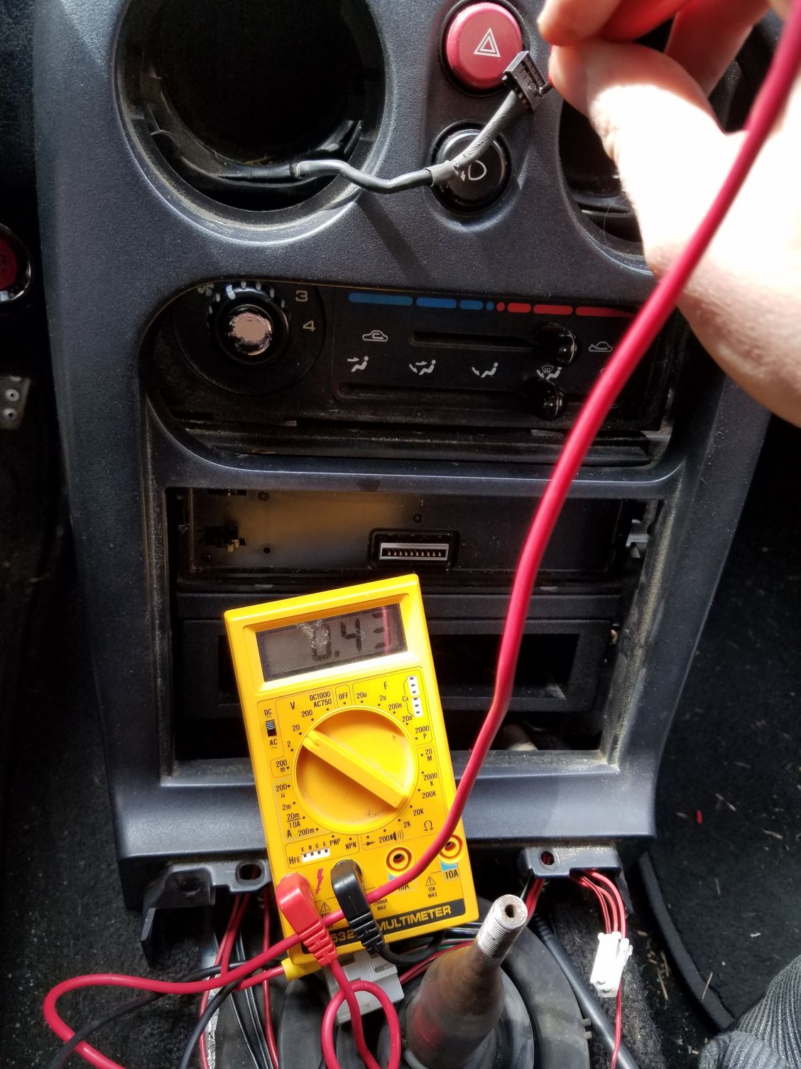
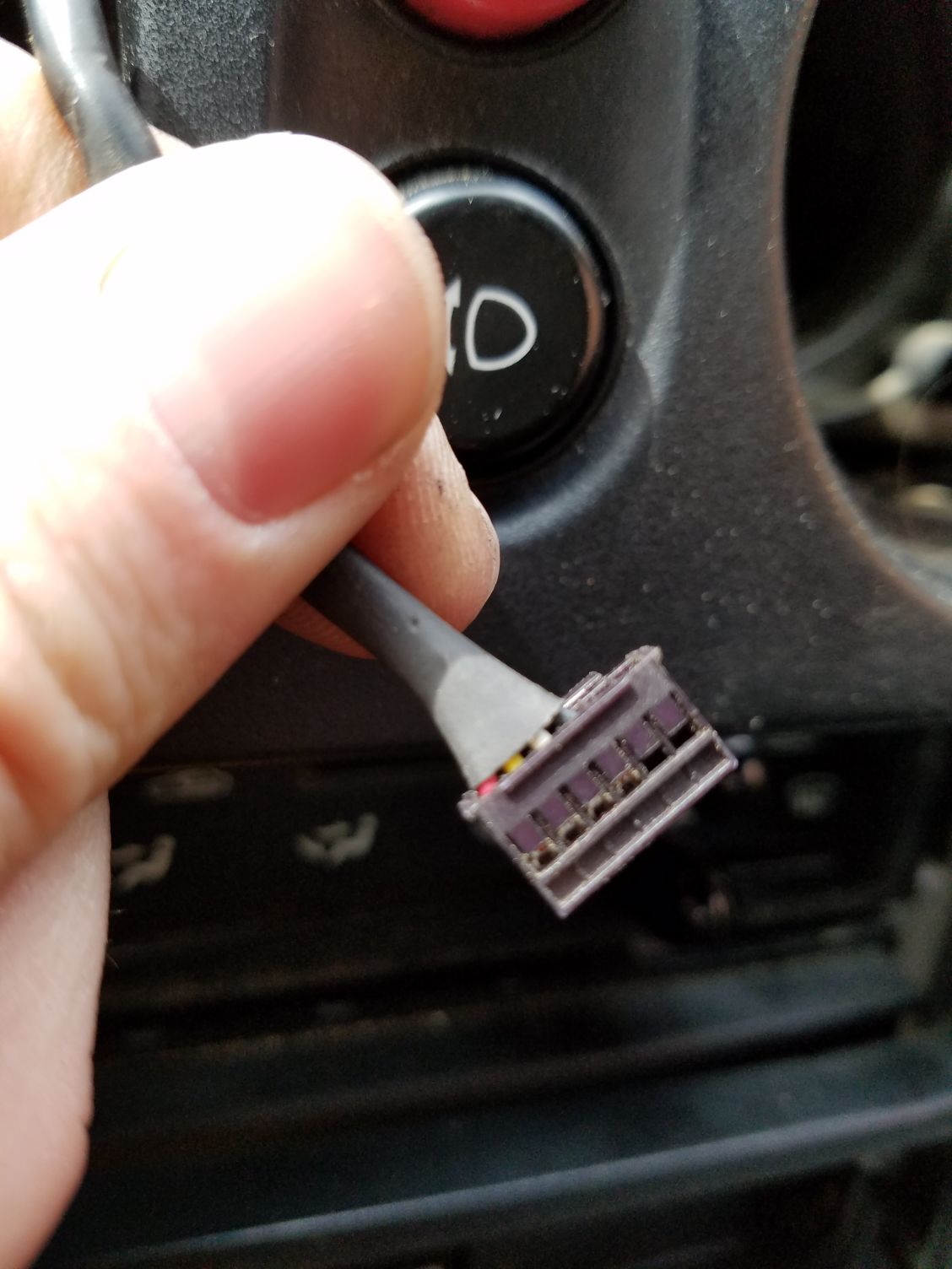
this is the reading from the power wire on the connector to the back of the gauge.
I tested the red wire
I had a buddy come over who knows more about the electrical stuff than I do. I tested power, and after all of our work, he seemed to think it was the gauge itself that was broken. Here are a few more pictures of my updated progress.
I also cut through the layer of dynamax protecting my A/C line firewall hole, and routed the ECU vacuum line correctly.
Once again, I'm just trying to test if this thing works, if it doesn't I'll buy a new one. If I need to route power differently, I will, or if i need the fuse to test for power to the gauge I will go put a fuse in.
Thanks for all the help so far guys.
I dont have a cover for my fuse box, my friend said I should be able to see power on the gauge without a fuse in here, is he wrong?
with the key on.
this is the reading from the power wire on the connector to the back of the gauge.
I tested the red wire
Reply
0
0


