turbo manifold design
 08-02-2010, 07:14 PM
#101
Former Vendor

iTrader: (31)

Join Date: Nov 2006
Location: Sunnyvale, CA
Posts: 15,442
Total Cats: 2,099
Timmy, if the valve seals I just ordered fix my blowby problems the manifold timetable may get moved up quite a bit.
Jason, I think the fatal flaw comes in the pressure itself. We are measuring boost pressure in the plenum, but not at the ports. Make the manifold less restrictive (throat angles, plenum design and about a bajillion other things) and the average pressure at the back of the intake valve will come closer and closer to the plenum pressure.
Mass flow rate should increase from one of three things: RPM, the size of the turbo (volume), and the pressure ratio. IM restriction won't show up in smaller turbos, low RPMs or at low boost pressures because the mass flow rate is low. As the mass flow rate continues to increase, the intake manifold will become a greater and greater restrictor because the pressure drop across the manifold grows in relation to air density AND velocity.
This is why we see most of the benefits of aftermarket IMs at high RPM and high power levels (high mass flow rates) - not only is the mass flow rate increasing, but in order to increase that mass flow rate and maintain the same area (and pressure, aka with a larger turbo) you must ALSO increase the velocity of the air, which will produce an exponentially increasing pressure restriction as the mass flow rate requirement goes up with RPM.
This doesn't explain why I picked up 3psi and no torque, though, because there's no increased velocity requirement with the increased pressure. :( I will try and scrounge up the timing map.
pressure drop = mvk/2a
where
m = mass flow rate
v = velocity
k = loss coefficient (lol, if you want a life-long project calculate this for an intake manifold)
a= area
The TIP stuff is very interesting. What kind of gauge are you using to take those measurements, Jason?

Reply
 0
0

0
08-02-2010, 07:32 PM
#102

According to the specs it is a WRC focus and the turbo is a TR30R or a custom IHI unit. I�m guessing that is an IHI unit. Note also it has to suck through a restrictor. This is very bad for turbo reliability because the pressure ratio is increased dramatically for a given boost ratio.
Bob
Bob
PR is sky high as you say. The turbo has a low-flow, high PR compressor stage since the flow literally flatlines once the restrictor chokes midway thru the rev range.
Exh manifolds -- transient response is a tradeoff of exh man volume and pulse recovery. Pulse energy decays as a function of exh man volume.
When boost recovery / transient response / boost threshold is as important as high power (street/roadcourse use; a lot of throttle- and rpm-transients), you want short primaries for low volume. You also want equal pressure drop among primaries (note that this is not necessarily the same thing as equal length). This last bit also means you don't want a bunch of super tight radius elbows comprising all of your primaries...
If you're building a land speed record car, go for a tuned primary length (i.e. long runner sexytime) header. Here, pulse recovery is less critical than optimizing peak power.
Reply
0
0
08-02-2010, 07:45 PM
#103
Individual cyl trims to balance out the a/f and optimize ign timing across all four holes help band-aid this limitation.
Reply
0
0
 08-03-2010, 12:57 AM
#106
Elite Member

Join Date: Jul 2005
Location: Anacortes, WA
Posts: 2,478
Total Cats: 144
It's a TR30R.
PR is sky high as you say. The turbo has a low-flow, high PR compressor stage since the flow literally flatlines once the restrictor chokes midway thru the rev range.
Exh manifolds -- transient response is a tradeoff of exh man volume and pulse recovery. Pulse energy decays as a function of exh man volume.
When boost recovery / transient response / boost threshold is as important as high power (street/roadcourse use; a lot of throttle- and rpm-transients), you want short primaries for low volume. You also want equal pressure drop among primaries (note that this is not necessarily the same thing as equal length). This last bit also means you don't want a bunch of super tight radius elbows comprising all of your primaries...
If you're building a land speed record car, go for a tuned primary length (i.e. long runner sexytime) header. Here, pulse recovery is less critical than optimizing peak power.
Bob
Reply
0
0
08-03-2010, 01:44 AM
#107
Elite Member
Join Date: Jul 2005
Location: Anacortes, WA
Posts: 2,478
Total Cats: 144
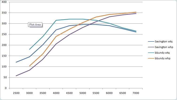
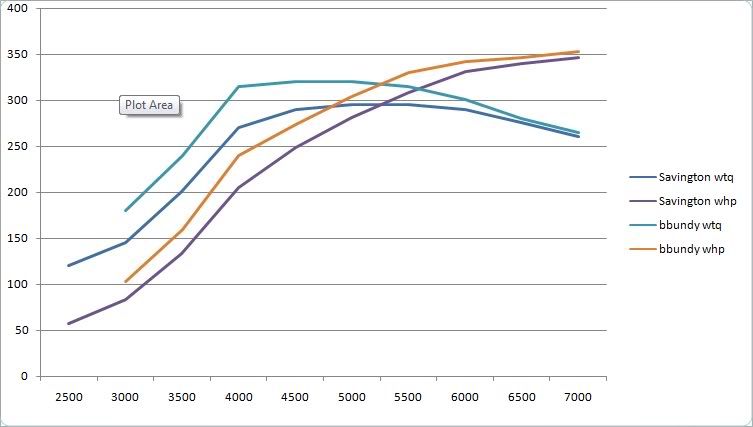
Here is my dyno run. Run was done at 17psi.
2.0L stroker
99 ported head oversized valves
94 intake manifold gutted of EGR with mild port with a 99 flange welded on.
Equal length fairly long small diameter turbo manifold
3” exhaust turbo exit flange back.
Note: crosses 300ft-lb at 3800 rpm and stays above 300ft-lbs till 6250 rpm pretty fat usable torque range for this much power.
FWIW on the Flyin Miata dyno at altitude corrected the torque plateau was shifted a little more than 500 rpm to the right and the numbers were 397hp 373 ft lbs. I didn’t believe the numbers were that high.
Bob
Reply
0
0
08-03-2010, 01:58 AM
#108
Junior Member

Join Date: Apr 2008
Posts: 349
Total Cats: -2
One thing I've seen is the collector seems to make a big difference. I've seen only the collector changed with astounding results. Unfortunately, the packaging in the Miata doesn't give us a ton of choices. Ramshorn has more than other options. I'm curious to see the Tim/Sav results. Wanting to keep weight down, the favorable results obtained by others, and a desire to have the whole system fly under the radar, or at least under some OE-looking heat shield, points me toward Absurdflow style. I've tried to think of some smarter way to do the merge into the turbine housing and can't.
The inside perimeter of a 1.5-in Sch. 10 weld-el is only 4mm more than the inside perimeter of a port that's matched to the outline of the OE gasket.
Okay, add 1.50-in vs. 1.25-in weld els to the comparison matrix...
The inside perimeter of a 1.5-in Sch. 10 weld-el is only 4mm more than the inside perimeter of a port that's matched to the outline of the OE gasket.
Okay, add 1.50-in vs. 1.25-in weld els to the comparison matrix...
Reply
0
0
08-03-2010, 01:59 AM
#109
Former Vendor
iTrader: (31)
Join Date: Nov 2006
Location: Sunnyvale, CA
Posts: 15,442
Total Cats: 2,099
It's very interesting that both of our charts basically plummet after 6200rpm, Bob. You can see the Honda IM gains in the 5000-6000 range, where I lose ~5tq and you lose ~20tq. You can also see where the stock IM might gain a little bit on the Honda IM, from like 4000-4500. Beyond 6k, though, we both tank, even though our setups are so different. So what do we both have in common that's causing the massive torque drop past 6k? Are you still on stock camshafts?
Reply
0
0
08-03-2010, 02:40 AM
#110

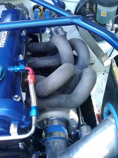
Here is a pic I snagged about a year ago. After seeing 1.5" pipe for so long, the 1.25" pipe looks really small but I definitely see how its more appropriately sized for the job. I dont know why I never noticed the different diameter in manifold plumbing until tonight.
Reply
0
0
08-03-2010, 02:59 AM
#111
Elite Member
Join Date: Jul 2005
Location: Anacortes, WA
Posts: 2,478
Total Cats: 144
It's very interesting that both of our charts basically plummet after 6200rpm, Bob. You can see the Honda IM gains in the 5000-6000 range, where I lose ~5tq and you lose ~20tq. You can also see where the stock IM might gain a little bit on the Honda IM, from like 4000-4500. Beyond 6k, though, we both tank, even though our setups are so different. So what do we both have in common that's causing the massive torque drop past 6k? Are you still on stock camshafts?
Bob
Reply
0
0
08-03-2010, 03:37 AM
#112
Elite Member
Join Date: Jul 2005
Location: Anacortes, WA
Posts: 2,478
Total Cats: 144
One thing I've seen is the collector seems to make a big difference. I've seen only the collector changed with astounding results. Unfortunately, the packaging in the Miata doesn't give us a ton of choices. Ramshorn has more than other options. I'm curious to see the Tim/Sav results. Wanting to keep weight down, the favorable results obtained by others, and a desire to have the whole system fly under the radar, or at least under some OE-looking heat shield, points me toward Absurdflow style. I've tried to think of some smarter way to do the merge into the turbine housing and can't.
The inside perimeter of a 1.5-in Sch. 10 weld-el is only 4mm more than the inside perimeter of a port that's matched to the outline of the OE gasket.
Okay, add 1.50-in vs. 1.25-in weld els to the comparison matrix...
The inside perimeter of a 1.5-in Sch. 10 weld-el is only 4mm more than the inside perimeter of a port that's matched to the outline of the OE gasket.
Okay, add 1.50-in vs. 1.25-in weld els to the comparison matrix...
The second picture is a shorty manifold I built for a B6t. I was also surprised it didn�t seem to spool as well as I expected.
Bob
Reply
0
0
 08-03-2010, 04:33 PM
#116
straightlinespecialties

Join Date: Jan 2009
Posts: 26
Total Cats: 0
A manifold w/ a true merge collector will outperform one w/o in both spool and power theres no question about that. We've done some back to back testing in the evo market that back both statements above.
Im running a 1.25" runner manifold as well. The debate between 1.25" and 1.5" varies drastically, on the Hondas the 1.25 chokes up pretty bad on the evo is under 10whp and 200rpm spool. We've designed setups for other custoemrs specifically in the road race industry that has gained heavy mid ramnge and are making 700+whp and 600+ trq.
Im running a 1.25" runner manifold as well. The debate between 1.25" and 1.5" varies drastically, on the Hondas the 1.25 chokes up pretty bad on the evo is under 10whp and 200rpm spool. We've designed setups for other custoemrs specifically in the road race industry that has gained heavy mid ramnge and are making 700+whp and 600+ trq.
Reply
0
0
08-03-2010, 10:05 PM
#117
Junior Member
Join Date: Apr 2008
Posts: 349
Total Cats: -2
Im running a 1.25" runner manifold as well. The debate between 1.25" and 1.5" varies drastically, on the Hondas the 1.25 chokes up pretty bad on the evo is under 10whp and 200rpm spool. We've designed setups for other custoemrs specifically in the road race industry that has gained heavy mid ramnge and are making 700+whp and 600+ trq.
Im running a 1.25" runner manifold as well. The debate between 1.25" and 1.5" varies drastically. On the Hondas, the 1.25 chokes up pretty bad. On the Evo, the loss is less than 10whp at the top end and spool is 200 rpm sooner. <With what turbo?> We've designed setups for other customers specifically in the road race industry that have gained heavy mid range and are making 700+whp and 600+ trq. <Gained by going from 1.25 to 1.5, or by going from 1.5 to 1.25?>
Reply
0
0
08-04-2010, 12:00 PM
#119
Elite Member
Join Date: Jul 2005
Location: Anacortes, WA
Posts: 2,478
Total Cats: 144
I suck at written English and spelling myself even though it is the only language I know. But I would really like to know if some of these guys have really useful input rather than trying to figure out what they are saying and having trouble doing it due to poor writing.
Bob
Reply
0
0


