How to drive an NB speedo without a speed sensor
 09-02-2015, 12:04 PM
#2
SADFab Destructive Testing Engineer


Thread Starter
iTrader: (5)
Join Date: Apr 2014
Location: Beaverton, USA
Posts: 18,642
Total Cats: 1,866
<p>So this came from @yank's need for a speedo. He has an FE3 swap with an rx7 transmission, and the exhaust is in the way of the transmission speed sensor. Its in an NA, which has a cable driven speedo, so instead we switched to an NB cluster which has an electrically driven speedo.</p><p>The MS3 has provisions for taking a square wave in as a speed sensor, and can also output a square wave.</p><p>The ABS sensor we used outputs a VR signal much like the NB sensor, but at a different rate. So the plan became abs sensor -> vr conditioner -> megasquirt -> speedo.</p><p>Last night when I pulled out my spare cluster I realized that the cluster wanted a vr signal to drive it, and thought we were fucked. But I said screw it and hooked up the square wave, and it worked.</p><p>Now we just need to wire it into the megasquirt and do some math.</p><p> </p><p> </p><p> </p><p> </p>

Reply
 0
0

0
 11-09-2015, 04:49 PM
#5
SADFab Destructive Testing Engineer
Thread Starter
iTrader: (5)
Join Date: Apr 2014
Location: Beaverton, USA
Posts: 18,642
Total Cats: 1,866
Can someone double check this.
We have the ABS sensor providing a speed signal to the MS3.
We have powered the speedo using a 0-5v square wave.
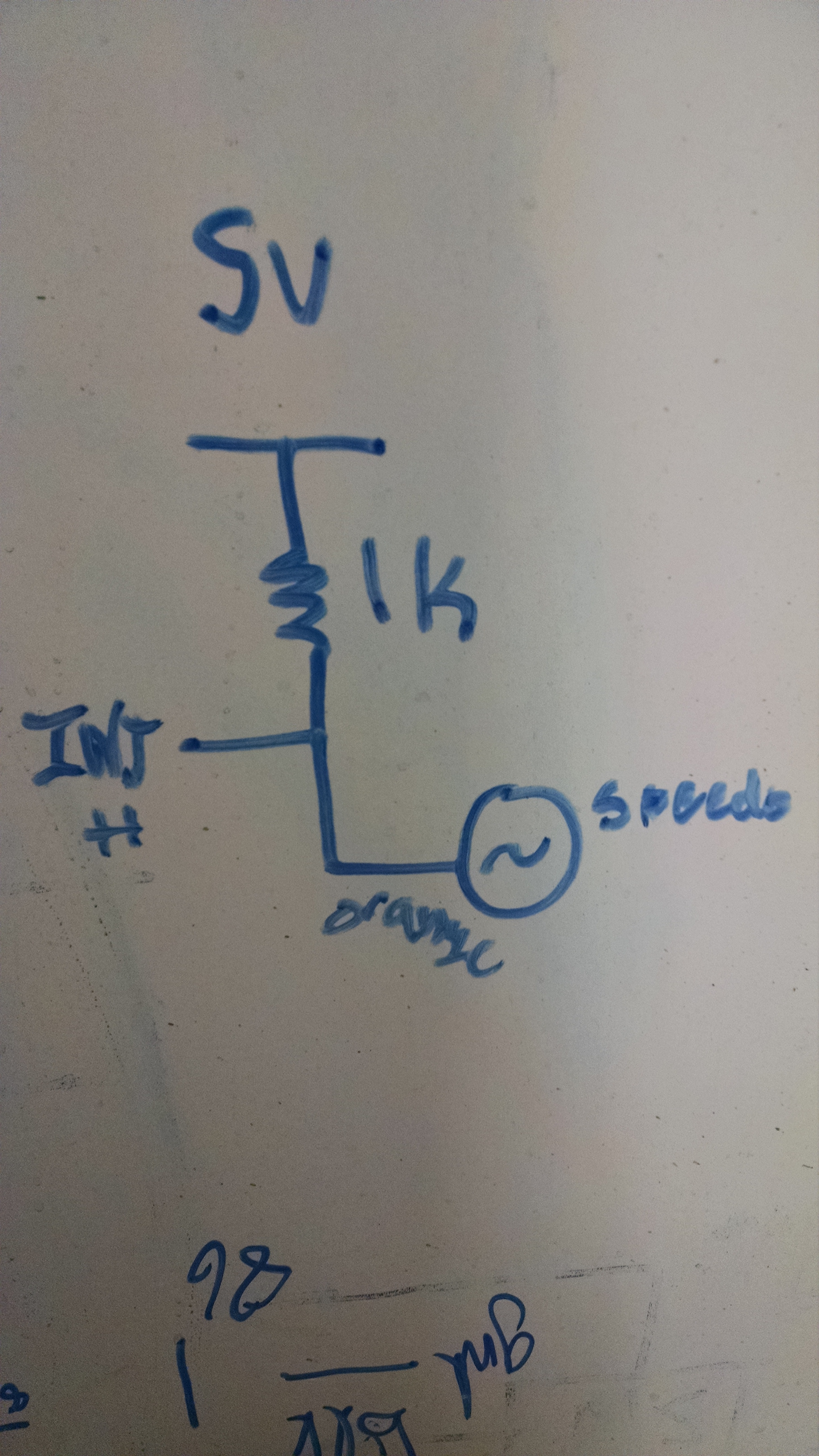
We are now trying to make a 0-5v output signal from the MS3. VSS out provides a switch to ground which means that we should just add a 5v pull up and it should be fine right?
The speedo works when you give it a 0-5v square wave between the two wires that connect to the speedo sensor. So one of these should be tied to ground, and the other pulled up to 5v right?
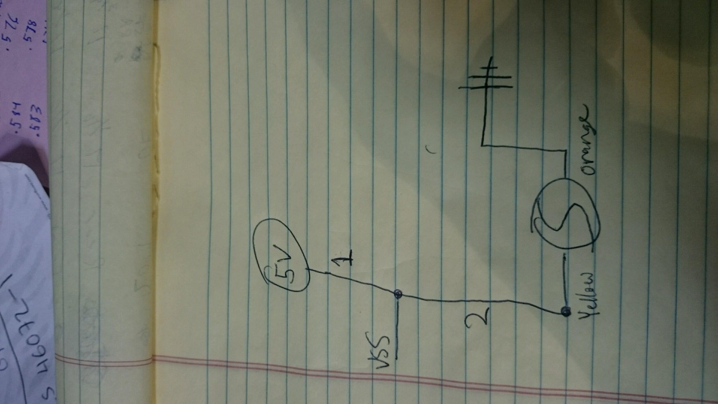
Pull up resistor at location 1.
Is this right? What value resistor for a pullup.
We have the ABS sensor providing a speed signal to the MS3.
We have powered the speedo using a 0-5v square wave.
We are now trying to make a 0-5v output signal from the MS3. VSS out provides a switch to ground which means that we should just add a 5v pull up and it should be fine right?
The speedo works when you give it a 0-5v square wave between the two wires that connect to the speedo sensor. So one of these should be tied to ground, and the other pulled up to 5v right?
Pull up resistor at location 1.
Is this right? What value resistor for a pullup.
Reply
0
0
 11-12-2015, 12:31 AM
#8
Senior Member

Join Date: May 2007
Location: Atlanta
Posts: 997
Total Cats: 156
I'm doing something similar with OBDII PID's - but the good news is that I've already got your MPH figured. Okay, KPH - because OBDII standardizes on metric.
Is the observed pulses per second and the correlating KPH on the gauge. Functionally I fudged together this equation - with some compensations for the microcontroller.
Is the observed pulses per second and the correlating KPH on the gauge. Functionally I fudged together this equation - with some compensations for the microcontroller.
Code:
if (kph > 240) kph = 240; // quick sanity check
    delaytime = (360000 / kph) - 20; //20us compensation for swing time
    next_speedo_toggle = current_time + delaytime;
Reply
0
0
11-12-2015, 07:24 PM
#9

Personally, with how fucked up and shitty miata gauges are, I'd only use that PPM math as a starting point. Then I'd put the wheels in the air in the garage, and fiddle with that output until the gauge matched the math you do to convert RPM and gear ratio. Or use a GPS on the road to fiddle with it.
Reply
0
0
11-12-2015, 07:29 PM
#10
SADFab Destructive Testing Engineer
Thread Starter
iTrader: (5)
Join Date: Apr 2014
Location: Beaverton, USA
Posts: 18,642
Total Cats: 1,866
Thats a cool idea. This solution was meant to be as simple as possible. Should just be 1 wire from the ECU to the speedo. (Maybe 2)
Reply
0
0
11-12-2015, 08:11 PM
#11
Senior Member
Join Date: May 2007
Location: Atlanta
Posts: 997
Total Cats: 156
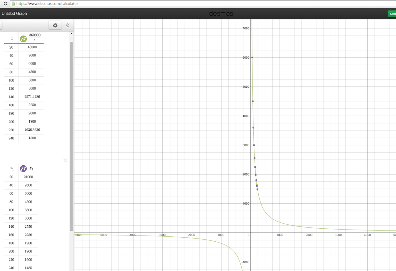
The PPM math came from observation - I tossed pulses at it, tweaked them until I had points (x1 and y1 correlations) then found the equation afterwards. It's not terrible on the speedo side - you can see slight deviations from my calcs, but I think it's accurate enough(tm).
The tach? Now that one is wonky. I ended up having to use a piecemeal function to get it accurate (originally dialed in a accurate to 100rpm lookup table) and it's not a square wave, the tach starts fluctuating wildly if a minimum low(been awhile, can't remember if it's low or high) time isn't maintained.
The tach? Now that one is wonky. I ended up having to use a piecemeal function to get it accurate (originally dialed in a accurate to 100rpm lookup table) and it's not a square wave, the tach starts fluctuating wildly if a minimum low(been awhile, can't remember if it's low or high) time isn't maintained.
Reply
0
0
11-12-2015, 09:35 PM
#12

The PPM math came from observation - I tossed pulses at it, tweaked them until I had points (x1 and y1 correlations) then found the equation afterwards. It's not terrible on the speedo side - you can see slight deviations from my calcs, but I think it's accurate enough(tm).
The tach? Now that one is wonky. I ended up having to use a piecemeal function to get it accurate (originally dialed in a accurate to 100rpm lookup table) and it's not a square wave, the tach starts fluctuating wildly if a minimum low(been awhile, can't remember if it's low or high) time isn't maintained.
The tach? Now that one is wonky. I ended up having to use a piecemeal function to get it accurate (originally dialed in a accurate to 100rpm lookup table) and it's not a square wave, the tach starts fluctuating wildly if a minimum low(been awhile, can't remember if it's low or high) time isn't maintained.
What are the X and Y axes on your graph?
Reply
0
0
11-12-2015, 10:14 PM
#13
Senior Member
Join Date: May 2007
Location: Atlanta
Posts: 997
Total Cats: 156
X is kph, Y is microseconds until next pulse. So.. ugh, this'll be annoying to solve.
1 mile = 8k pulses
so.. 60 seconds at 60mph = 1 mile (make this easy on myself)
60mph = 96.5606 kph
360000 / 96.5606 kph = 3728.22869783 us pulse rate
6000000 microseconds in a minute / 3728.22869783
= 16093.433 signal switchings from high to low and low to high so.. /2 .. so.. 8k?
close enough? (to be fair - I only use integer math in my code for speed. accurate 'nuff.)
Reply
0
0
11-12-2015, 10:26 PM
#14
SADFab Destructive Testing Engineer
Thread Starter
iTrader: (5)
Join Date: Apr 2014
Location: Beaverton, USA
Posts: 18,642
Total Cats: 1,866
X is kph, Y is microseconds until next pulse. So.. ugh, this'll be annoying to solve.
1 mile = 8k pulses
so.. 60 seconds at 60mph = 1 mile (make this easy on myself)
60mph = 96.5606 kph
360000 / 96.5606 kph = 3728.22869783 us pulse rate
6000000 microseconds in a minute / 3728.22869783
= 16093.433 signal switchings from high to low and low to high so.. /2 .. so.. 8k?
close enough? (to be fair - I only use integer math in my code for speed. accurate 'nuff.)
1 mile = 8k pulses
so.. 60 seconds at 60mph = 1 mile (make this easy on myself)
60mph = 96.5606 kph
360000 / 96.5606 kph = 3728.22869783 us pulse rate
6000000 microseconds in a minute / 3728.22869783
= 16093.433 signal switchings from high to low and low to high so.. /2 .. so.. 8k?
close enough? (to be fair - I only use integer math in my code for speed. accurate 'nuff.)
Reply
0
0
11-12-2015, 11:03 PM
#15
Senior Member
Join Date: May 2007
Location: Atlanta
Posts: 997
Total Cats: 156
In my circuit I'm including a trimpot that'll give +-10% to allow for wheel / differential flexibility as well since I'm trying to read everything off the OEM ECU. And if you want to get a custom tachometer gauge face from revlimiter, I should be able to scale that as well.
Reply
0
0
11-13-2015, 01:38 AM
#18
Elite Member
iTrader: (2)
Join Date: May 2008
Location: Portland, Oregon
Posts: 3,468
Total Cats: 365
As long as we end up with something I can use to drive an NB speedo cluster with MS3 logs. Or AIM logs. I can write whatever converter is necessary to feed it as long as I know whatever the necessary format is.
Reply
0
0
11-13-2015, 12:41 PM
#19
In my circuit I'm including a trimpot that'll give +-10% to allow for wheel / differential flexibility as well since I'm trying to read everything off the OEM ECU. And if you want to get a custom tachometer gauge face from revlimiter, I should be able to scale that as well.
The Arduino-based one seems to be closer to what you are trying to accomplish and has some more detail in my thread here.
It can take a mostly-arbitrary signal (from any electronic speed sensor), modify it in software to scale it and change the duty cycle, and then output it back into the odometer unit or directly into the gauge.
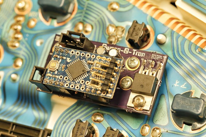
I also designed a much simpler board which allows for scaling the tachometer or speedometer independent of the odometer (not much use if you arent getting in 8k pulses/mile), but some of the general component blocks might be useful.
Reply
0
0