wiring wideband ground to battery terminal
 09-24-2015, 07:57 PM
#1
Senior Member
Thread Starter
iTrader: (3)

Join Date: Oct 2008
Location: Indianapolis
Posts: 610
Total Cats: 12
I am in the midst of doing some rewiring on my 1990 to run a 2002 engine with MS3. My wideband ground was wired to the cylinder head in the past but it always seemed to jump around a little too much. Scott Clark recommended me to wire it to a ground block installed by the battery ground.
Has anyone done this and can you post pictures? What gauge cable and quality should I use to extend the ground to wire it close to the battery?
Thanks
Has anyone done this and can you post pictures? What gauge cable and quality should I use to extend the ground to wire it close to the battery?
Thanks

Reply
 0
0

0
 09-25-2015, 12:12 AM
#3
Boost Pope


iTrader: (8)
Join Date: Sep 2005
Location: Chicago. (The less-murder part.)
Posts: 33,020
Total Cats: 6,588
When the engine is running, the alternator is the primary source of electrical power to the car, and thus, the alternator's chassis is the primary ground for the car. Since the alternator is firmly bolted to the engine, we generally accept the engine block and head to be a surrogate "ideal ground" for electrical loads.
The battery only matters when the engine is not running. After it's started, the battery becomes a load, not a source. Running a ground wire all the way back to the battery is pretty close to the worst possible topology. This means that the current has to travel from the source, all the way back to the battery, then through the ground strap to the body, then all the way through the body to the front, then across the ground strap to the engine, and then finally to the alternator.
I mean, you could do worse, but you'd have to really try. (eg: a self-tapping screw loosely driven into an oversized hole in a piece of rusty sheet metal.)
This is the best idea. For the most stable and accurate readings, the ECU and O2 sensor should share the same ground. This is why all of the OBD-II cars run all of their analog sensor grounds back into the ECU itself, whereas the earlier cars grounded them to whatever point was most convenient. What matters most for an analog sensor is not that it has the best possible ground, but that it see the same ground potential as the ECU.
Reply
0
0
09-25-2015, 12:38 AM
#5

For the most stable and accurate readings, the ECU and O2 sensor should share the same ground. This is why all of the OBD-II cars run all of their analog sensor grounds back into the ECU itself, whereas the earlier cars grounded them to whatever point was most convenient. What matters most for an analog sensor is not that it has the best possible ground, but that it see the same ground potential as the ECU.
A little low on sleep, forgive me if this is a stupid thing to be confused on.
Reply
0
0
09-25-2015, 10:52 AM
#6
Boost Czar

iTrader: (62)
Join Date: May 2005
Location: Chantilly, VA
Posts: 79,493
Total Cats: 4,080
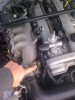
I just want to make sure I'm reading this correctly, for OBD2 cars you're referencing this as the ideal ground, right? The photo seems like it's small on my screen but it should show what I'm asking.
A little low on sleep, forgive me if this is a stupid thing to be confused on.
A little low on sleep, forgive me if this is a stupid thing to be confused on.
the simple fact that i see of a picture of an engine bay means it's wrong.
Reply
0
0
09-28-2015, 04:33 PM
#9
Supporting Vendor

Join Date: Sep 2006
Posts: 2,332
Total Cats: 67
If the ground also runs the heater current through it, this will create more problems than it solves.
Reply
0
0
09-28-2015, 05:16 PM
#10
Elite Member

Join Date: Jul 2005
Posts: 6,420
Total Cats: 84
If there is a single ground wire for both heater and signal (bad juju BTW), then it should be connected to the power ground pin of the ECU, not to the battery - terminal, not the engine block or head, not to Hustler's left nut.
Reply
0
0
09-28-2015, 05:33 PM
#11
Boost Pope
iTrader: (8)
Join Date: Sep 2005
Location: Chicago. (The less-murder part.)
Posts: 33,020
Total Cats: 6,588
The alternative (introducing noise and variable offset into the WBO2 signal by grounding it somewhere other than the ECU) is undesirable.
Reply
0
0

Thread
Thread Starter
Forum
Replies
Last Post
Zaphod
MEGAsquirt
47
10-26-2018 11:00 PM


