VVT box woes.... Please Help
 06-26-2012, 06:41 PM
#1
Junior Member
Thread Starter
iTrader: (2)

Join Date: Jan 2011
Location: Columbus Ohio
Posts: 258
Total Cats: 4
So I recently installed Megasquirt and attempted to get the VVT box running with it.
Car is an 01 running on Rev built MS2
I've got the car running great on MS alone. No problems. It's only when I try to get the VVT box working as well I've got issues.
At first I had a communication issue because I had the wrong type of 2.5mm cable. I corrected that issue now and I'm talking to the box via the VVT Tuner software.
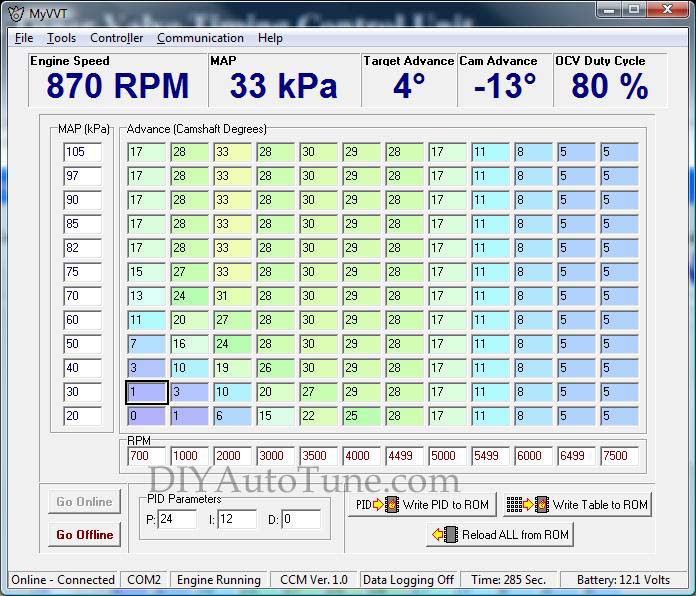
I went online and read the tables on it. I loaded up the base map from diypnp (pid and table values both). I burned that info to the box. I also noticed that under the controller tab in the software there's a setting for "output trigger type". The only one the car will start on is "nb2 inverted".
The car will barely run. It stumbles and sounds terrible.
I attached a log from it on my attempts to start it and it running really bad.
I was wondering if anyone out there had some suggestions?
Possibly some different pid values to use?
No matter what I do it seems to target 20 degrees of advance and actually run at -30 degrees - or that is what it says anyway....
Also I tried to flash the firmware that came with the software download from diy. But I can't seem to get that to work correctly. I noticed there is the option to flash the firmware from inside the software. When you click that it gives you some instructions. Part of the instructions refers to putting a jumper on the ccm. The only jumpers I'm aware of are the ones on the MS that you use if you want to use the box or not. I tried the process with those on the ms and it doesn't work.
Does anyone know if you actually have to put a jumper somewhere on the VVT box itself in order to flash the firmware?
Any help is greatly appreciated.
Car is an 01 running on Rev built MS2
I've got the car running great on MS alone. No problems. It's only when I try to get the VVT box working as well I've got issues.
At first I had a communication issue because I had the wrong type of 2.5mm cable. I corrected that issue now and I'm talking to the box via the VVT Tuner software.
I went online and read the tables on it. I loaded up the base map from diypnp (pid and table values both). I burned that info to the box. I also noticed that under the controller tab in the software there's a setting for "output trigger type". The only one the car will start on is "nb2 inverted".
The car will barely run. It stumbles and sounds terrible.
I attached a log from it on my attempts to start it and it running really bad.
I was wondering if anyone out there had some suggestions?
Possibly some different pid values to use?
No matter what I do it seems to target 20 degrees of advance and actually run at -30 degrees - or that is what it says anyway....
Also I tried to flash the firmware that came with the software download from diy. But I can't seem to get that to work correctly. I noticed there is the option to flash the firmware from inside the software. When you click that it gives you some instructions. Part of the instructions refers to putting a jumper on the ccm. The only jumpers I'm aware of are the ones on the MS that you use if you want to use the box or not. I tried the process with those on the ms and it doesn't work.
Does anyone know if you actually have to put a jumper somewhere on the VVT box itself in order to flash the firmware?
Any help is greatly appreciated.

Reply
 0
0

0

 06-27-2012, 09:51 AM
#7
Junior Member
Thread Starter
iTrader: (2)
Join Date: Jan 2011
Location: Columbus Ohio
Posts: 258
Total Cats: 4
i tried that too -
either way with the vvt box hooked up and no jumpers or with no vvt box and jumpers the car idles but when you rev it, it's sluggish -
takes a sec to respond
the only way it runs normal is w/ just the ms - jumpers on and vvt solenoid plugged in
either way with the vvt box hooked up and no jumpers or with no vvt box and jumpers the car idles but when you rev it, it's sluggish -
takes a sec to respond
the only way it runs normal is w/ just the ms - jumpers on and vvt solenoid plugged in
Reply
0
0
06-27-2012, 10:16 AM
#9
Junior Member
Thread Starter
iTrader: (2)
Join Date: Jan 2011
Location: Columbus Ohio
Posts: 258
Total Cats: 4
i have tested it in just about all possible ways
the answer to the question you ask is -
with vvt box connected and jumpers off and the solenoid disconnected it idles fine, but is sluggish when you rev it
i'm really curious about this firmware flash procedure and doing it correctly -
if i need to put a jumper on the vvt box to do it i need to know where....
Reply
0
0
06-27-2012, 11:08 AM
#10
Elite Member

iTrader: (10)
Join Date: Jun 2006
Location: Athens, Greece
Posts: 5,976
Total Cats: 355
But its not sluggish without the VVT box connected at all? The original basemap that was provided was for use WITH the VVT controller, and strictly speaking, the VVT engine is in fact sluggish down low when the VVT is not controlled.
Anyway, the problem appears to be that the VVTuner is commanding full advance all the time; PM me to troubleshoot this through email.
Anyway, the problem appears to be that the VVTuner is commanding full advance all the time; PM me to troubleshoot this through email.
Reply
0
0
06-28-2012, 12:43 PM
#11
Junior Member
Thread Starter
iTrader: (2)
Join Date: Jan 2011
Location: Columbus Ohio
Posts: 258
Total Cats: 4
ok so i figured out the procedure for flashing new firmware -
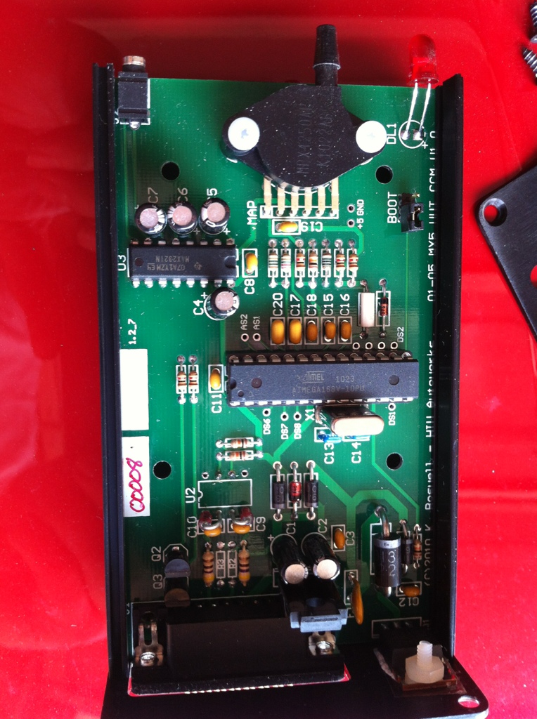
i opened up the vvt box and in this pic in the upper right corner you can see the boot jumper the flash instructions refer to
i flashed the .hex file that came with the download from diy
unfortunately no effect - for some reason the box continues to command full advance at 30 degrees no matter what - even though the table calls for much lower numbers
the only question about the hardware i'm left with now is about the white phillips head plastic screw shown in the lower right corner of this pic as well
i thought it was just a place filler, but now i can see that it's actually connected to something on the board
i've also been in communication with matt at diy about this
hoping for some potential answers
pid settings?
different firmware flash file?
white screw?
does anyone out there in miata turbo land actually use this thing????
Reply
0
0
06-28-2012, 01:10 PM
#12
Elite Member
iTrader: (10)
Join Date: Jun 2006
Location: Athens, Greece
Posts: 5,976
Total Cats: 355
If you see that the commanded advance is 30*, while the cells in the table dictate say 0*, then there is something very wrong with the VVT controller. DIY should be able to help you here. Can you take a vid of this?
I'm running the VVTuner on my car (and several other cars) with no problems so far.
I'm running the VVTuner on my car (and several other cars) with no problems so far.
Reply
0
0
06-29-2012, 11:37 AM
#14
Junior Member
Thread Starter
iTrader: (2)
Join Date: Jan 2011
Location: Columbus Ohio
Posts: 258
Total Cats: 4
Why is U2 not in there?
Plus, I saw on the bill of material
:VVTuner Standalone Programmable VVT Controller Bill Of Materials (BOM)
They says : U2 - Dual Opto Isolator 8DIP - ILCT1
But the only part number I can find from Vishay is MCT-6
MCT6 Fairchild Optoelectronics Group | MCT6-ND | DigiKey
Wonder if someone else have a VVTuner with the U2 in there and can confirm if it is a MCT-6 or ILC-1
Thank you
sharp eye on the parts on the parts on the board
abaloonflies had this first then miatakenji
i'm not sure that the vvt ever actually worked for either of them...
I"m asking Matt at DIY about this..
Reply
0
0
06-29-2012, 11:51 AM
#17
Well, I was talking with Ben at DIY, I would be in just to buy the PCB and Processor, I am trying to figure out the material needed, these are the only pictures I founded, and the only item which was not foundable was the U2...
Even without schematic, a virgin PCB and a Bill of material is enough to build it. IMO
Even without schematic, a virgin PCB and a Bill of material is enough to build it. IMO
Reply
0
0
06-29-2012, 12:58 PM
#19
Supporting Vendor

iTrader: (33)
Join Date: Jul 2006
Location: atlanta-ish
Posts: 12,659
Total Cats: 134
*if* you had the optoisolator, probably. But as we had to bypass it, you'd need a schematic. We felt that this would be too difficult for the average user to assemble, so that's why we do not offer VVTuner in unassembled kit form.

Reply
0
0


