Arduino as ECU?
 10-01-2010, 05:06 PM
#81
Newb

Join Date: Oct 2010
Posts: 6
Total Cats: 0
i'm also thinking about using an Arduino as an ECU, but for converting carb'ed engines to EFI (Toyota Pickup and LandCruiser).
would you be willing to share your arduino code so i can see what you have learned? if i make any headway, i'll be sure and send you everything i learn.
it'd be so cool to have an open source, arduino based EFI/ECU system out there! the possibilities are amazing (pot adjustable air/fuel ratios, digital readouts from all sensors, switchable efficiency/power modes, etc etc).
do you think the arduino is fast enough?
thanks

Reply
 0
0

0
10-01-2010, 05:19 PM
#82
Junior Member

Join Date: Sep 2010
Location: London, England
Posts: 91
Total Cats: 0
i'm also thinking about using an Arduino as an ECU, but for converting carb'ed engines to EFI (Toyota Pickup and LandCruiser).
would you be willing to share your arduino code so i can see what you have learned? if i make any headway, i'll be sure and send you everything i learn.
would you be willing to share your arduino code so i can see what you have learned? if i make any headway, i'll be sure and send you everything i learn.

I will post my source code ASAP.
Really what this project needs is someone with experience interfacing with real Automotive sensors and engine components to build the hardware. I can do the software as that is my day job
it'd be so cool to have an open source, arduino based EFI/ECU system out there! the possibilities are amazing (pot adjustable air/fuel ratios, digital readouts from all sensors, switchable efficiency/power modes, etc etc).
do you think the arduino is fast enough?
thanks
thanks
One thing I haven't got around to yet is worrying about the Emission controls, i.e O2 sensor/purge valves etc... they can come later
The Mazda Miata Performance Handbook (Page 63) explains everything we need to implement them anyway.
Reply
0
0
10-01-2010, 06:45 PM
#83
Newb
Join Date: Oct 2010
Posts: 6
Total Cats: 0
usually the hardware is some voltage value, AFAIK, unless there's an embedded controller that's spitting out actual data. i don't think that would be very common as it doesn't seem necessary in most cases.
i do think the O2 sensor plays an important role in air/fuel mix as it gives you near real-time values. the ECU adjusts the mix depending on how much O2 is left in the exhaust. i assume these values would be read by the arduino as a value between 0 and 1023.
calibration is one thing i'm thinking is going to be tough. for example, if the O2 sensor is giving a value of 250, what does that mean? or perhaps there shouldn't be ANY or as little O2 as possible in the exhaust, so you're striving for a value of 0?
also, how can you figure out the amount of fuel coming out of an injector for a given pulse? you need to know this figure to shoot for your ideal 14.7:1 air/fuel ratio - at least as a starting point. perhaps this is inferred via the O2 sensor?
i'm pretty sure a good prototype will include pots and a good serial debug output that'll allow adjustments on the fly. as sweet spots become apparent in the real world you can firm up the code for your particular engine.
am i anywhere near reality?
Reply
0
0
10-01-2010, 06:56 PM
#84
Junior Member
Join Date: Sep 2010
Location: London, England
Posts: 91
Total Cats: 0
i do think the O2 sensor plays an important role in air/fuel mix as it gives you near real-time values. the ECU adjusts the mix depending on how much O2 is left in the exhaust. i assume these values would be read by the arduino as a value between 0 and 1023.
calibration is one thing i'm thinking is going to be tough. for example, if the O2 sensor is giving a value of 250, what does that mean? or perhaps there shouldn't be ANY or as little O2 as possible in the exhaust, so you're striving for a value of 0?
also, how can you figure out the amount of fuel coming out of an injector for a given pulse? you need to know this figure to shoot for your ideal 14.7:1 air/fuel ratio - at least as a starting point. perhaps this is inferred via the O2 sensor?
i'm pretty sure a good prototype will include pots and a good serial debug output that'll allow adjustments on the fly. as sweet spots become apparent in the real world you can firm up the code for your particular engine.
I have a few issues at the moment with the Arduino's Serial line as it is a little slow... so it can be hard to find a nice slot for transmission...
am i anywhere near reality?

Reply
0
0
10-01-2010, 11:31 PM
#85
Newb
Join Date: Oct 2010
Posts: 6
Total Cats: 0
do you know what kind of resources the serial port takes up? i wonder if it could affect the arduino's ability to crunch away?
i don't think this is an easy project, but i certainly don't think it's impossible. i think you've made some good points about the arduino's capabilities. it's better to forge ahead with a prototype than to fuss about niggly details. the important ones will present themselves.
you're lucky in that you have a car known to work. i still need to fab an intake manifold, a throttle body and a high pressure fuel system! i'll also need to retrofit some crank and/or cam position sensors.
i'm stoked to see your code!
Reply
0
0
10-02-2010, 09:23 AM
#86

i can chime in briefly. Regarding sensors, they're usually analog values. You're looking for 0-5V on an AEM Uego o2 sensor for example, and there's already maps converting volts to AFR for the megasquirt. For the CLT and IAT sensors, there's a program called easytherm which will generate tables based on 3 input resistance-temperature values.
To josdavlar, i suggest you read up on the megasquirt ECU. It's already much more open than other ECUs and you can learn a lot from reading their support pages. One page, linked above i think, lists all the formulas they use.
To josdavlar, i suggest you read up on the megasquirt ECU. It's already much more open than other ECUs and you can learn a lot from reading their support pages. One page, linked above i think, lists all the formulas they use.
Reply
0
0
10-02-2010, 02:12 PM
#87
Junior Member
Join Date: Sep 2010
Location: London, England
Posts: 91
Total Cats: 0
i don't think this is an easy project, but i certainly don't think it's impossible. i think you've made some good points about the arduino's capabilities. it's better to forge ahead with a prototype than to fuss about niggly details. the important ones will present themselves.
For me, this is a project about making an ECU for the lowest possible cost.
I want to get the source code out there, and have someone try it out... I have tested it using a second microcontroller to generate simulated timing signals and it works fine... but a real engine is the test!!
you're lucky in that you have a car known to work. i still need to fab an intake manifold, a throttle body and a high pressure fuel system! i'll also need to retrofit some crank and/or cam position sensors.
i'm stoked to see your code!
Here is the timing diagram:
Last edited by bloodline; 10-02-2010 at 02:43 PM.
Reply
0
0
10-02-2010, 03:22 PM
#88
Junior Member
Join Date: Sep 2010
Location: London, England
Posts: 91
Total Cats: 0
Ok, here is v0.4 of the code. This code has the old short Injector opening schedule. In v0.5 I have rewritten the code to allow for much longer opening times.
As you can also see I have hard coded this to use 10degrees BTDC, as I want to use this as the base to adjust the injector opening time and find out what a real engine needs at 1000. I have started with a default value of 8milliseconds opening time per injector, and would plan to adjust that until I get it right... but I need a real engine to test.
I have tested this on a real Arduino, with a second board simulating an engine providing signals. As a simulation it works fine...
Notice that the spark time is provided by a return value from a function, this is because the timing advance could change every phase. The injector time is global, as I might want to only adjust this less frequently in future.
Code:
// MiataBrain1 ECU V0.4
//
// Copyright (c)2010 Matt Parsons
//
// Mazda MX5 Engine Control Unit Software for the Arduino Microcontroller Board.
//
// Use 8bit variables where ever possible to speed processing.

// defines for setting and clearing register bits
#ifndef cbi
#define cbi(sfr, bit) (_SFR_BYTE(sfr) &= ~_BV(bit))
#endif
#ifndef sbi
#define sbi(sfr, bit) (_SFR_BYTE(sfr) |= _BV(bit))
#endif

// Cycle Time Variables
int MSPT;
unsigned long MSLastFallingEdge;
byte Phase;
byte LastPhase;
unsigned long segTime;

typedef struct{
byte PinCrank;
byte PinCam;
byte PinIgnA;
byte PinIgnB;
byte PinInj1;
byte PinInj2;
byte PinInj3;
byte PinInj4;
} ECUHW;

//Board pin assignment
ECUHW board ={2,3,4,5,6,7,8,9};


//Iginition Variables, you can adjust the firing sequence here
byte IgNActive[]={board.PinIgnB,board.PinIgnA,board.PinIgnB,board.PinIgnA};
unsigned long IgnTime;

//Injector Variables, You can adjust the injector sequence here
byte InJActive[] = {board.PinInj2,board.PinInj3,board.PinInj1,board.PinInj4};
unsigned long InjFlowTime;
unsigned long InjTime;

//Engine Sensor variables
int ThrottlePositionSensor;
int AirFlowSensor;
int AirTemp;
int CoolentTemp;

//Engine Control Variables
//Here we can control the various emission valves etc...
int throttleServo; //on a regular MX5 this woukd be the ISC valve.

void setup(){

// set ADC prescale to 16, 21us per sample, without this the ADC will run too slowly
  sbi(ADCSRA,ADPS2) ;
  cbi(ADCSRA,ADPS1) ;
  cbi(ADCSRA,ADPS0) ;

  Serial.begin(115200);
  Serial.print("\nSystem Boot!\n\nMiataBrain1 ECU v0.4 by Matt Parsons \n");


pinMode(board.PinCam,INPUT);
pinMode(board.PinCrank,INPUT);

pinMode(board.PinIgnA,OUTPUT);
pinMode(board.PinIgnB,OUTPUT);
pinMode(board.PinInj1,OUTPUT);
pinMode(board.PinInj2,OUTPUT);
pinMode(board.PinInj3,OUTPUT);
pinMode(board.PinInj4,OUTPUT);

//The Engine needs to be turing over on the starter by this point.
//Time to Sync with the Engine with the Arduino...
//You might want to switch on the fuel injectors here to fill the manifold with fuel.
//

Phase=1; //default Phase state

//Wait for the Cam
while(digitalRead(board.PinCam==LOW)){}

//Wait for the Crank
while(digitalRead(board.PinCrank==LOW)){}
MSPT=micros(); //Save the current time somewhere...

//Wait for the Crank signal to go low
while(digitalRead(board.PinCrank==HIGH)){}
MSLastFallingEdge=micros();
MSPT=(micros()-MSPT)/100;

//We are now synchronised
}

void loop(){
  //Falling edge of Crank signal
    segTime=micros();

    Phase++;
    if(digitalRead(board.PinCam)==HIGH){Phase=0;}

  //Calculate RPM... Microseconds per 512th of a revolution in our case
    MSPT =(segTime - MSLastFallingEdge) >> 8;
    MSLastFallingEdge = segTime;

  //Calculate Injector Open Time
    //This will close the injector at 156 ticks for low RPM this will be fine, at higher RPM thi will need modification.
    InjTime = segTime + ((156*MSPT)-InjFlowTime);

  //Aguire analog signals
    aquireAnalog();

  //Calculate Fuel amount...
    setInjFlowTime();

  //Send Serial data
    sendData();

  //wait for the right time to turn on injector
    while(micros()<=InjTime){}
   openInjector();

  //Wait for rising edge of Crank signal
    while(digitalRead(board.PinCrank==LOW)){}
////////////////////////////////////////////////////////////////////////
    segTime=micros();

    closeInjector();

  //Calculate Next Time of Ig Based on RPM.
    IgnTime=segTime+(sparkTime()*MSPT);

    //There will be about 800microseconds of time
    //@8000RPM here to do something :)
    //next version will have extra injector time here if needed.

  while(micros()<=IgnTime){}

    fireIgnitor();

 //Wait for Falling Edge of Crank signal... to start the next phase, Yay!
  while(digitalRead(board.PinCrank==HIGH)){}
////////////////////////////////////////////////////////////////////////
}

  void aquireAnalog(){
    //We read them, but don't use them yet
    ThrottlePositionSensor=analogRead(0);
    AirFlowSensor=analogRead(1);
    AirTemp=analogRead(2);
    CoolentTemp=analogRead(3);
  }

  void setInjFlowTime(){
    //Here is where we work out how long the injector need to open
    //this will be based on Throttle, AirFlow, AirTemp, coolent temp etc...
    InjFlowTime=8000; //8 milliseconds, as a default... run a real engine and adjust until you get theexpected idle RPM.
  }

  void sendData(){
  //Just a stub function for now...
  }

  void openInjector(){

    digitalWrite(InJActive[Phase],HIGH);
  }

    void closeInjector(){

    digitalWrite(InJActive[Phase],LOW);
  }

  int sparkTime(){
    return 92; //92 is the number of ticks for 10Deg BTDC
  }

  void fireIgnitor(){
        digitalWrite(IgNActive[Phase],HIGH);
        delayMicroseconds(20);  //Looking at some diagrams suggests the pulse time for this needs to be much longer :)
        digitalWrite(IgNActive[Phase],LOW);
  }
Last edited by bloodline; 10-02-2010 at 06:51 PM. Reason: typos :(
Reply
0
0
10-02-2010, 06:49 PM
#89
I'm Miserable!

Join Date: Jun 2009
Location: albany, ga
Posts: 1,866
Total Cats: 0
How much is the hardware ($50) and what software are you using to tune stuff bloodline?
nvm I see still working on it, I"d be interested in testing later on, are you running the firing of the injectors and spark from a bench setup miata CAS yet?
nvm I see still working on it, I"d be interested in testing later on, are you running the firing of the injectors and spark from a bench setup miata CAS yet?
Last edited by Techsalvager; 10-02-2010 at 07:01 PM.
Reply
0
0
10-02-2010, 07:16 PM
#90
Junior Member
Join Date: Sep 2010
Location: London, England
Posts: 91
Total Cats: 0
Here is a video of my ECU outputs:
The output of my ECU project, the top row of LEDs are the injector signals. The bottom row of LEDs are the spark signals. The CAS timing simulator is running at 160RPM so that it is slow enough to see
Reply
0
0
 10-02-2010, 09:26 PM
#92
I don't know much about the arduino programming language, so here's a couple stupid questions.
Is it hard to create two dimensional arrays? If not, it would be really impressive if you could add the two basic tables (spark advance and VE) for lookup for ignition timing and pulsewidth.
From the megamanual, here's the formula to calculate pulsewidth:
PW = REQ_FUEL * MAP/100 * VE/100 * GammaE/100 + Inj Open Time
VE being the RPMxMAP table, gammae can be ignored, "inj open time" is stored in firmware, and req_fuel is stored in firmware.
Another (probably a stupid one) -- does the arduino have the ability to fire the injectors and the COPs/ignitor?
Tomaj
Reply
0
0
10-04-2010, 05:07 PM
#93
Junior Member
Join Date: Sep 2010
Location: London, England
Posts: 91
Total Cats: 0

Is it hard to create two dimensional arrays? If not, it would be really impressive if you could add the two basic tables (spark advance and VE) for lookup for ignition timing and pulsewidth.
I already have the spark advance sorted out (not included in my example since I really want someone to test it at idle only) using the standard timings found in the original ECU.
From the megamanual, here's the formula to calculate pulsewidth:
PW = REQ_FUEL * MAP/100 * VE/100 * GammaE/100 + Inj Open Time
VE being the RPMxMAP table, gammae can be ignored, "inj open time" is stored in firmware, and req_fuel is stored in firmware.
PW = REQ_FUEL * MAP/100 * VE/100 * GammaE/100 + Inj Open Time
VE being the RPMxMAP table, gammae can be ignored, "inj open time" is stored in firmware, and req_fuel is stored in firmware.
If I am correct, these value can only be known with access to real data, from a working engine.
Another (probably a stupid one) -- does the arduino have the ability to fire the injectors and the COPs/ignitor?
So, yes
Reply
0
0
10-04-2010, 05:23 PM
#94
Junior Member
Join Date: Sep 2010
Location: London, England
Posts: 91
Total Cats: 0
For those interested I built my own CAS, Here is the disk, I cut out the black areas. Mounted two LEDs and two LDRs... one to monitor the inner ring (the Crank Position), the other to monitor the outer ring (The Cam Position).

Reply
0
0
10-04-2010, 06:30 PM
#95
The Arduino just uses C++, so 2D arrays are simple I already have the spark advance sorted out (not included in my example since I really want someone to test it at idle only) using the standard timings found in the original ECU.
I already have the spark advance sorted out (not included in my example since I really want someone to test it at idle only) using the standard timings found in the original ECU.
Not sure how to parse that formula, I assume "required fuel" is given by the throttle position, (MAP/100) is the coefficient of barometric pressure in the manifold as a percentage... The original car doesn't have a sensor for this. (VE/100) would appear to give us our loading value, so we know how much work the engine is doing... I don't know what GammaE is... and "Inj open time" is the time taken for the injector to go from fully closed to fully open...
The MAP value is absolute manifold air pressure, in kPa, so this is using percentage of barometric pressure (i think).
I'm pretty sure your ECU would mostly be used by people with turbos, so the MAP is needed.
The VE value is looked up in the VE table for any given RPM & MAP .
GammaE is basically your "sum of adjustments" (Air temperature, barometric pressure, coolant temp, warmup, whatever).
If I am correct, these value can only be known with access to real data, from a working engine.
If you watch my little video, you can see the injectors (top row of LEDs) firing sequentially, and the ignitors firing in pairs. The sequence is correct, with the TDCs going Cylinder 1, Cylinder 3, Cylinder 4, Cylinder 2
Reply
0
0
10-04-2010, 07:09 PM
#96
Junior Member
Join Date: Sep 2010
Location: London, England
Posts: 91
Total Cats: 0
In theory, the code I posted should "work", and at least hold the engine at an idle... Only once I can confirm that, can I really think about adding all the cool stuff.
REQ_FUEL is a constant calculated based on injector size, engine size, etc. (details on that site from above). It allows you to 'abstract' your fuel table instead of using milliseconds of injector time.
The MAP value is absolute manifold air pressure, in kPa, so this is using percentage of barometric pressure (i think).
I'm pretty sure your ECU would mostly be used by people with turbos, so the MAP is needed.
The VE value is looked up in the VE table for any given RPM & MAP .
GammaE is basically your "sum of adjustments" (Air temperature, barometric pressure, coolant temp, warmup, whatever).
I'm pretty sure your ECU would mostly be used by people with turbos, so the MAP is needed.
The VE value is looked up in the VE table for any given RPM & MAP .
GammaE is basically your "sum of adjustments" (Air temperature, barometric pressure, coolant temp, warmup, whatever).
There's no reason the other arduino you're testing with couldn't supply some values for RPM, MAP, air temp, etc.
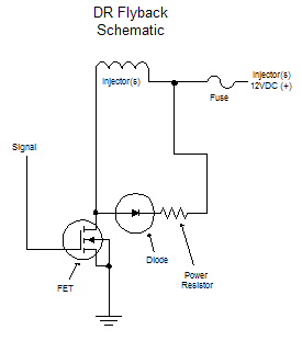
I saw that video, looks good. I was questioning more of the actual juice necessary to operate the injectors and fire the ignition. Not sure what kind of power is required for that.
Like this:
Reply
0
0
 10-05-2010, 12:10 AM
#98
Boost Pope


iTrader: (8)
Join Date: Sep 2005
Location: Chicago. (The less-murder part.)
Posts: 33,019
Total Cats: 6,587
Not sure how to parse that formula, I assume "required fuel" is given by the throttle position, (MAP/100) is the coefficient of barometric pressure in the manifold as a percentage... The original car doesn't have a sensor for this. (VE/100) would appear to give us our loading value, so we know how much work the engine is doing...
Req_Fuel, to be precise, is the theoretical duration of fuel flow required for one injector to achieve perfectly stoichiometric combustion on one cylinder for one cycle, assuming 100% volumetric efficiency at standard temperature and pressure.
In layman's terms, it's the one value you can change to scale everything else from one injector size to another. You could easily eliminate Req_Fuel from the calculation (just assume it to always be 1) and simply tune the VE table appropriately.
TPS doesn't factor into the primary fuel calculation unless you are running in Alpha-N mode. (You're not.)
and "Inj open time" is the time taken for the injector to go from fully closed to fully open...
If I am correct, these value can only be known with access to real data, from a working engine.

In that config, Req_Fuel is 13.4, and let's say that injector lag is 1ms.
So, if we're in a cell where MAP = 100, and VE is 100 kPa, and GammaE is 1, and we assume that each injector squirts only once per engine cycle, then each injector channel will be energized for 14.4 ms for each cycle. (13.4 * 1[MAP] * 1[VE] * 1[GammaE]) + 1
If we're in a cell where VE = 50, then (13.4 * 1 * .5 * 1) + 1 = 7.7 ms
If VE is 50 and MAP = 50, then (13.4 * .5 * .5 * 1) + 1 = 4.35 ms
At least, I think so. It's been a while since I've slept, so if it turns out I'm wrong, then just ignore me.

Reply
0
0
10-05-2010, 04:21 AM
#99
Junior Member
Join Date: Sep 2010
Location: London, England
Posts: 91
Total Cats: 0
I'll just elaborate a bit on ctxspy's rather good answer.
Req_Fuel, to be precise, is the theoretical duration of fuel flow required for one injector to achieve perfectly stoichiometric combustion on one cylinder for one cycle, assuming 100% volumetric efficiency at standard temperature and pressure.
In layman's terms, it's the one value you can change to scale everything else from one injector size to another. You could easily eliminate Req_Fuel from the calculation (just assume it to always be 1) and simply tune the VE table appropriately.
TPS doesn't factor into the primary fuel calculation unless you are running in Alpha-N mode. (You're not.)
... minus the amount of time for the injector to go from fully open to fully closed.
Here's a sample table of VE values, taken from DIY's basemap for a 1.6 engine. The numbers in it are not literally the true volumetric efficiencies of the engine (this is the table in which we apply lots of fudge factors, such as scaling for different desired AFRs) but these are the numbers that work for a Megasquirt following the rules laid out in the formula earlier.
In that config, Req_Fuel is 13.4, and let's say that injector lag is 1ms.
So, if we're in a cell where MAP = 100, and VE is 100 kPa, and GammaE is 1, and we assume that each injector squirts only once per engine cycle, then each injector channel will be energized for 14.4 ms for each cycle. (13.4 * 1[MAP] * 1[VE] * 1[GammaE]) + 1
If we're in a cell where VE = 50, then (13.4 * 1 * .5 * 1) + 1 = 7.7 ms
If VE is 50 and MAP = 50, then (13.4 * .5 * .5 * 1) + 1 = 4.35 ms
At least, I think so. It's been a while since I've slept, so if it turns out I'm wrong, then just ignore me.
Reply
0
0


