mtx-l install help
 01-09-2012, 04:27 AM
#1
Junior Member
Thread Starter

Join Date: Oct 2010
Location: Durban, South Africa
Posts: 75
Total Cats: 0
Busy installing my new mtx-l and ms2 from reverant. Got the ground wire and sensor cable routed from the engine bay and now doing the sensor wiring. I would just like to check with guys who are a whole lot more competent than I am with this 
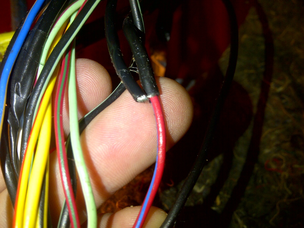
Looking at the harness on my car right by the ECU, the red-blue wire (for the stock o2 sensor) is connected to a thick black wire, not sure why but should I just connect the yellow output of the gauge to the red-blue wire and forget about the black there? The o2 wire is still red-blue in the engine bay.
Also where can I find a source in the car close to the radio for the white wire (dimming function)
Sorry for the stupid questions, I'm useless...

Reply
 0
0

0
01-09-2012, 08:42 AM
#2
Boost Czar


iTrader: (62)
Join Date: May 2005
Location: Chantilly, VA
Posts: 79,493
Total Cats: 4,080
Didnt reverant provide pins for you to wire the MTX-L directly to the db15?
specifically pins 1-4? Where you could have run power, ground and the input right into it?
Behind the radio the Red/Blk is the proper 12v wire for the dimmer.
Looks like that R/L wire on the ECU harness is just shielded.
specifically pins 1-4? Where you could have run power, ground and the input right into it?
Behind the radio the Red/Blk is the proper 12v wire for the dimmer.
Looks like that R/L wire on the ECU harness is just shielded.
Reply
0
0
01-09-2012, 08:59 AM
#3
Junior Member
Thread Starter
Join Date: Oct 2010
Location: Durban, South Africa
Posts: 75
Total Cats: 0
Didnt reverant provide pins for you to wire the MTX-L directly to the db15?
specifically pins 1-4? Where you could have run power, ground and the input right into it?
Behind the radio the Red/Blk is the proper 12v wire for the dimmer.
Looks like that R/L wire on the ECU harness is just shielded.
specifically pins 1-4? Where you could have run power, ground and the input right into it?
Behind the radio the Red/Blk is the proper 12v wire for the dimmer.
Looks like that R/L wire on the ECU harness is just shielded.
Reply
0
0
01-09-2012, 11:13 AM
#6
Elite Member
iTrader: (10)
Join Date: Jun 2006
Location: Athens, Greece
Posts: 5,976
Total Cats: 355
Nope. His MS2 is an MS2V3, not a DIYPNP.
It has been a while, didn't I sent you a 12-pin connector that has a bunch of free wires on it? Does it have a yellow wire on it? If so, that is where you are supposed to connect the wideband output.
It has been a while, didn't I sent you a 12-pin connector that has a bunch of free wires on it? Does it have a yellow wire on it? If so, that is where you are supposed to connect the wideband output.
Reply
0
0
01-09-2012, 03:55 PM
#7
Junior Member
Thread Starter
Join Date: Oct 2010
Location: Durban, South Africa
Posts: 75
Total Cats: 0
The wideband took ages to ship from america (good price though), so it has been awhile. Nope no 12-pin connector, I think the only changes you made on it was the different wiring for the sequential injection (I'm not going to change to that yet). Where must I connect up the wideband output then?
Reply
0
0
01-09-2012, 04:18 PM
#8
Elite Member
iTrader: (10)
Join Date: Jun 2006
Location: Athens, Greece
Posts: 5,976
Total Cats: 355
Open the DB-37 connector. There is a yellow wire on pin 23 of the connector, that goes to 3F on the blue connector board. This is where you need to connect the wideband.
Reply
0
0
01-10-2012, 02:47 AM
#9
Junior Member
Thread Starter
Join Date: Oct 2010
Location: Durban, South Africa
Posts: 75
Total Cats: 0
There is a grey wire running from pin 23 to 3F, would this still be the one to connect to?
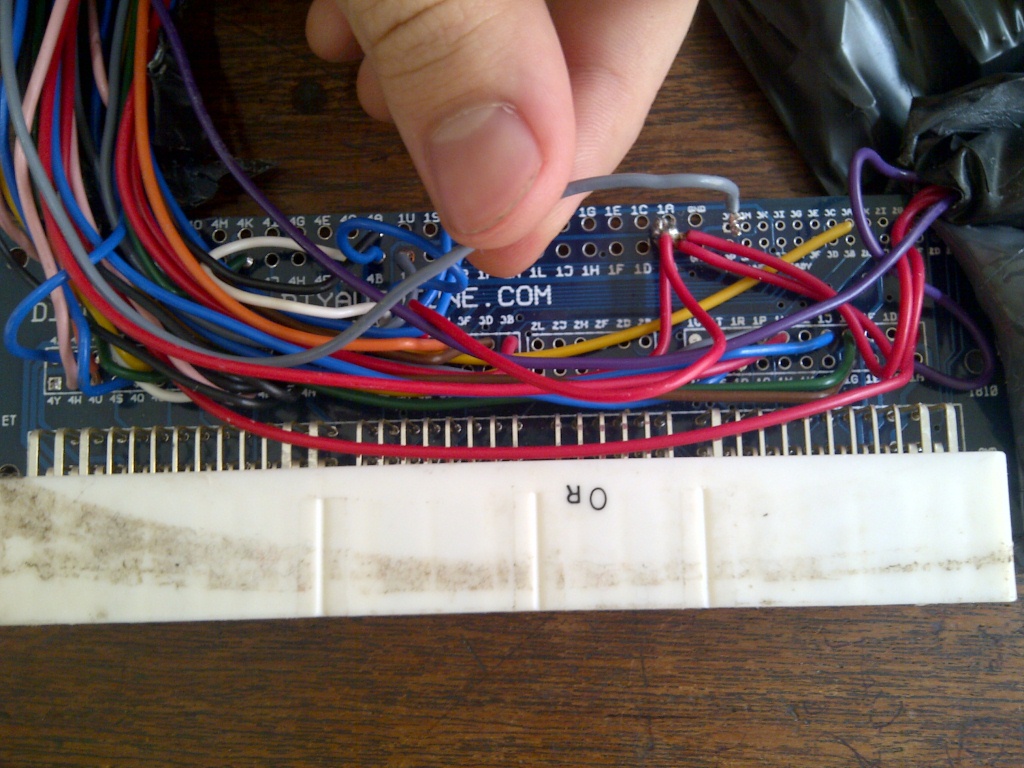
Also the second grey wire used from the DB-37 (pin 27) has come off the blue connector board. which input is that from? seems to be from between 1A to 1V.
Also the second grey wire used from the DB-37 (pin 27) has come off the blue connector board. which input is that from? seems to be from between 1A to 1V.
Reply
0
0
01-10-2012, 08:13 AM
#12
Junior Member
Thread Starter
Join Date: Oct 2010
Location: Durban, South Africa
Posts: 75
Total Cats: 0
Awesome, the wideband is working and the car is fine, its reading about 0.2 higher on Tunerstudio than on the gauge. Got an odd problem though...the aircon won't turn off now!  haha any ideas as to whats going on there?
haha any ideas as to whats going on there?
Reply
0
0
01-10-2012, 02:33 PM
#19
Boost Pope

iTrader: (8)
Join Date: Sep 2005
Location: Chicago. (The less-murder part.)
Posts: 33,020
Total Cats: 6,588
The "thick black wire" is actually a shield, which surrounds the red/blue wire but does not connect to it electrically. Essentially, it's just a braid which completely surrounds the red/blue wire, and then has some black insulation around it. The braid is grounded, and it's simply there to reduce the amount of noise which the red/blue wire picks up from the surrounding wires. Functionally, it's similar to coaxial cable.
Reply
0
0
 And the aircon is all sorted now, Dimitris is a genius!!


