NB Cam Angle Sensor Heatsoak/Failure
 07-10-2015, 04:52 PM
#81
I'm Miserable!

Join Date: Jul 2015
Posts: 60
Total Cats: 0
In the end I ran 68K pullups to 5v...here was what I found (Pullup Ohms/Loss of Signal RPM)
3k3 -2000
10k - 4000ish
33k - 6500
68k - beyond 7500 limiter
Maybe helpful?
Our sync algortihm is pretty nifty with some good rejection windows and compensation for delta RPM, so far worked very well on the rollers...
The ECU core (the ME442, the version we retail is its baby brother, the ME221) we designed was intended for a le mans engine contract we were given so it even models crank mass (if we want to!) the software side is my biz partners Alex domain, mines the hardware however (Which as far as I can tell means he gets to fix bugs in an air conditioned office with a mouse and keyboard and I get to fix them in an MX5 footwell with a soldering iron.. ergh :P )

Reply
 0
0

0
07-11-2015, 01:42 PM
#83
2.2v is high.
Really high.
As in "this is something other than the normal forward voltage across a semiconductor" high.
While you're in an experimenting mood, I'd be hugely curious to know, with a 5v pullup, whether the "on" voltage remains constant regardless of pullup resistance, or if lower "on" voltages are seen with higher pullup resistances.
For the evo unit this was 300 ohms, 210 at 5v.
Reply
0
0
07-12-2015, 11:17 AM
#84
I'm Miserable!
Join Date: Jul 2015
Posts: 60
Total Cats: 0
It wasnt noise we were combating - the signal would literally disappear for 500+ mS - put it down to the FET/tranny in the sensor output circuit overheating. Any idea what the on impedance actually is? We can then work out its P dissipation - maybe a 'safer' option?
Reply
0
0
07-12-2015, 11:28 AM
#85
That's odd, I've never had an issue, and I've run that chip a few different ways. I'm a fan of A2.
You could heat sink the chip, or even tape a thermocouple to it. It's hard to imagine it's overheating, there's a spec'd max current into the pin (with 100 kOhm of resistance, even 12V will only be 0.12 mA, not cooking anything - while it's rated for Vcc + 0.3V, I've run a bunch on +12 and never had an issue, mainly due to the 120 nA thing) anyway, the point is you're allowed +/-40mA on the input pins - perhaps you're asking for too much current on the outputs, somehow? What pull up are you using there (should be a 1k)
I have seen bad grounds/flyback make me lose signal for a while, voltage spikes on the ground plane from turning off a solenoid (VICS, in my case). But something is weird if you're seeing that - tell me more about when it happened?
Reply
0
0
07-12-2015, 11:30 AM
#86
I'm Miserable!
Join Date: Jul 2015
Posts: 60
Total Cats: 0
Abe,
Not on the 9926's front, I mean on the HALL sensor - scoping before the 9926 we saw the actual hall signal dissappear - raising the pullup ohms allowed higher RPM (I assume more 'on' time and hence heat build) before loss of signal - continued high revving at say 10k pullups meant the sensor dropouts would be more frequent, or for longer...
Using a 10k pullup to 3v3 on the output - our MCU is a 3v3 variant, not 5v like MS.
Reply
0
0
07-12-2015, 11:55 AM
#87
Heh, you might like the Evo10 sensor, of course, it's the wrong form factor. But no pull up required, it puts out a 0-3.3v square wave right out of the box.
Have you tried another sensor? They do fail when they get hot, and if it's only partially bad, it'll fail with heat.
I've run my stocker for at least 10's of thousands of miles (street - track is different) with probably a 1k to 12V. Let's think about it - I had 1/12th the voltage drop at 2400 ohm, which means the sensor is effectively 200 ohms. Current is then 12/(2400+200) = 4.6 mA. P = V^2/R = (1V)^2 / 200ohm = 5mW.
That's not a lot of heat, so if you're having troubles with an even bigger resistor (taking the lion's share of the current) I can't imagine it's overheating on what's the equivilent of a dime store laser being pointed at it. Too many cars have lasted too long with much lower pullups.
I'd recommend trying another sensor. Is there a chance you're TOO centered? On my test rig, the signal only looked good when I was off center - not further away, off center. I had the sensor centered on the tooth EDGE, not the middle.
Reply
0
0
11-10-2015, 04:12 PM
#90
I'm not fully convinced they do (I should actually know this, since I've seen it) - but both the evo and the OEM one have a nasty habit of "sticking" at low speed, giving the impression of an inverted signal.
This has a little something to do with alignment. Anyway, I've used it and it's fine, with compatible input circuitry. A word of caution, if you do that, you can't run the OEM ecu without swapping the sensor back again.
So far, I've had no problem with mine.
This has a little something to do with alignment. Anyway, I've used it and it's fine, with compatible input circuitry. A word of caution, if you do that, you can't run the OEM ecu without swapping the sensor back again.
So far, I've had no problem with mine.
Reply
0
0
11-11-2015, 10:29 AM
#91
Junior Member

Join Date: Aug 2005
Location: Cayman Islands
Posts: 440
Total Cats: 17
I was chasing a suspected bad cam sensor and Evo's are like sand on island so it would have been easy to borrow one. Local parts store miraculously had a Miata sensor in stock for a decent price but it end up being the sensor signals were swapped at the Haltech plug (cam was wired as the trigger and crank as home). Swapped the pins to their proper inputs and the car started up on the first crank.
Reply
0
0
11-20-2015, 02:09 PM
#92
SADFab Destructive Testing Engineer

iTrader: (5)
Join Date: Apr 2014
Location: Beaverton, USA
Posts: 18,642
Total Cats: 1,866
Did anything ever come of this? Did swapping to an evo sensor end up working Or did people just start using MS3Pros which used the Maxim chip and didn't suck?
Please be number 2, i have a spare 9926 (4?) sitting around.
Please be number 2, i have a spare 9926 (4?) sitting around.
Reply
0
0
 11-20-2015, 07:20 PM
#94
SADFab Destructive Testing Engineer
iTrader: (5)
Join Date: Apr 2014
Location: Beaverton, USA
Posts: 18,642
Total Cats: 1,866
There are two separate issues at play here correct?
Voltage diff between low and high when hot.
Sticking low or high.
Should the maxim fix #1?
Theoretically evo sensor fixes #2, but it can't catch the teeth on the VVT cam.
Is there actually a solution?
Voltage diff between low and high when hot.
Sticking low or high.
Should the maxim fix #1?
Theoretically evo sensor fixes #2, but it can't catch the teeth on the VVT cam.
Is there actually a solution?
Reply
0
0
11-21-2015, 12:18 PM
#95
You can build the circuit into anything - probably even the stock ecu of you tried hard enough.
I really like my custom cam trigger, and the evo sensor works fine. The other circuit (that I used on my old plug and play boards) works well also. More components, but still cheap and easier to do than with the maxim. If you do that, buy a break out board.
I was thinking of releasing kits, including a sensor and a cam toothed wheel - then all the goofy "Miata specific" code goes away and you use the bread and butter MegaSquirt stuff: 36-1 crank wheel and a poll-level 4 toothed cam trigger. Solid timing, low price, low effort, reliable.
Is there any interest?
Reply
0
0
11-21-2015, 12:30 PM
#96
SADFab Destructive Testing Engineer
iTrader: (5)
Join Date: Apr 2014
Location: Beaverton, USA
Posts: 18,642
Total Cats: 1,866
Prot�g� 36-1 and what cam trigger. I'm interested. Will just be using the same VR board I use for ABS sensors
I thought the evo8 sensor didn't work for VVT because it couldn't catch the second tooth.
I thought the evo8 sensor didn't work for VVT because it couldn't catch the second tooth.
Reply
0
0
11-21-2015, 06:44 PM
#97
Ah! I never posted the cam wheel I made up. Due to the iffy behavior with the second tooth (good catch!) I put on a different style of toothed wheel on my cam.
I pressed off the stock one and pressed on a new one, but totally could have done it at home with a hammer. If you heated it, it'd be even easier.

This is roughly the wheel that I made. Here is what the ECU sees:
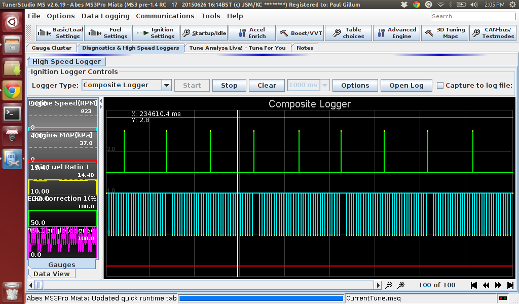
It's 4 evenly spaced teeth, which the ECU can use to keep really tight control on the VVT phasing as it's getting ~2x the updates.
The other advantage is that, by using the "long tooth", the ECU can tell which engine phase it's on without having to wait to have a "speed" and calculate a gap size.
When the engine sees the missing tooth on the crank, the ECU checks the cam. If there's something there, it's the first half of the engine cycle, if not, it's the second. This is unambiguous, and faster, and lets you get into full sequential faster on start up or (god forbid) after a lost sync.
The width of the teeth was chosen to comfortably allow the full range of VVT travel, though of course the set up would work for non-VVT cams just as well.
By buying the Evo sensor, my wheel, a protege wheel and running it through the Maxim or other suitable chip, you have a 0 heartache set up.
That said, it's pretty experimental. It's been working trouble free on my car for the better part of a year - and if I were to do another, I'd probably make a couple small changes. That said, it's a simple system, and a one day job for anyone who's comfortable pulling their own camshaft or crank trigger wheel.
All the benefits of a decent crank trigger and no "sorry, I drive a miata" stuff on the forums. A poll-level cam still uses edge triggering for timing information, so all the MS-I issues go away as well.
Anyway, if there's some interest, I could get some kits together - though frankly if people want to source their own sensors or protege wheels, I don't really care - I was assuming it'd be less of a pain in the butt to get a box full of goodness, and I think I can get a small break on the sensors in quantity.
If there's more interest, I'll post some detailed pics.
https://goo.gl/photos/JU9Faj3m1h6eov8Z6
https://goo.gl/photos/rSbbco3QuaPkyd1HA
Note: The signal is NOT inverted, though you can force it to appear so by putting the sensor too close/too centered on the wheel.
I pressed off the stock one and pressed on a new one, but totally could have done it at home with a hammer. If you heated it, it'd be even easier.
This is roughly the wheel that I made. Here is what the ECU sees:
It's 4 evenly spaced teeth, which the ECU can use to keep really tight control on the VVT phasing as it's getting ~2x the updates.
The other advantage is that, by using the "long tooth", the ECU can tell which engine phase it's on without having to wait to have a "speed" and calculate a gap size.
When the engine sees the missing tooth on the crank, the ECU checks the cam. If there's something there, it's the first half of the engine cycle, if not, it's the second. This is unambiguous, and faster, and lets you get into full sequential faster on start up or (god forbid) after a lost sync.
The width of the teeth was chosen to comfortably allow the full range of VVT travel, though of course the set up would work for non-VVT cams just as well.
By buying the Evo sensor, my wheel, a protege wheel and running it through the Maxim or other suitable chip, you have a 0 heartache set up.
That said, it's pretty experimental. It's been working trouble free on my car for the better part of a year - and if I were to do another, I'd probably make a couple small changes. That said, it's a simple system, and a one day job for anyone who's comfortable pulling their own camshaft or crank trigger wheel.
All the benefits of a decent crank trigger and no "sorry, I drive a miata" stuff on the forums. A poll-level cam still uses edge triggering for timing information, so all the MS-I issues go away as well.
Anyway, if there's some interest, I could get some kits together - though frankly if people want to source their own sensors or protege wheels, I don't really care - I was assuming it'd be less of a pain in the butt to get a box full of goodness, and I think I can get a small break on the sensors in quantity.
If there's more interest, I'll post some detailed pics.
https://goo.gl/photos/JU9Faj3m1h6eov8Z6
https://goo.gl/photos/rSbbco3QuaPkyd1HA
Note: The signal is NOT inverted, though you can force it to appear so by putting the sensor too close/too centered on the wheel.
Reply
0
0
11-21-2015, 10:41 PM
#100
SADFab Destructive Testing Engineer
iTrader: (5)
Join Date: Apr 2014
Location: Beaverton, USA
Posts: 18,642
Total Cats: 1,866
I would be in depending on price. I'm still 1.6 right now but I already have the parts and am planning on switching to a maxim chip this winter
Reply
0
0


