Sequential Fuel Injection and Electromotive
 10-11-2012, 02:41 PM
#1
Senior Member
Thread Starter
iTrader: (2)

Join Date: Jan 2010
Location: Denver
Posts: 904
Total Cats: 14
Looking for some help with sequential fuel injection for a 1.6 engine.
I just picked up an Electromotive Gt and plan to run it on my FP miata.
I need to provided a camshaft angle signal to the ems for sequential fuel injection. I am looking at modifying a cas to do the job. My first question, is there one cas that is preferable to modify? I have not seen the inside of a 94-97 cas. For signal I thought about having a plate machined to provide the rising edge to trigger the signal, and making the appropriate modifications to the housing of the cas to hold the sensor. Does this sound like a viable solution? This stuff is a bit over my head, but will be worth the trouble and headache as it will allow my tuner to trim the injectors and even up cylinder temps.
One of the other reasons I have chosen to go with the electromotive is the ability to use a potentiometer to control mixture on the fly. If the car is running a bit rich or lean of target AFR adjustment is as simple as moving a slider one direction or the other. I lost a qual session at RA due to a miss calculation on fuel, the electromotive once properly configured, will prevent this from happening.
Any ideas, pics, or dyi instructions on modifying a cas to provide the needed signal are greatly appreciated.
Last edited by hingstonwm; 10-11-2012 at 05:56 PM.

Reply
 0
0

0
10-11-2012, 06:43 PM
#2
Boost Pope


iTrader: (8)
Join Date: Sep 2005
Location: Chicago. (The less-murder part.)
Posts: 33,019
Total Cats: 6,587
I'm honestly not sure it's possible anymore to make a distinction (by year) as to which engines are going to have the optical style sensor (with a slotted flat plate) as opposed to the magnetic sensor (with two concentric cups with teeth stamped into them.)
If you can find a magnetic-style sensor, you can easily cut one of the two teeth off of the CMP cup and not have to machine any fancy new parts.
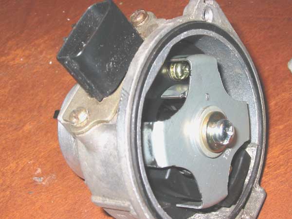
You can see that the larger, outer cup has four evenly-spaced teeth. That's the "Crank" signal.
Barely visible beneath it is another cup with two teeth. That's the "Cam" signal, and if you slice of one of those teeth, you'll have an absolute phase reference.
HOWEVER:
None of this should be necessary.
Regardless of whether they had an optical or a magnetic CAS, the '90-'97 engines all produced exactly the same CAS pattern.
One of the two CMP teeth is longer than the other, such that it's high during an entire rise-fall cycle of CKP, whereas the other CMP tooth is high during a CKP rise, but low during a CKP fall:
This is enough information for most ECUs to figure out the difference and run fully sequential. The stock '94-'97 ECUs worked this way, as do the MS2/3, the Hydra, etc. I don't know anything about Electromotive, but it's worth investigating whether it can run sequential withou havig to modify your CAS. When speaking to the Electromotive crowd, you may find that they refer to our CAS pattern as "4G63", as that was the Mitsubishi engine which it was originally installed on.
If you can find a magnetic-style sensor, you can easily cut one of the two teeth off of the CMP cup and not have to machine any fancy new parts.
You can see that the larger, outer cup has four evenly-spaced teeth. That's the "Crank" signal.
Barely visible beneath it is another cup with two teeth. That's the "Cam" signal, and if you slice of one of those teeth, you'll have an absolute phase reference.
HOWEVER:
None of this should be necessary.
Regardless of whether they had an optical or a magnetic CAS, the '90-'97 engines all produced exactly the same CAS pattern.
One of the two CMP teeth is longer than the other, such that it's high during an entire rise-fall cycle of CKP, whereas the other CMP tooth is high during a CKP rise, but low during a CKP fall:
This is enough information for most ECUs to figure out the difference and run fully sequential. The stock '94-'97 ECUs worked this way, as do the MS2/3, the Hydra, etc. I don't know anything about Electromotive, but it's worth investigating whether it can run sequential withou havig to modify your CAS. When speaking to the Electromotive crowd, you may find that they refer to our CAS pattern as "4G63", as that was the Mitsubishi engine which it was originally installed on.
Reply
1
1
10-11-2012, 09:57 PM
#3
Senior Member

Join Date: Aug 2010
Location: Maumelle, AR
Posts: 613
Total Cats: 3
This might work with the optical cas, I bet electromotive can read a 12 tooth https://www.miataturbo.net/ecus-tuni...upgrade-57770/
Reply
0
0
10-11-2012, 10:02 PM
#4
2 Props,3 Dildos,& 1 Cat
iTrader: (8)
Join Date: Jun 2005
Location: Fake Virginia
Posts: 19,338
Total Cats: 573
Electromotive at least up to the Tec3 needed a single pulse somewhere from 90 to 3 degrees before TDC.
If I remember correctly, I had to modify the NA CAS quite a bit to get that to occur. I used the inner wheel and removed one of the teeth maybe. Then I drilled a hole for the tiny little locating pin on the center shaft rotor thing to reposition it so it would fall in that 90-3 degree range. You only have to get it close because you do get some adjustability on the CAS for timing.
oh hey I found a pitcher:
https://www.miataturbo.net/megasquir...e4/#post785458
The four-tab wheel is keyed to the shaft which is keyed to the cam. The inner/bottom/smaller wheel is keyed via a pin to the top/outer/bigger wheel. Drilled the new hole in the top wheel to relocate the bottom one. Smaller wheel has the second tab removed.
Reply
0
0
10-11-2012, 10:03 PM
#5
2 Props,3 Dildos,& 1 Cat
iTrader: (8)
Join Date: Jun 2005
Location: Fake Virginia
Posts: 19,338
Total Cats: 573
This might work with the optical cas, I bet electromotive can read a 12 tooth https://www.miataturbo.net/ecus-tuni...upgrade-57770/
Reply
0
0
10-12-2012, 12:33 AM
#7
Boost Pope
iTrader: (8)
Join Date: Sep 2005
Location: Chicago. (The less-murder part.)
Posts: 33,019
Total Cats: 6,587
The aluminum tape might work. Honestly, I've never really checked to see how much clearance there is between the sensor and the plate. If it's wide enough for a piece of tape to fit comfortably, then by all means have a go at it.
Reply
0
0
 10-12-2012, 04:26 PM
#13
Senior Member
Thread Starter
iTrader: (2)
Join Date: Jan 2010
Location: Denver
Posts: 904
Total Cats: 14
I will send a pm to Hustler, to see if he is interested in selling. I am running a 60-2 crank wheel, so I only need the cmp signal. I will need to index the cas and see if I can just rotate it and trigger the signal within electromotive's parameters. If not then I will need to index, unless Hustler is willing to sell his.
Reply
0
0
10-12-2012, 06:02 PM
#15
Senior Member
Thread Starter
iTrader: (2)
Join Date: Jan 2010
Location: Denver
Posts: 904
Total Cats: 14
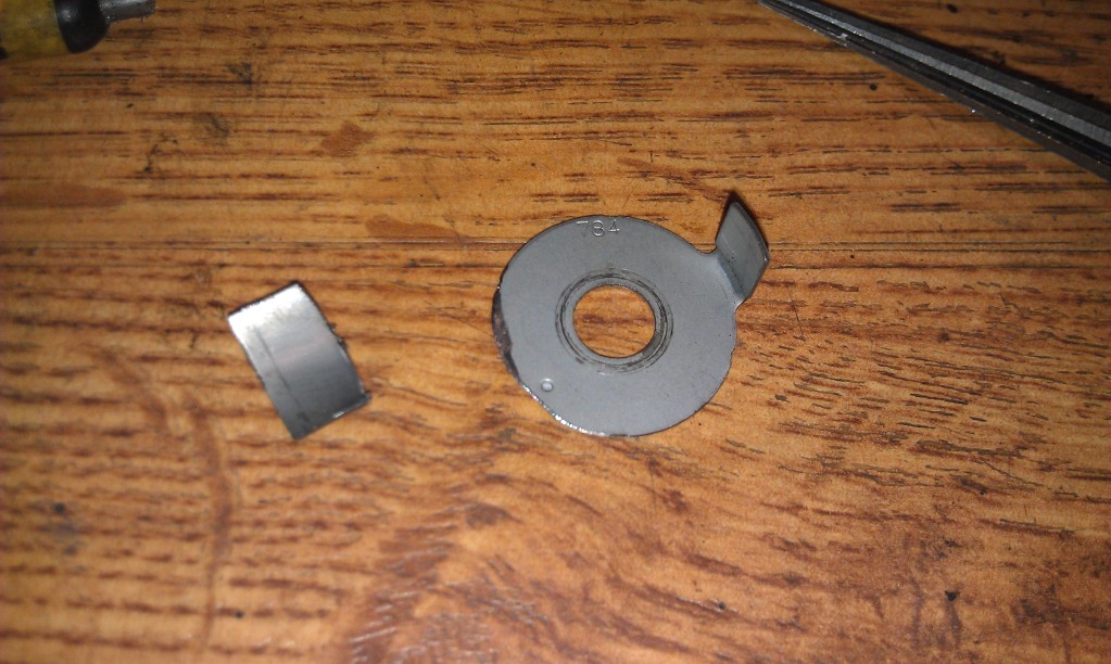
I should have said that I would index, then make the modification to the CMP wheel by removing a tooth, and see if I hat a good signal. If I don't I will index as was previously described.
Reply
0
0
10-18-2012, 05:09 PM
#16
Senior Member
Thread Starter
iTrader: (2)
Join Date: Jan 2010
Location: Denver
Posts: 904
Total Cats: 14
Quick update, I picked up a cas off eBay for 90 bucks. Luck was on my side as it is the magnetic pickup type. I will have to go through my wiring harnesses, but I'm sure I have one that has the cas connector. I am running electromotives 60-2 trigger wheel, so I won't need the cmk signal. The cas that is currently on my engine is gutted, the new one will be modified and take its place, so I can setup sequential fuel injection. I am hoping that sequential fuel injection will also give me a more accurateafr readout on my uego.
Reply
0
0
11-09-2012, 03:31 AM
#17
Senior Member
Thread Starter
iTrader: (2)
Join Date: Jan 2010
Location: Denver
Posts: 904
Total Cats: 14
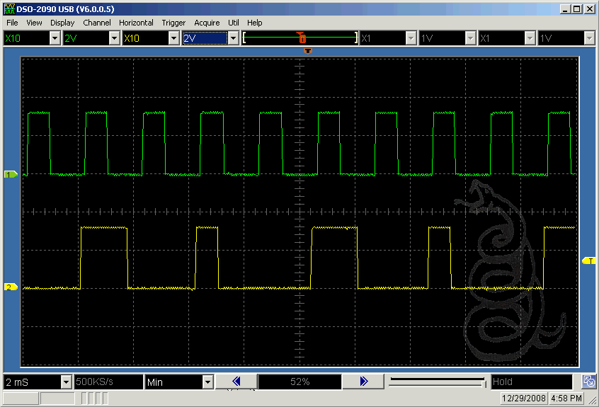
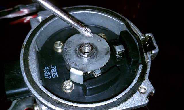
Update. after reading the manual I need a signal between 180 and 6 degrees btdc. It looks like I can acheive this without modifying the timing in the cas. I took a few pics, not sure if the pulse is triggered as the tooth enters the magnetic field or after it passes.
the goal of the pics is to shoe relative position of the tooth on the cas as compared to crank angle. let me know what you think. The crank position wheel was removed so I could see the timing on the cam wheel.
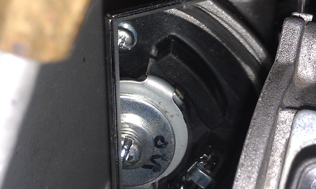
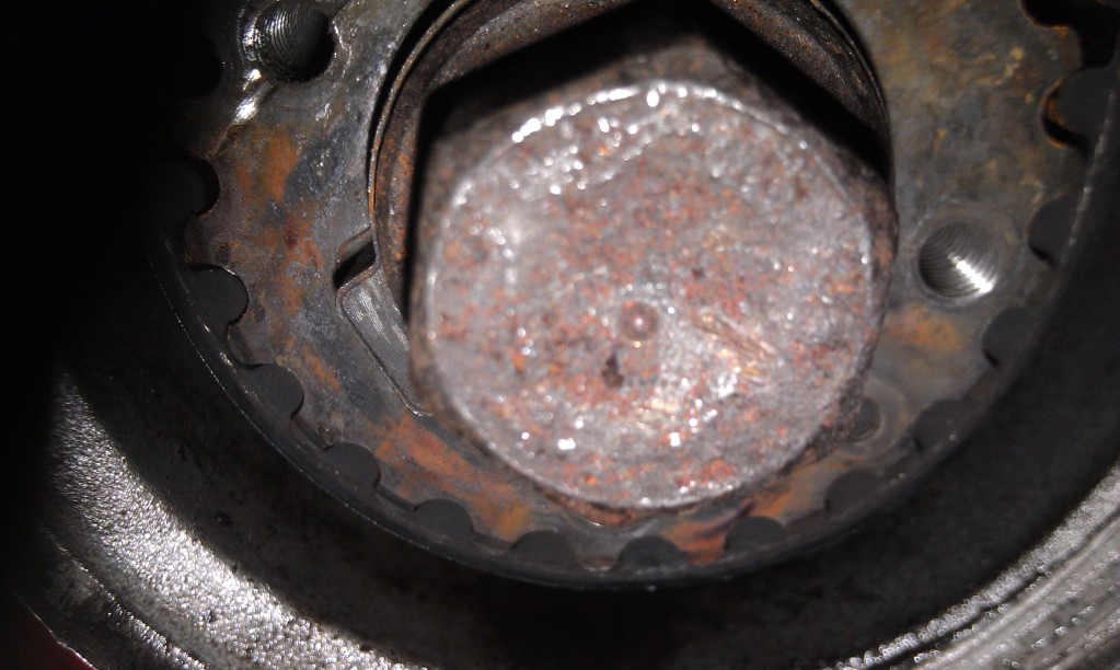
the goal of the pics is to shoe relative position of the tooth on the cas as compared to crank angle. let me know what you think. The crank position wheel was removed so I could see the timing on the cam wheel.
Reply
0
0
11-09-2012, 10:15 AM
#18
2 Props,3 Dildos,& 1 Cat
iTrader: (8)
Join Date: Jun 2005
Location: Fake Virginia
Posts: 19,338
Total Cats: 573
Other than not knowing what pic 3 is, it looks fine. You may have to move the tab around to get it where you want it, but the tolerance zone is very large.
Reply
0
0

Thread
Thread Starter
Forum
Replies
Last Post


