Unknown piggy back identification help?
 05-12-2014, 10:41 AM
#22
Boost Pope


iTrader: (8)
Join Date: Sep 2005
Location: Chicago. (The less-murder part.)
Posts: 33,019
Total Cats: 6,587
Basically, the setup which you have does not conform to any common system which is known to this community. We can't look at it and say "Oh, that's the such-and-such made by this company, here's how it works." Thus, back-tracing the wiring is about the only way you're going to learn anything about it, presupposing that you even care. If it were my car, I'd just park it in the garage and start ordering parts. MS2 or MS3, a wideband O2 sensor, a set of injectors in the 500cc range, etc.
I also just now noticed that there is a tee in the vacuum line between the manifold and the pressure regulator on the fuel rail. I suspect that on the far side of this hose is a secondary rising-rate fuel pressure regulator:
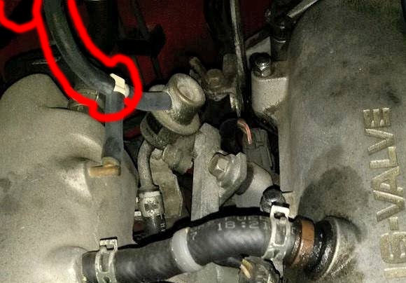
Can we get a picture of that?
I'm also kind of curious as to where the grey wire with the black corrugated sleeve, which comes out of the box into which the AFM connector is plugged, goes.

Reply
 2
2

2
05-12-2014, 10:45 AM
#23
Newb
Thread Starter

Join Date: May 2014
Posts: 26
Total Cats: 1
Could it be 1d and 1b?
The tapped boost ref goes to the magic box and boost gauge.
The extra wire coming out goes to a gm iat in the charge tube.
Considering im a pro tuning shop... I have a ms2 450s and a lc1 here that im going to install in the next few weeks.
Im not all that afraid of it because the previous owner was the furthest thing from a car guy as you could get and he put plenty of hard miles on it with issues.
Last edited by curly; 05-12-2014 at 11:01 AM.
Reply
0
0
 05-12-2014, 11:05 AM
#26
Cpt. Slow
iTrader: (25)
Join Date: Oct 2005
Location: Oregon City, OR
Posts: 14,175
Total Cats: 1,129
Look at this photo:
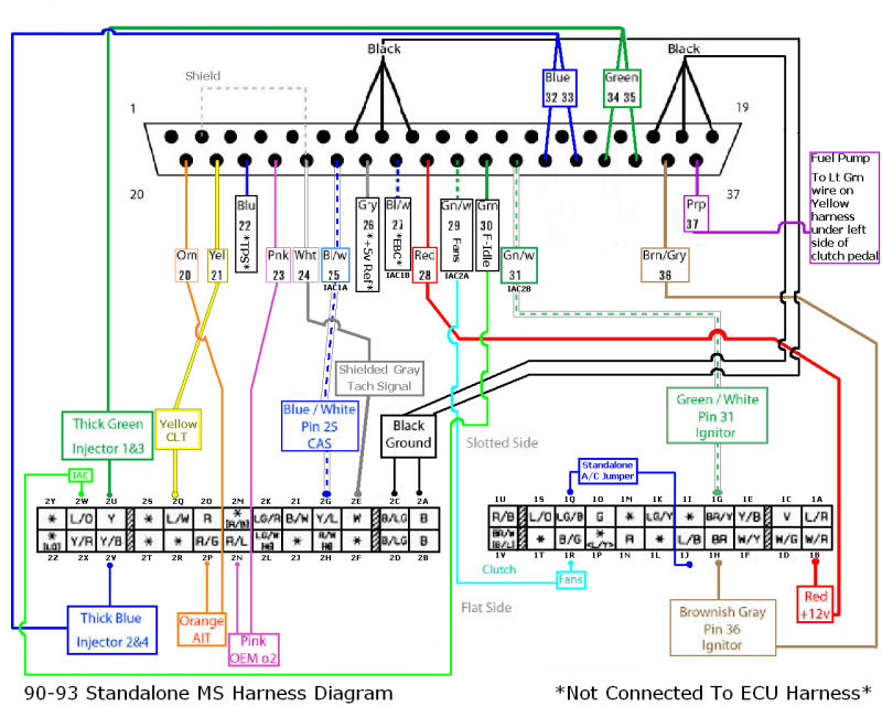
From the picture, the headphone jack appears to be wired into right hand side of the larger connector, as you're looking from the front of it. Which would be 2y and 2z.
Reply
0
0
05-12-2014, 11:12 AM
#27
Boost Pope
iTrader: (8)
Join Date: Sep 2005
Location: Chicago. (The less-murder part.)
Posts: 33,019
Total Cats: 6,587
Yeah, it sure looks to be like it lands near the INJ wires (the two fat yellow ones), which would put it in that vicinity.
2W and 2X are the idle solenoid and purge valve, respectively. 2Z is a tie-line to the transmission computer on vehicles with automatics, and is unused on the M/T cars. 2Y is not indicated as ever having a wire in it on any 1.6 Miata. (I'm assuming that this is not a California-spec '93 car.)
None of that makes any sense.
Last edited by Joe Perez; 05-12-2014 at 11:32 AM.
Reply
0
0
 05-12-2014, 12:27 PM
#32
Newb
Thread Starter
Join Date: May 2014
Posts: 26
Total Cats: 1
I'm beginning to think there is something living inside this ECU.
Reply
0
0
 05-13-2014, 08:09 AM
#37
Boost Czar

iTrader: (62)
Join Date: May 2005
Location: Chantilly, VA
Posts: 79,490
Total Cats: 4,079
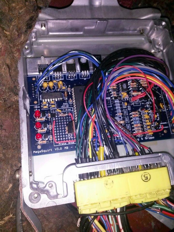
OHHHHHHHHHHHHHHHHHHHHHHHHH I recognize it now.
You bought your miata from someone named Ananth or something like that?
I built that MS for him in 2007 so he could cheat in autocross. The AFM connector box thing is just the map sensor; it used to be hidden in his gutted AFM.
Surprised it wasn't disclosed that it was running MS.
You bought your miata from someone named Ananth or something like that?
I built that MS for him in 2007 so he could cheat in autocross. The AFM connector box thing is just the map sensor; it used to be hidden in his gutted AFM.
Surprised it wasn't disclosed that it was running MS.
Reply
0
0
05-13-2014, 08:43 AM
#40
Boost Pope
iTrader: (8)
Join Date: Sep 2005
Location: Chicago. (The less-murder part.)
Posts: 33,019
Total Cats: 6,587
Look harder. They're there; their input circuit is plainly visible in the circuit board image you posted.
We also now have an answer to the mystery of the 1/8" TRS jack on the dashboard. It's an RS-232 port for programming the ECU. See this pad:
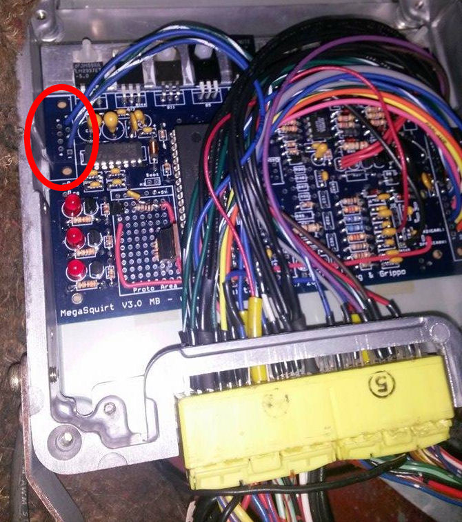
As the owner of a pro tuning shop, you are no doubt aware that in a standard Megasquirt, there would be a DB-9F connector on that pad. In this build, that pad has been wired out externally. You'll need to trace the wiring through to the jack to determine the correct pinout to construct a mating connector- pins 2 (blu/wht) and 3 (grn/wht), in particular, are the Tx and Rx lines, and you need to know which one is tip and which is ring.
Haha- my first thought as well -"Ok, I KNOW I've seen that ECU before!"
We also now have an answer to the mystery of the 1/8" TRS jack on the dashboard. It's an RS-232 port for programming the ECU. See this pad:
As the owner of a pro tuning shop, you are no doubt aware that in a standard Megasquirt, there would be a DB-9F connector on that pad. In this build, that pad has been wired out externally. You'll need to trace the wiring through to the jack to determine the correct pinout to construct a mating connector- pins 2 (blu/wht) and 3 (grn/wht), in particular, are the Tx and Rx lines, and you need to know which one is tip and which is ring.
Haha- my first thought as well -"Ok, I KNOW I've seen that ECU before!"
Reply
0
0


