
DIY: How to tap fuel rail on NB2 for return fuel system
 03-07-2016, 08:45 PM
#1
Junior Member
Thread Starter

Join Date: Nov 2015
Posts: 82
Total Cats: 15
So with my engine swap project, I did not have pump that would now work with the returnless fuel rail.
I also could not take a NA FPR and put it on the fuel rail because the NB fuel rail is different than me NB2.
List of special tools needed:
1/8 NPT tap
21/64 drill bit
Punch
Fuel line disconnect tool(?)
Carb cleaner
Sealant for the fuel rail outlet barb
I won't go into major detail, but I will go over the general process.
You will have to remove the fuel rail, which requires removing the intake manifold.
Each intake runner will have 2 12mm nuts and there are 2 12mm(?) manifold support bolts. Underneath and between the number 3 and 4 runner there is a 10mm bolt holding a pipe for the oil cooler I believe.
After you remove the intake manifold the fuel rail will have to come out. Unplug each injector and there are 3 12mm bolts holding the rail on. Don't loose any of the bushings for the rail.
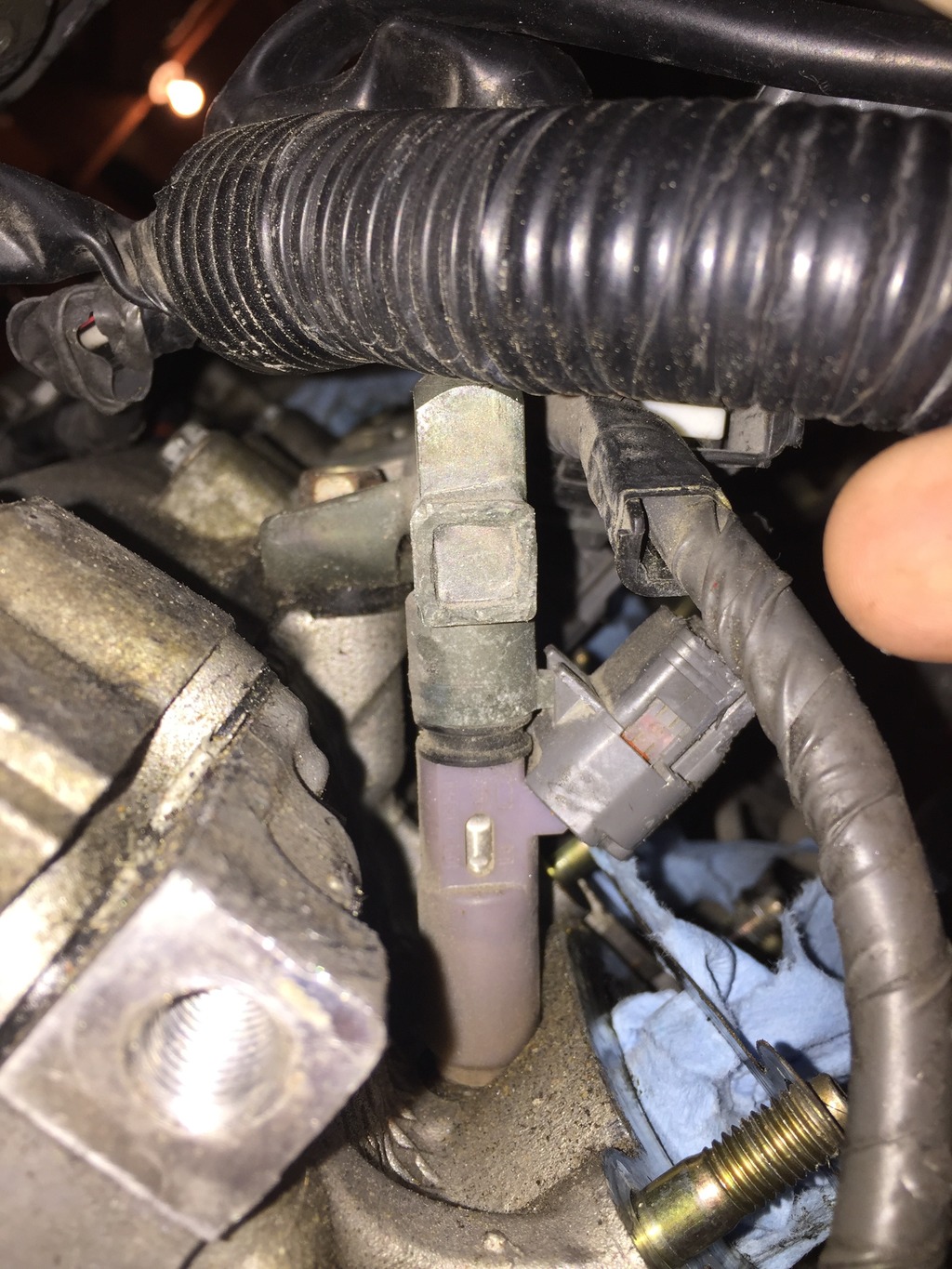
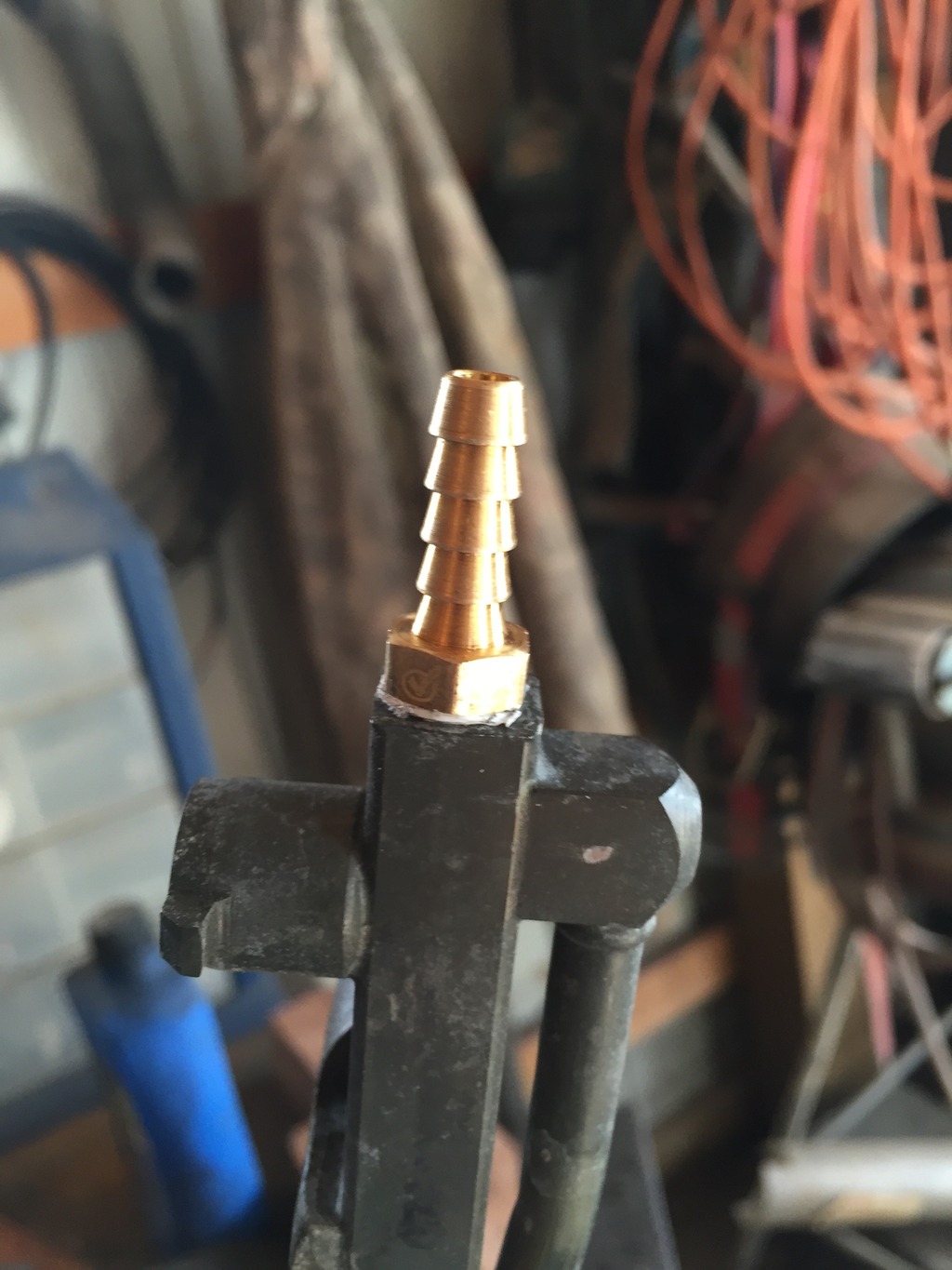
Okay, time for pics. This is where you will tap the hose barb.
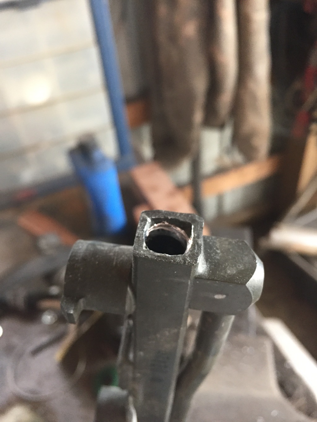
Secure the rail in a vice (don't crush it!)
Use your punch and try to make a pilot dot right in the center. and drill the hole using a 21/64 drill bit.
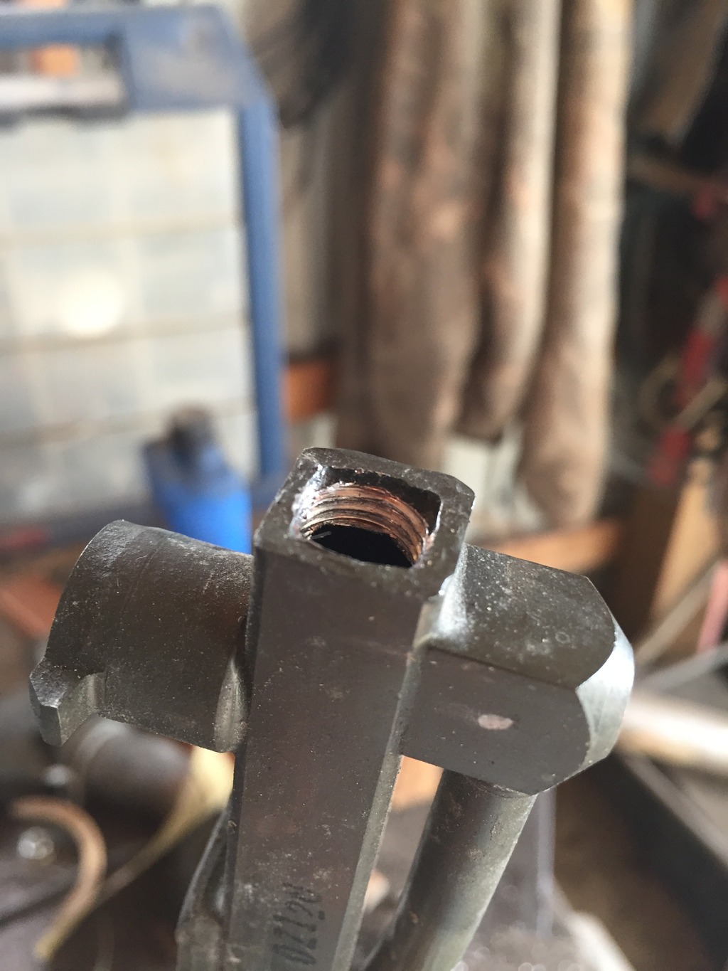
Now take your 1/8" NPT tap and I got about 3 good threads. Grease the end of your tap and it will collect the shavings.
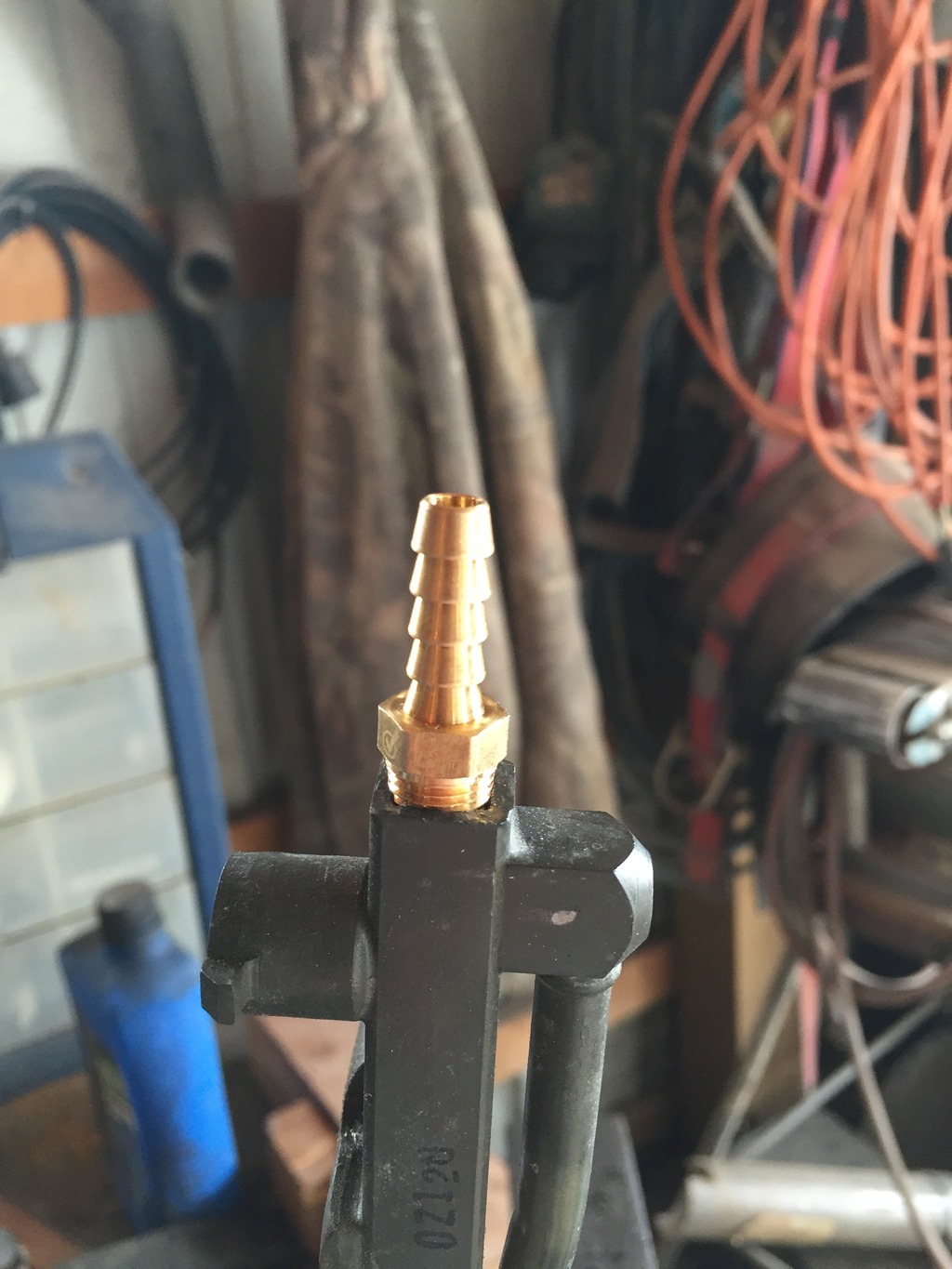
Thread your hose barb in to make sure it's the right one.
At this point grab your carb cleaner and really, really clean the rail out. Get every last shaving out of that thing you do not want them clogging your injectors.
Once you clean it I wrapped my barb twice with teflon and tightened until it bottomed out. You can use whatever sealant you prefer.
Put the rail back on.
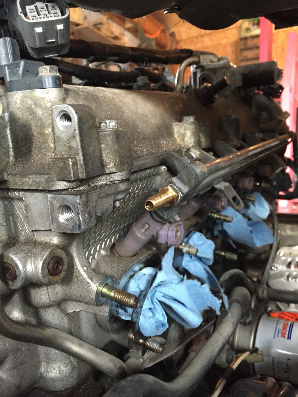
Now you have a return style fuel system!
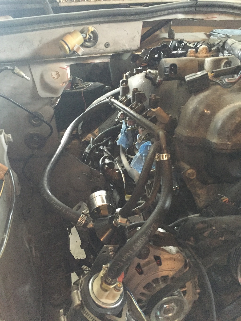
Put your pump before the rail and the regulator after and you're golden!
If I got anything wrong feel free to let me know and I'll fix it.
I also could not take a NA FPR and put it on the fuel rail because the NB fuel rail is different than me NB2.
List of special tools needed:
1/8 NPT tap
21/64 drill bit
Punch
Fuel line disconnect tool(?)
Carb cleaner
Sealant for the fuel rail outlet barb
I won't go into major detail, but I will go over the general process.
You will have to remove the fuel rail, which requires removing the intake manifold.
Each intake runner will have 2 12mm nuts and there are 2 12mm(?) manifold support bolts. Underneath and between the number 3 and 4 runner there is a 10mm bolt holding a pipe for the oil cooler I believe.
After you remove the intake manifold the fuel rail will have to come out. Unplug each injector and there are 3 12mm bolts holding the rail on. Don't loose any of the bushings for the rail.
Okay, time for pics. This is where you will tap the hose barb.

Secure the rail in a vice (don't crush it!)
Use your punch and try to make a pilot dot right in the center. and drill the hole using a 21/64 drill bit.

Now take your 1/8" NPT tap and I got about 3 good threads. Grease the end of your tap and it will collect the shavings.

Thread your hose barb in to make sure it's the right one.

At this point grab your carb cleaner and really, really clean the rail out. Get every last shaving out of that thing you do not want them clogging your injectors.
Once you clean it I wrapped my barb twice with teflon and tightened until it bottomed out. You can use whatever sealant you prefer.

Put the rail back on.

Now you have a return style fuel system!

Put your pump before the rail and the regulator after and you're golden!
If I got anything wrong feel free to let me know and I'll fix it.
Last edited by ajay842; 03-10-2016 at 09:41 AM.

Reply
 2
2

2

 03-10-2016, 08:34 PM
#7
Newb


Join Date: Aug 2015
Location: Oregon
Posts: 18
Total Cats: 0
I used a different approach. It required deleting the VTCS, which I wanted gone anyway.
99 fuel rail off eBay, Turbosmart TS-0402-1002 Fuel Rail Adapter for Toyota/Subaru (trust me this is the right one), Russel -6 AN to rail adapter fitting PN:644110, Earl's PN:165056ERL to convert the supply hard line to -6 AN. NPT to -AN elbow. Various -AN hose ends. Ran the high pressure supply side in -6AN braided hose. Return side (downstream of the regulator) is clamped injector hose. This approach did require some clearance grinding on the intake manifold, but not a lot. I have photos of the clearance grinds as well.
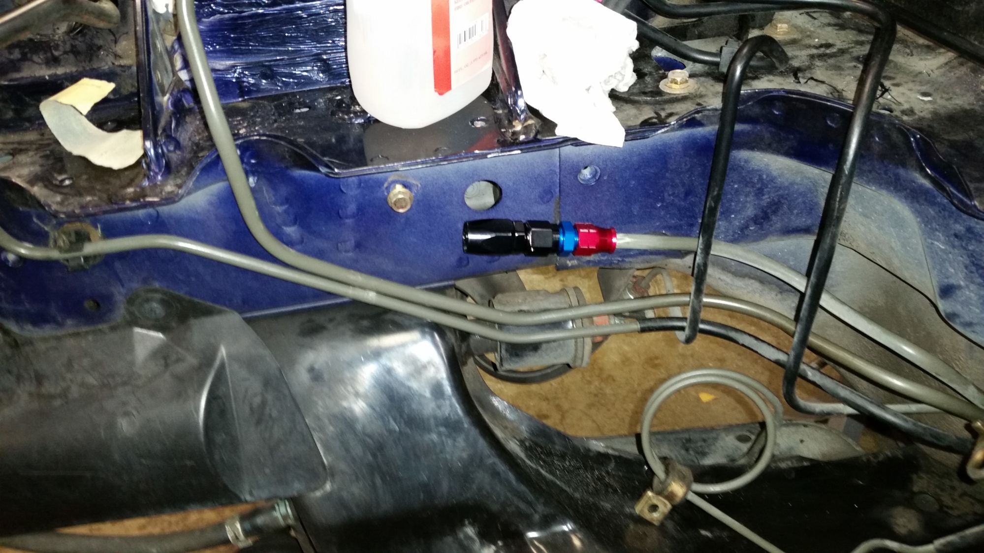
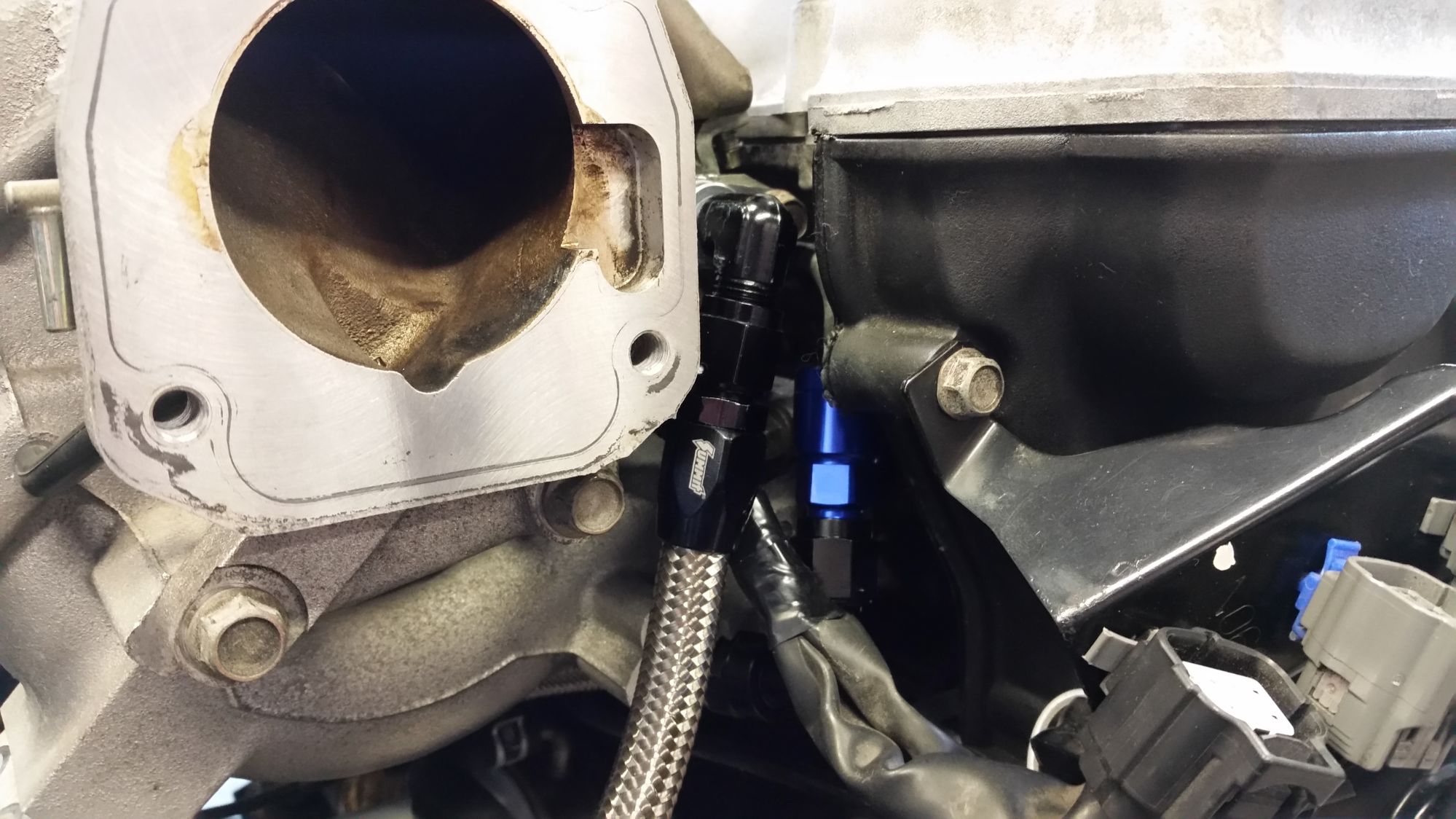
99 fuel rail off eBay, Turbosmart TS-0402-1002 Fuel Rail Adapter for Toyota/Subaru (trust me this is the right one), Russel -6 AN to rail adapter fitting PN:644110, Earl's PN:165056ERL to convert the supply hard line to -6 AN. NPT to -AN elbow. Various -AN hose ends. Ran the high pressure supply side in -6AN braided hose. Return side (downstream of the regulator) is clamped injector hose. This approach did require some clearance grinding on the intake manifold, but not a lot. I have photos of the clearance grinds as well.
Reply
0
0
03-12-2016, 12:12 PM
#8
Junior Member

Join Date: Oct 2014
Location: North Carolina
Posts: 53
Total Cats: -1
I know its a little bit more off topic, but does anybody know If a set of NC (2006-15) miata injectors have the same head/nozzle size as the ports for our injectors?
I am thinking about buying a set of grams/skunk2 injectors from a guy. I know the tophats are different, and I can get those, but I dont know if the injector body/nozzle/head will seat into our port
I have a 2005 MSM. And the injector kit he bought was for an NC...but being that they are EV14 injectors i think that the injector body would be the same and the wires and top hats are just different
Sorry I didnt want to make a new thread just for a "yes/no" question, and i cant find anyone chatting about it.
And i saw brain posted here. I feel like he may know
Reply
0
0
03-12-2016, 01:27 PM
#10
Cpt. Slow
iTrader: (25)
Join Date: Oct 2005
Location: Oregon City, OR
Posts: 14,179
Total Cats: 1,129
OP or Wino?
The much easier method of this is described in the VVT swap thread, just buy a 99 rail and bolt on a 90-97 fpr. Without an in-line FPR, the OP's method would result in an unregulated fuel pressure. But if you are using an aftermarket FPR, it's a nice use of the dozen or so NB2 fuel rails I have...
The much easier method of this is described in the VVT swap thread, just buy a 99 rail and bolt on a 90-97 fpr. Without an in-line FPR, the OP's method would result in an unregulated fuel pressure. But if you are using an aftermarket FPR, it's a nice use of the dozen or so NB2 fuel rails I have...
Reply
0
0
03-12-2016, 07:52 PM
#12
Junior Member
Thread Starter
Join Date: Nov 2015
Posts: 82
Total Cats: 15
OP or Wino?
The much easier method of this is described in the VVT swap thread, just buy a 99 rail and bolt on a 90-97 fpr. Without an in-line FPR, the OP's method would result in an unregulated fuel pressure. But if you are using an aftermarket FPR, it's a nice use of the dozen or so NB2 fuel rails I have...
The much easier method of this is described in the VVT swap thread, just buy a 99 rail and bolt on a 90-97 fpr. Without an in-line FPR, the OP's method would result in an unregulated fuel pressure. But if you are using an aftermarket FPR, it's a nice use of the dozen or so NB2 fuel rails I have...
Reply
0
0
03-12-2016, 09:18 PM
#14
Newb
Join Date: Aug 2015
Location: Oregon
Posts: 18
Total Cats: 0
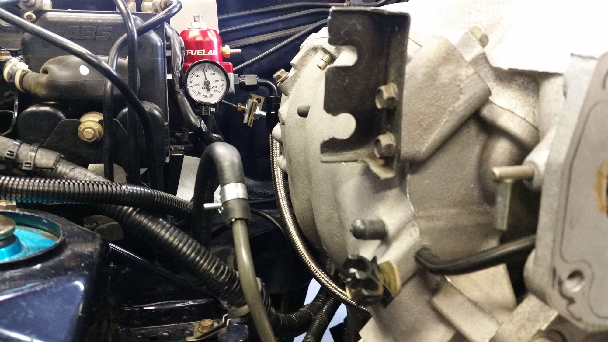
It's rated to 250 psi on aluminum tubing. Now, my hard line isn't aluminum, but it's soft. I don't actually know the hard line material, probably a copper/steel alloy. I actually found this fitting conversion on several user threads in the forum and decided to go with it. Sometimes our needs force us to use less than ideal solutions. The high pressure side of the system, excluding the fuel rail was pressure tested at 125% of operating pressure for four hours with no pressure loss, so I'm reasonably confident in it. Heck, I'm still running hose on barb at the back end, but I plan to upgrade it later.
I went through the VVT swap thread pretty thoroughly before I made my final plan. I went with the adjustable FPR for more future flexibility.
I went through the VVT swap thread pretty thoroughly before I made my final plan. I went with the adjustable FPR for more future flexibility.
Reply
0
0
03-12-2016, 10:42 PM
#15

It's rated to 250 psi on aluminum tubing. Now, my hard line isn't aluminum, but it's soft. I don't actually know the hard line material, probably a copper/steel alloy. I actually found this fitting conversion on several user threads in the forum and decided to go with it. Sometimes our needs force us to use less than ideal solutions. The high pressure side of the system, excluding the fuel rail was pressure tested at 125% of operating pressure for four hours with no pressure loss, so I'm reasonably confident in it. Heck, I'm still running hose on barb at the back end, but I plan to upgrade it later.
I went through the VVT swap thread pretty thoroughly before I made my final plan. I went with the adjustable FPR for more future flexibility.
I went through the VVT swap thread pretty thoroughly before I made my final plan. I went with the adjustable FPR for more future flexibility.
I guess the best thing would be testing the system at pressure like you did.
Reply
0
0
03-13-2016, 12:25 AM
#16
Newb
Join Date: Aug 2015
Location: Oregon
Posts: 18
Total Cats: 0
My chief concern with the entire system is that there's no good way to pre-test it under dynamic load. I'm happy with the pressure test and all, but how will it hold up when things start moving around and vibrating? Mines a prepared class autocross car, so it's going to see <100 miles/year. It's going to see tons of stress during those miles. Only time will tell. I've spent a lot of time fretting over my fuel lines. Are they going to rub? Is there too much strain in this bend? Did I leave enough room for this and that to flex under load? On and on. Being on fire is not on my top 10 list of things I want to do.
Reply
0
0
03-13-2016, 04:48 PM
#17

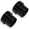
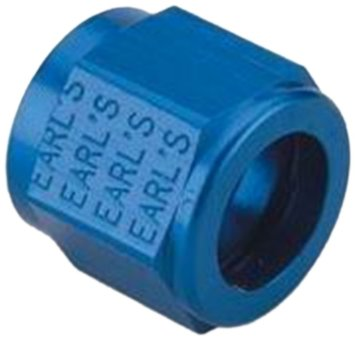
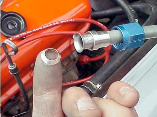
I have the same Earl's compression fittings on my lines a la Soviet and Hustler method. I'm torn as Soviet hasn't seemed to have had any issues with his Earl's fittings and IIRC he runs lots of base pressure on ID1000s with ALLOFIT boost reference.
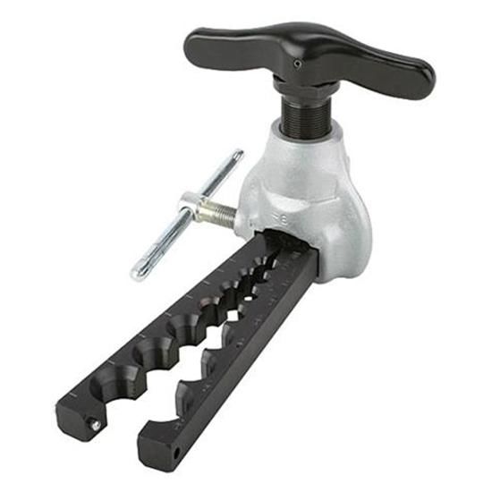
I've been thinking of doing the inverted 37� flare / spacer and B-nut option and AN5 -> AN6 union. Honda guys seem to do this a lot on their steel fuel lines.
+
+
+
I've been thinking of doing the inverted 37� flare / spacer and B-nut option and AN5 -> AN6 union. Honda guys seem to do this a lot on their steel fuel lines.
+
+
+
Reply
0
0
03-13-2016, 04:56 PM
#18
SADFab Destructive Testing Engineer

iTrader: (5)
Join Date: Apr 2014
Location: Beaverton, USA
Posts: 18,642
Total Cats: 1,866
I have the same Earl's compression fittings on my lines a la Soviet and Hustler method. I'm torn as Soviet hasn't seemed to have had any issues with his Earl's fittings and IIRC he runs lots of base pressure on ID1000s with ALLOFIT boost reference.
I've been thinking of doing the inverted 37� flare / spacer and B-nut option and AN5 -> AN6 union. Honda guys seem to do this a lot on their steel fuel lines.
+
+
+
I've been thinking of doing the inverted 37� flare / spacer and B-nut option and AN5 -> AN6 union. Honda guys seem to do this a lot on their steel fuel lines.
+
+
+
Reply
0
0
03-17-2016, 05:03 PM
#19
Senior Member
iTrader: (3)

Join Date: Dec 2007
Location: Seven Valleys, PA
Posts: 638
Total Cats: 11
[QUOTE=Wino;1314893]I used a different approach. It required deleting the VTCS, which I wanted gone anyway.
99 fuel rail off eBay, Turbosmart TS-0402-1002 Fuel Rail Adapter for Toyota/Subaru (trust me this is the right one), Russel -6 AN to rail adapter fitting PN:644110, Earl's PN:165056ERL to convert the supply hard line to -6 AN. NPT to -AN elbow. Various -AN hose ends. Ran the high pressure supply side in -6AN braided hose. Return side (downstream of the regulator) is clamped injector hose. This approach did require some clearance grinding on the intake manifold, but not a lot. I have photos of the clearance grinds as well.
QUOTE]
Thank you!
This is exactly what I have been looking for to complete my fuel system!!!
Reply
0
0

Thread
Thread Starter
Forum
Replies
Last Post
irodd
Miata parts for sale/trade
1
05-07-2016 09:50 PM


