
3d printed intake for N/A NA miatas

 01-10-2016, 11:09 AM
#302
Senior Member

Thread Starter
iTrader: (1)

Join Date: Jul 2012
Location: durham NC
Posts: 792
Total Cats: 143
This is the problem with sharing a design and not having control over the quality of the printing. Also, it turns out that most consumer grade 3d printers suck at large hollow structures made from ABS.
Ideally you want to find someone with a good quality printer and a heated build chamber setup.
I can send you the info for the guy I use to print my plugs, but he doesn't do assembly or acetone vapor bath. I do that part myself. Acetone vapor baths are not super difficult but you will need to buy a few things to do it. There is some info online, just don't do it inside and don't use an open flame for your heat source. Also, if you are unsure, have a plan to deal with a solvent fire.

Reply
 0
0

0
 01-16-2016, 01:48 PM
#305
Senior Member
Thread Starter
iTrader: (1)
Join Date: Jul 2012
Location: durham NC
Posts: 792
Total Cats: 143
FWIW the rc-9310 is used for the 3d printed kits but not the carbon version (the OD of the part is much smaller with the carbon and uses 2.5" filters and elbows).
No idea what will or won't clear the AC since I don't have it on my car. I think the rc 9310 is a pretty tight squeeze.
I abandoned the heatshield. I made a crude one and tested it, there was not a measurable difference in IAT.
No idea what will or won't clear the AC since I don't have it on my car. I think the rc 9310 is a pretty tight squeeze.
I abandoned the heatshield. I made a crude one and tested it, there was not a measurable difference in IAT.
Reply
0
0
01-16-2016, 02:23 PM
#306
FWIW the rc-9310 is used for the 3d printed kits but not the carbon version (the OD of the part is much smaller with the carbon and uses 2.5" filters and elbows).
No idea what will or won't clear the AC since I don't have it on my car. I think the rc 9310 is a pretty tight squeeze.
I abandoned the heatshield. I made a crude one and tested it, there was not a measurable difference in IAT.
No idea what will or won't clear the AC since I don't have it on my car. I think the rc 9310 is a pretty tight squeeze.
I abandoned the heatshield. I made a crude one and tested it, there was not a measurable difference in IAT.
I'll post a picture and silicone part numbers when im done.
Reply
0
0
01-25-2016, 10:08 AM
#308
Senior Member
Thread Starter
iTrader: (1)
Join Date: Jul 2012
Location: durham NC
Posts: 792
Total Cats: 143
The design I have been working with was built around the original 3mm plastic wall thickness. Moving to 1mm carbon walls there is a lot of clearance, which is good, but the design is less optimal than it could be. Also, my labor on these is out of control. The process currently looks like this:
Lay up two halves under vacuum (this is the easy part)
->Oven cure for 12 hours
Trim flanges by hand
Place halves back into mold and tack corners with epoxy
->Oven cure for 6-8 hours
Fill gap with hysol 1c
-> Oven cure for 6 hours
Sand joint smooth to about 200 grit
Laminate strips of carbon over joint and vac bag
-> Oven cure for 12 hours
Hand sand and polish final part
There is a ton of hand trimming and sanding and parts have to wait on 4 epoxy cure cycles.
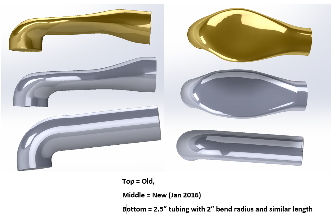
On the new redesign I have used up the available space better- The flat section is thicker and less wide. I also modeled it with surfaces so it can go into cad software easily. The plan is to move the process over to some machined aluminum or fiberglass molds and then bladder mold biaxial sleeves in one shot. No joining, minimal trimming, one epoxy cure cycle.
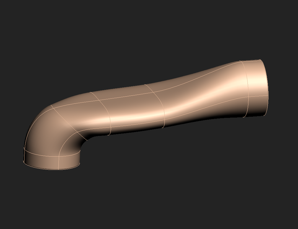
Compared to the last version:
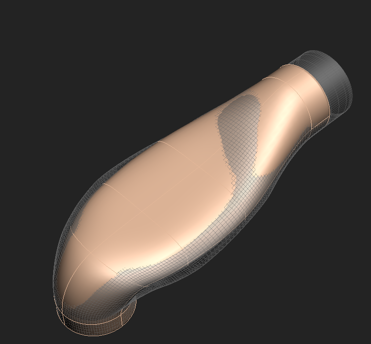
Another small detail. I also adjusted this design to be a more viable option for over the radiator intercooler piping. I would probably throw an extra layer of carbon into those and I would want to use a resin with a TG closer to 250F. It should be doable at only a small cost difference (maybe 10%?)
Lay up two halves under vacuum (this is the easy part)
->Oven cure for 12 hours
Trim flanges by hand
Place halves back into mold and tack corners with epoxy
->Oven cure for 6-8 hours
Fill gap with hysol 1c
-> Oven cure for 6 hours
Sand joint smooth to about 200 grit
Laminate strips of carbon over joint and vac bag
-> Oven cure for 12 hours
Hand sand and polish final part
There is a ton of hand trimming and sanding and parts have to wait on 4 epoxy cure cycles.
On the new redesign I have used up the available space better- The flat section is thicker and less wide. I also modeled it with surfaces so it can go into cad software easily. The plan is to move the process over to some machined aluminum or fiberglass molds and then bladder mold biaxial sleeves in one shot. No joining, minimal trimming, one epoxy cure cycle.
Compared to the last version:
Another small detail. I also adjusted this design to be a more viable option for over the radiator intercooler piping. I would probably throw an extra layer of carbon into those and I would want to use a resin with a TG closer to 250F. It should be doable at only a small cost difference (maybe 10%?)
Last edited by Joe Perez; 02-03-2016 at 06:54 PM. Reason: Put the comparison image inline
Reply
3
3
02-03-2016, 06:52 PM
#309
Newb

Join Date: Oct 2015
Location: Columbus, Ohio
Posts: 20
Total Cats: 4
Working link to .stl file? A local group in Ohio wants me to run a few prototypes at our University Lab that I currently work in. We have a dimension 1200 and Uprint(both ABS with heated chambers), a projet and a connex (polyjet), a smaller abs printer, a nylon printer with carbon, kevlar, and fiberglass inlay, and finally, an SLS printer.
Thanks!
-Josh
Thanks!
-Josh
Reply
0
0
02-03-2016, 07:27 PM
#310
It's on the thread. Look for it, he has several updates, find the last one and the link works
Working link to .stl file? A local group in Ohio wants me to run a few prototypes at our University Lab that I currently work in. We have a dimension 1200 and Uprint(both ABS with heated chambers), a projet and a connex (polyjet), a smaller abs printer, a nylon printer with carbon, kevlar, and fiberglass inlay, and finally, an SLS printer.
Thanks!
-Josh
Thanks!
-Josh
Reply
0
0
02-05-2016, 06:18 PM
#313
I just got my 3d intake and I am about to install it. However, I dont have that round hole in my car. I bought a 3" hole saw, the one on the passenger side is 2.75". Should I return it and get a 2.75" hole saw or will the extra room help the intake move with engine movement and not crack?
Reply
0
0
02-10-2016, 11:47 PM
#315

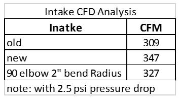
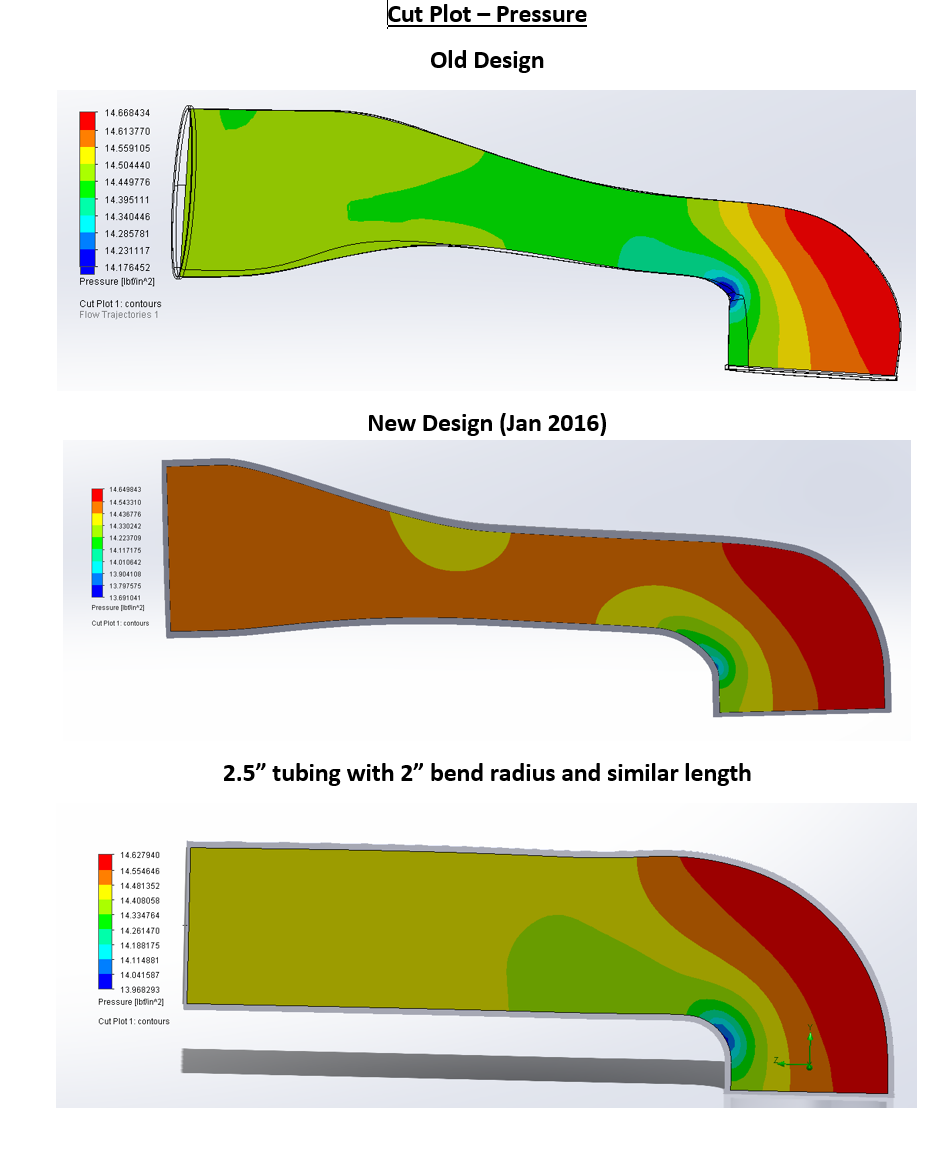
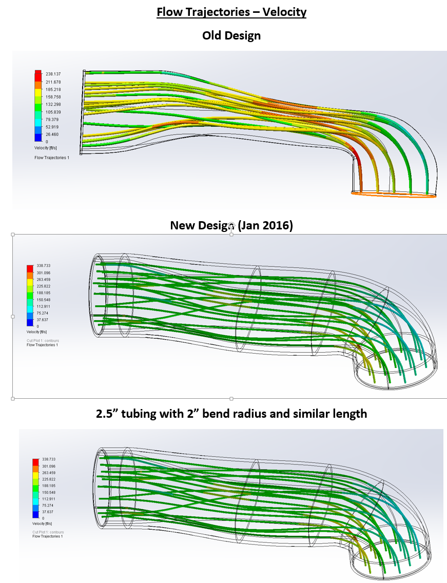
I finally got around to running the CFD. The new tube is much improved over the old tube. I compared it to a traditional 90 of the same diameter tube (2.5") since I was curious. This new tube even outflows that!
The CFM numbers speak for itself and give a good summary of the new design which flow 12% better for a set 0.25 PSI pressure drop.
NOTE: RUN AT 0.25 PSI! Not 2.5 PSI (I will edit this pics when I get home).
The best plot to see the differences between the tubes is the velcoity plot. All of the tubes show higher velocity around the bend. But the new design does the best job of keep the velocity consistent throughout the tube, especially around the bend. It's a major improvement over the old design.
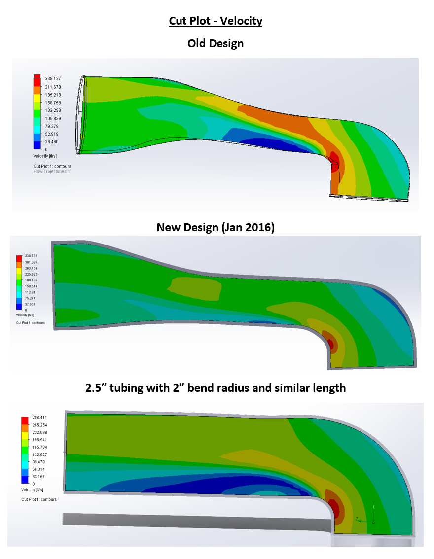
Here are the pressure and flow tragector plots just for the hell of it.
The CFM numbers speak for itself and give a good summary of the new design which flow 12% better for a set 0.25 PSI pressure drop.
NOTE: RUN AT 0.25 PSI! Not 2.5 PSI (I will edit this pics when I get home).
The best plot to see the differences between the tubes is the velcoity plot. All of the tubes show higher velocity around the bend. But the new design does the best job of keep the velocity consistent throughout the tube, especially around the bend. It's a major improvement over the old design.
Here are the pressure and flow tragector plots just for the hell of it.
Last edited by cyotani; 02-11-2016 at 10:21 AM.
Reply
9
9

 02-11-2016, 07:52 AM
#319
Senior Member
Thread Starter
iTrader: (1)
Join Date: Jul 2012
Location: durham NC
Posts: 792
Total Cats: 143
Awesome results. I guess the clean sheet design was worth it. A naturally aspirated miata engine is never going to flow close to 350 CFM. An online calculator says a engine with 2000cc displacement at 8500rpm and VE of 110 would be consuming 240 cfm.
Yeah, I probably need a name for it. I was thinking just Durham Composite intake.
Also, everyone should be giving cyotani props for doing CFD for me.
Yeah, I probably need a name for it. I was thinking just Durham Composite intake.
Also, everyone should be giving cyotani props for doing CFD for me.
Last edited by asmasm; 02-11-2016 at 08:40 AM.
Reply
0
0


