
cam cover blowby flow and crankcase pressure, tiny hole modification
 01-03-2011, 11:22 PM
#1
Elite Member
Thread Starter

Join Date: Jul 2005
Posts: 6,420
Total Cats: 84
I noticed slight weeping of oil into my compressor outlet when I drive the car hard. 10 psi GT2560 setup. I checked the crankcase pressure by connecting a Magnehelic pressure gauge to my dipstick tube with a hose - I get 12"-15" H20 at full power, even though the blowby flow out the cam cover breather was well within acceptable limits, by using a flow gauge.
2001 Engine is freshly rebuilt and broken in, and compression and leakdown are all good.
So something is restricting the flow, causing higher than acceptable crankcase pressure. I think I saw somewhere that it should be below 10". Perhaps too my turbo is a wee bit weepy and prefers to have less crankcase pressure. This crankcase pressure appears as a backpressure to the oil drain line, and thus drainage isn't good during hi boost operation, causing the weeping.
I examined the blowby baffling under the cam cover and saw that during boosted operation, all the blowby flows through a 1/4" hole. I plan to enlarge this hole, and possibly bore out the breather hole and enlarge the barb and hose to 1/2", up from 3/8". Ditto for the port it connects to between the air cleaner and the compressor inlet. FWIW on my E36 M3, the breather hose is at least 1/2", for a 240 hp factory rated motor. (see here: https://www.miataturbo.net/showpost....&postcount=125)
I had already done this mod (enlarging the 1/4" hole) before on my tired old 99 engine and it reduced the crankcase pressure during full power operation.
Last edited by JasonC SBB; 01-03-2011 at 11:55 PM.

Reply
 0
0

0
01-03-2011, 11:26 PM
#2
Elite Member
Thread Starter
Join Date: Jul 2005
Posts: 6,420
Total Cats: 84
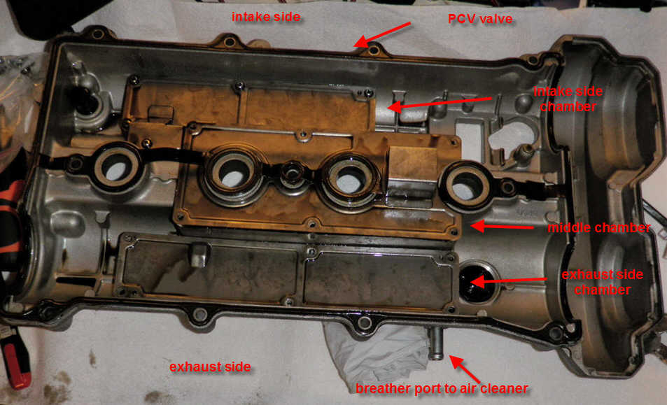
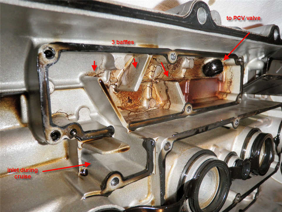
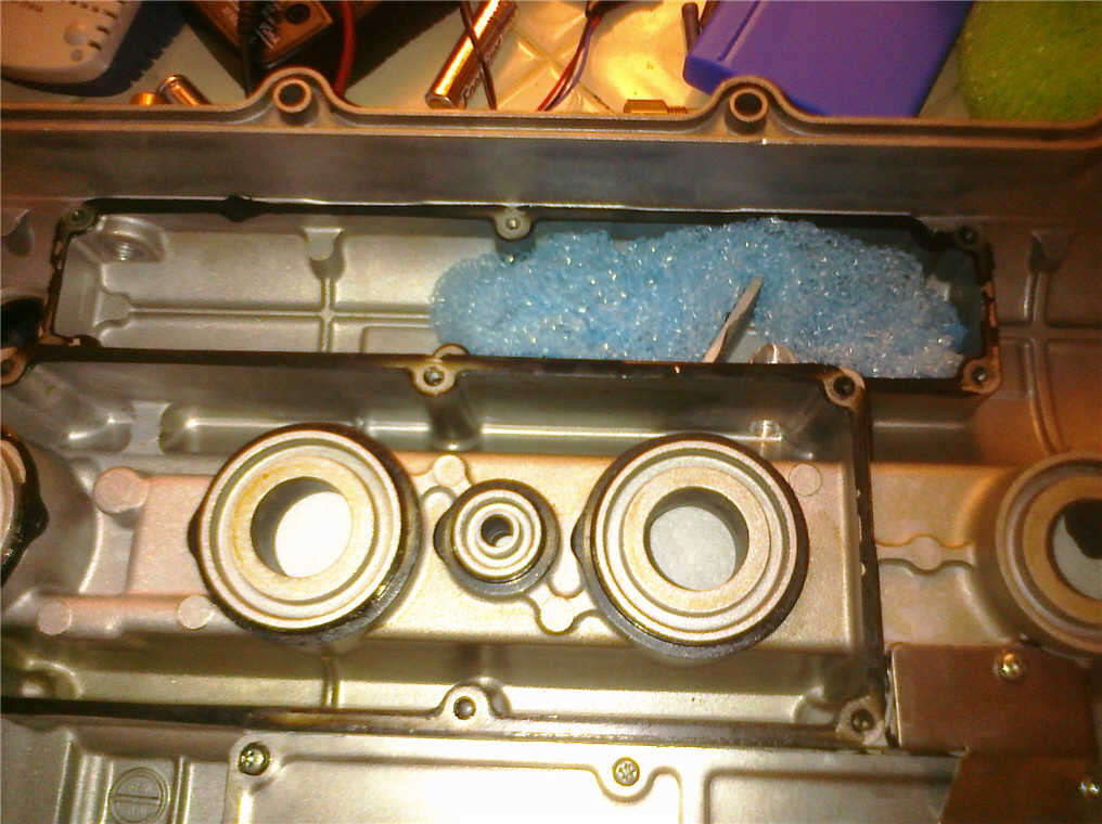
See photo of underside of cam cover. See 3 baffle chambers. Intake side, exhaust side, and center. I had already removed the screws holding the cover of the middle chamber.
The covers are held down with RTV. It helped to slit it where I could, before prying the covers up. Be careful to minimize the distortion of the covers, because you will have to flatten them else they may leak.
The covers are held down with RTV. It helped to slit it where I could, before prying the covers up. Be careful to minimize the distortion of the covers, because you will have to flatten them else they may leak.
Reply
0
0
 01-03-2011, 11:32 PM
#4
Elite Member
Thread Starter
Join Date: Jul 2005
Posts: 6,420
Total Cats: 84
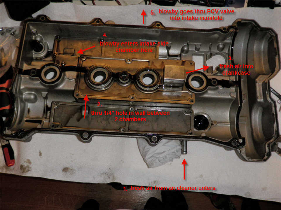
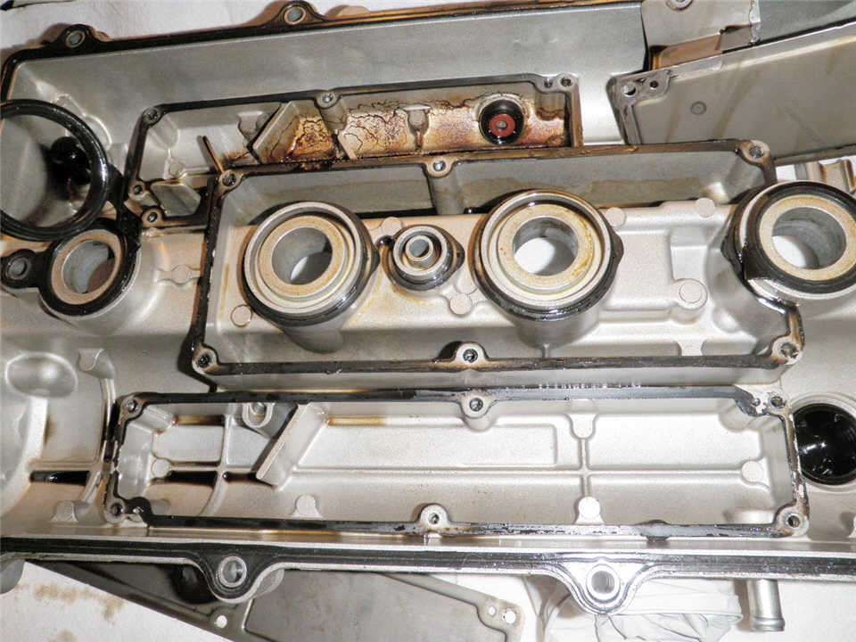
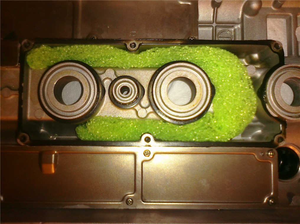
Here is the flow during cruise.
Note that any oil caught in the center baffle / chamber during high power operation, can drain back out the inlet of the middle chamber. (it's an inlet during high power operation)
Note that any oil caught in the center baffle / chamber during high power operation, can drain back out the inlet of the middle chamber. (it's an inlet during high power operation)
Reply
0
0
01-03-2011, 11:34 PM
#5
Elite Member
Thread Starter
Join Date: Jul 2005
Posts: 6,420
Total Cats: 84
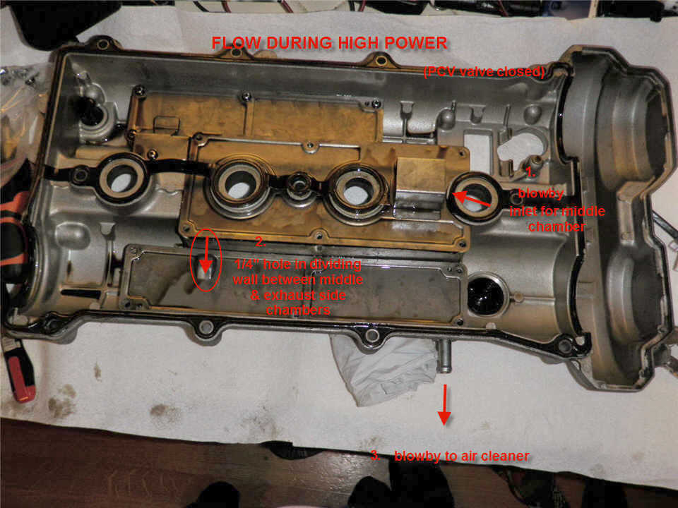
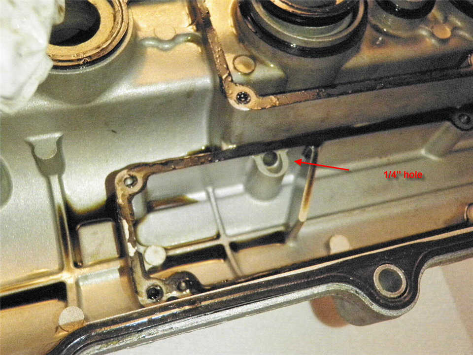
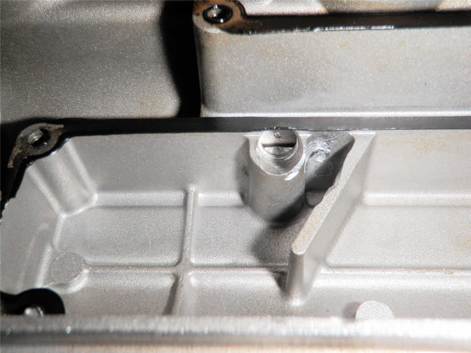
Here is the closeup of the 1/4" hole through which the blowby is forced.
Note that any oil trapped in the exhaust side chamber has to be slurped through this hole, sucked back into the middle chamber, for it to drain back into the cam box. This hole comes down to the "floor" of the exhaust side chamber, so it's at a low point. The breather is at a high point so liquid oil that floods here will not go out there.
I will take this to a machine shop and have the hole enlarged to at least 3/8", and possibly have a 2nd hole added. The angle of the drill is awkward due to the shape of the chambers, such that I can't do it with a drill. The machine shop will have to hold the cam cover somehow and have the drill bit come in at an angle.
Because the slurping effect will be reduced, I will have to add plastic kitchen scrubbers in the center chamber to reduce the amount of oil that gets to the exhaust side chamber.
Last edited by JasonC SBB; 01-03-2011 at 11:45 PM.
Reply
0
0

 )
) 01-03-2011, 11:40 PM
#7
Elite Member
Thread Starter
Join Date: Jul 2005
Posts: 6,420
Total Cats: 84
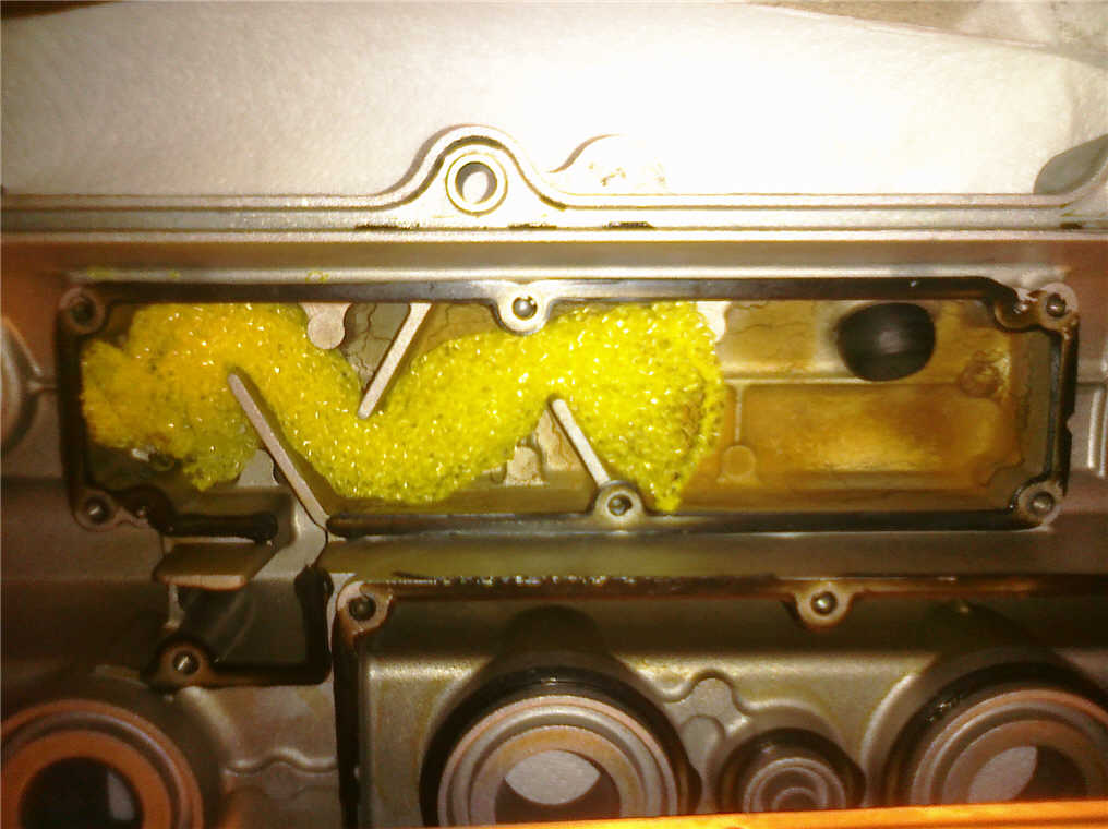
Here's the intake side chamber, cover removed.
Note it does not have a direct connection to the middle chamber.
It has 3 baffles, and oil trapped there will drain out the inlet.
I plan to add plastic scrubbers in here.
Note it does not have a direct connection to the middle chamber.
It has 3 baffles, and oil trapped there will drain out the inlet.
I plan to add plastic scrubbers in here.
Reply
0
0


 01-04-2011, 11:47 AM
#14
Elite Member
Thread Starter
Join Date: Jul 2005
Posts: 6,420
Total Cats: 84
https://www.miataturbo.net/showpost....0&postcount=85
And his reply to himself:
https://www.miataturbo.net/showpost....&postcount=102
I made a newer version with much less scrubber material which is away from the out ports - seems to be working. Catch can was almost empty after a day of racing. Also don't make any drain holes in the baffle covers regardless what some say.
I think I made pictures - will have to find those and post later.
P.S. Another thing is to make sure the baffle covers are well sealed with some gasket maker but I assume most already know that.
I think I made pictures - will have to find those and post later.
P.S. Another thing is to make sure the baffle covers are well sealed with some gasket maker but I assume most already know that.
Last edited by JasonC SBB; 01-04-2011 at 11:58 AM.
Reply
0
0
 01-04-2011, 12:34 PM
#16
Elite Member
iTrader: (2)

Join Date: Jan 2007
Location: Los Angeles, CA
Posts: 8,682
Total Cats: 130
Thanks for the pics of the VVT cover. I too have a VVT head and have to do something about my venting system.
I am thinking about reaming out the PCV and breather pipes and welding on -12 fittings to connect up to a VTA catch can with a manual drain. The 1/4" slurp hole will be reamed to 3/4", maybe an inch? No scrubbers.
I am thinking about reaming out the PCV and breather pipes and welding on -12 fittings to connect up to a VTA catch can with a manual drain. The 1/4" slurp hole will be reamed to 3/4", maybe an inch? No scrubbers.
Reply
0
0

 01-10-2011, 11:22 AM
#20
Elite Member
Thread Starter
Join Date: Jul 2005
Posts: 6,420
Total Cats: 84
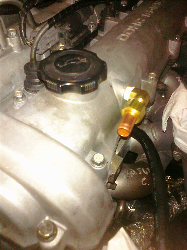
Here is my new breather port on the valve cover. The hole is 1/4th NPT, I have an elbow with a 1/2" pipe compression fitting. I used a short length of 1/2" copper pipe. Ignore the original 3/8" breather hose lying there under it:
Reply
0
0


