
KL-DE powered sand-rail

 07-08-2010, 02:38 PM
#42
Senior Member
Thread Starter
iTrader: (1)

Join Date: Aug 2006
Location: Illinois
Posts: 1,011
Total Cats: 7
Inferno is right. A spacer was used. I'm not too keen on that idea. It would seem to me that the farther away the flywheel is from the rear bearing journal, the more accuratly aligned and balanced it would need to be. Your 'extending the lever' by moving the flywheel away from it but I've seen worse thing ideas hold. Like the brake disc I'm about to use as a rear wheel adaptor. 

Reply
 0
0

0
07-09-2010, 12:23 AM
#43
Senior Member
Thread Starter
iTrader: (1)
Join Date: Aug 2006
Location: Illinois
Posts: 1,011
Total Cats: 7
I finished another engine mount and started welding on the a-arm mounts. Once those are set in place I can finish the upper strut mounts, tie in the brakes, run exhaust, then it's test drive time. Once I'm satisfied it drives right I'll button things up like the ECU box and a new instrument cluster. The cluster in it now gets in the way of my leg. I'm going to mount a new one centered just below the windshield with the gauges in a horizontal row. It'll be about 4" tall and 14" wide. When I did the wiring harness I put in enough wires to cover things like the factory speed sensor for an electronic speedo, an alternator light, a check engine light (working and no CEL yet), and electronic oil pressure and temp gauges using the OEM Mazda sensors. As simple as this vehicle may seem, there's an aweful lot of wiring ran through the chassis but at least it's hidden away in the tubing.
I'm aiming to have this driving by thie end of this weekend.
Once I'm satisfied it drives right I'll button things up like the ECU box and a new instrument cluster. The cluster in it now gets in the way of my leg. I'm going to mount a new one centered just below the windshield with the gauges in a horizontal row. It'll be about 4" tall and 14" wide. When I did the wiring harness I put in enough wires to cover things like the factory speed sensor for an electronic speedo, an alternator light, a check engine light (working and no CEL yet), and electronic oil pressure and temp gauges using the OEM Mazda sensors. As simple as this vehicle may seem, there's an aweful lot of wiring ran through the chassis but at least it's hidden away in the tubing.I'm aiming to have this driving by thie end of this weekend.
Reply
0
0
07-09-2010, 01:58 AM
#44
Senior Member
Thread Starter
iTrader: (1)
Join Date: Aug 2006
Location: Illinois
Posts: 1,011
Total Cats: 7
Here's some pics of what's been happening.
1st is the shifter. It was from a Mazda Protege. I cut off the bottom pivot and welded it to a plate to make it easy to bolt to anything I want.It was turned 45deg to clear existing holes. It will be corrected later.
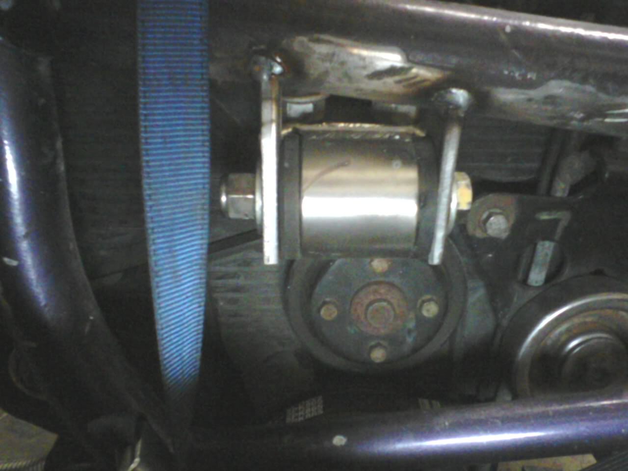
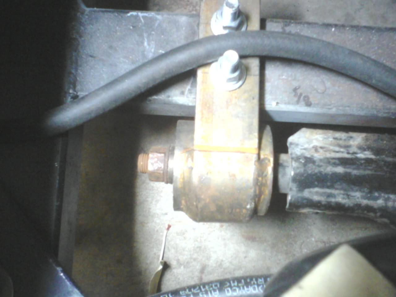
2nd is the motor mount on the front of the engine. It bolts to the stock Mazda engine bracket and uses poly inserts.
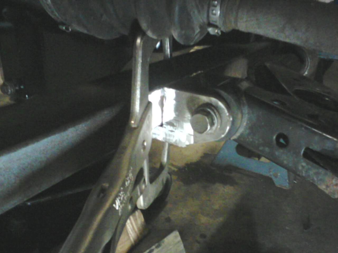
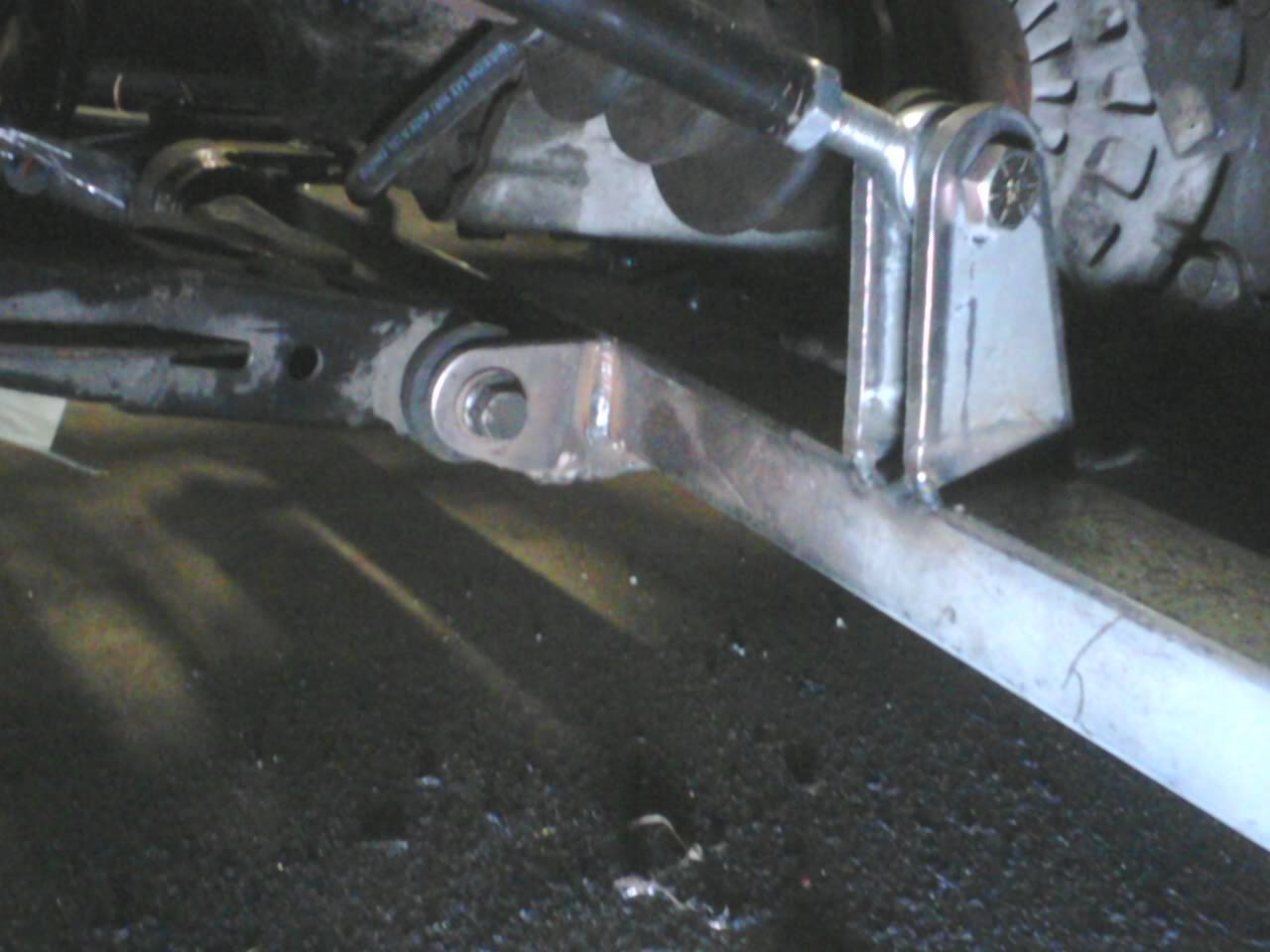
3rd is one of the 2 lower control arm mounts. It wraps under the subframe and uses the 626 control arms.
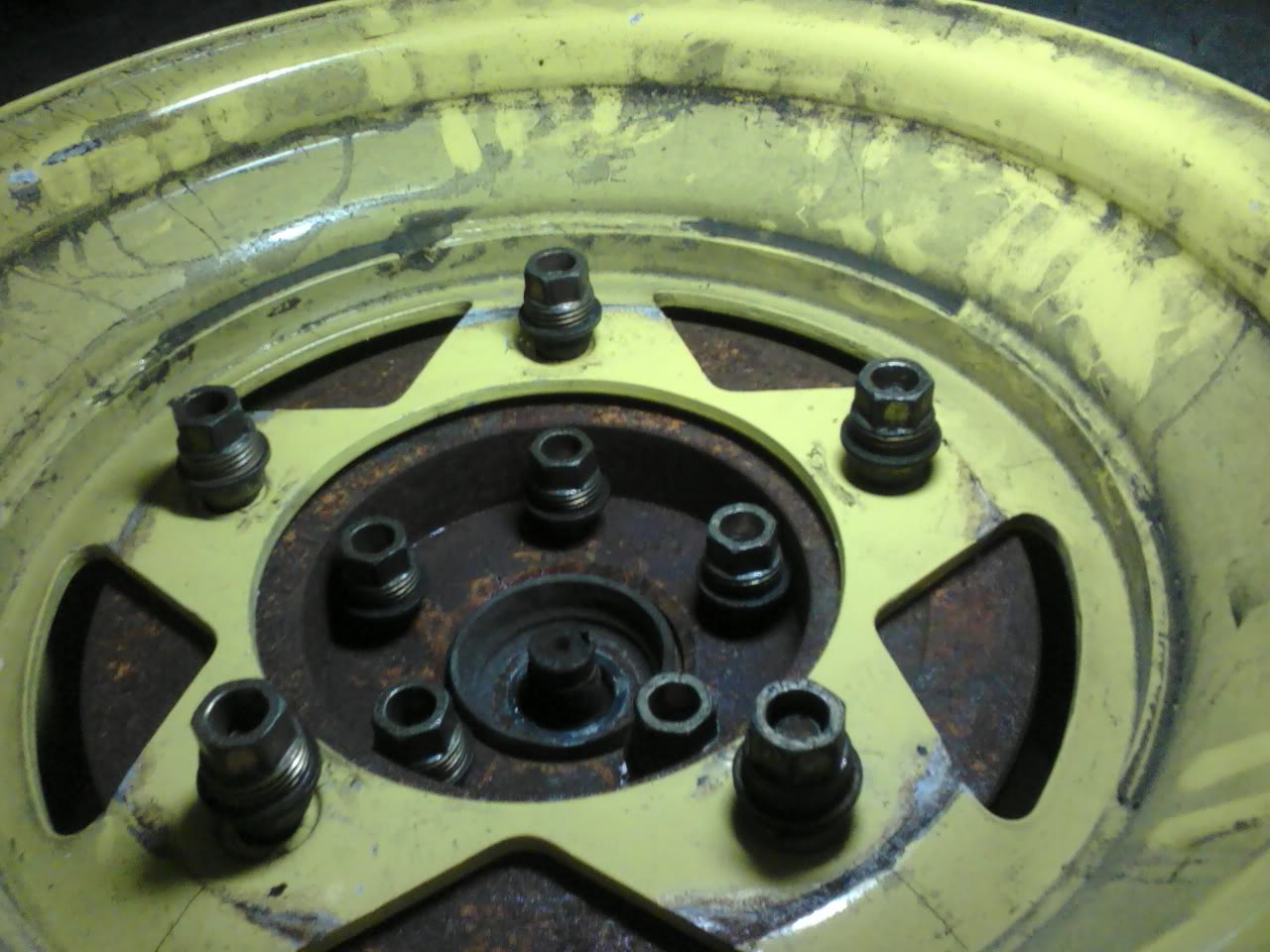
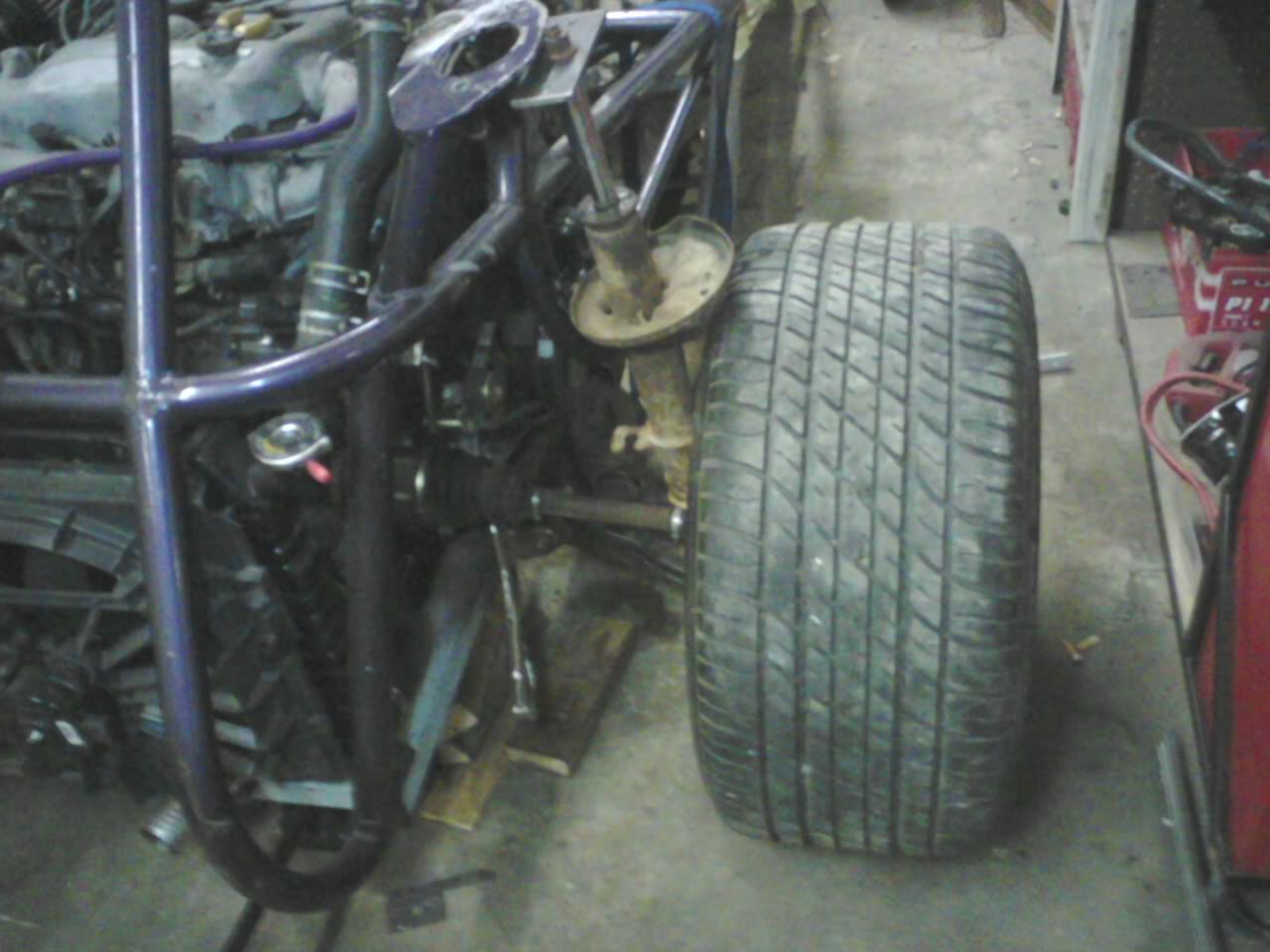
4th is my favorite. I used the rear rotor from the 626 to make an adaptor for the VW 5-bolt rear wheels. It's pretty darn straight considering I don't have a lathe or mill. I used an old front spindle/hub and clamped in the vise. Then I found a spacer to center a bolt through the axle hole and spun it with a cordless drill with a socket attachment. I used a pick to scribe an 8" circle on the rusty disc. I eyeballed each lug stud in line with the center of the hub and put a dot on my circle. I did this 5 times then drilled the disc and pounded in the lug studs from the old hub. I mounted the wheel backwards because it stuck out too far due to the offset. I'll have proper spacers made before this sees highway speeds.
And finally, the wheel attached to the hub.
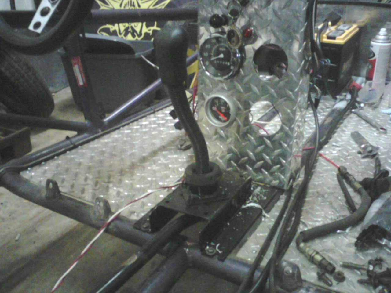
1st is the shifter. It was from a Mazda Protege. I cut off the bottom pivot and welded it to a plate to make it easy to bolt to anything I want.It was turned 45deg to clear existing holes. It will be corrected later.
2nd is the motor mount on the front of the engine. It bolts to the stock Mazda engine bracket and uses poly inserts.
3rd is one of the 2 lower control arm mounts. It wraps under the subframe and uses the 626 control arms.
4th is my favorite. I used the rear rotor from the 626 to make an adaptor for the VW 5-bolt rear wheels. It's pretty darn straight considering I don't have a lathe or mill. I used an old front spindle/hub and clamped in the vise. Then I found a spacer to center a bolt through the axle hole and spun it with a cordless drill with a socket attachment. I used a pick to scribe an 8" circle on the rusty disc. I eyeballed each lug stud in line with the center of the hub and put a dot on my circle. I did this 5 times then drilled the disc and pounded in the lug studs from the old hub. I mounted the wheel backwards because it stuck out too far due to the offset. I'll have proper spacers made before this sees highway speeds.
And finally, the wheel attached to the hub.
Reply
0
0
07-09-2010, 07:59 AM
#45
The more I see of this the more I think 'Im-a git me one-a doze'. In other words great work, very...resourceful.
Now if you could only tell me how to get the crumbling to pieces (yet corroded in) vss out of my brother's protege you would be my second favourite person today.
Now if you could only tell me how to get the crumbling to pieces (yet corroded in) vss out of my brother's protege you would be my second favourite person today.
Reply
0
0
07-09-2010, 02:55 PM
#46
Senior Member
Thread Starter
iTrader: (1)
Join Date: Aug 2006
Location: Illinois
Posts: 1,011
Total Cats: 7
The more I see of this the more I think 'Im-a git me one-a doze'. In other words great work, very...resourceful.
Now if you could only tell me how to get the crumbling to pieces (yet corroded in) vss out of my brother's protege you would be my second favourite person today.
Now if you could only tell me how to get the crumbling to pieces (yet corroded in) vss out of my brother's protege you would be my second favourite person today.
Reply
0
0
07-11-2010, 10:20 PM
#48
Senior Member
Thread Starter
iTrader: (1)
Join Date: Aug 2006
Location: Illinois
Posts: 1,011
Total Cats: 7
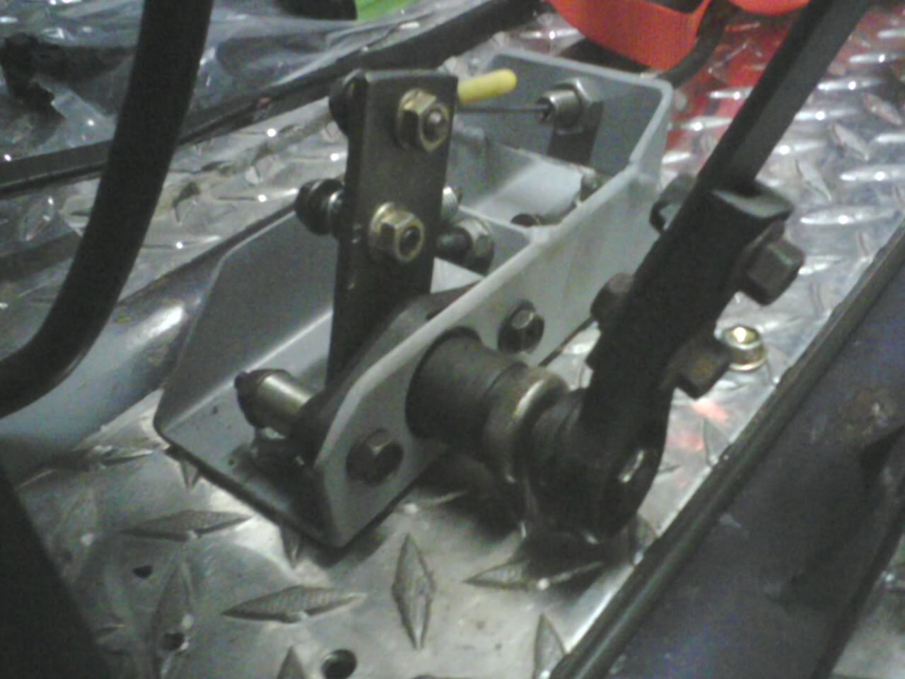
Here's the new air pedal. I'd call it a gas pedal but that's WRONG! lol It has a stopper so when your WOT it's not pulling against the stop on the throttle body and putting stress on the cable. It also has a back stop to make the range from closed to WOT adjustable. The pedal arm itself can be adjusted to change your foot position and the cable itself is adjustable to remove the slack both at the pedal assembly and at the throttle body. yeah custom \/
Can anyone guess what it's made from?
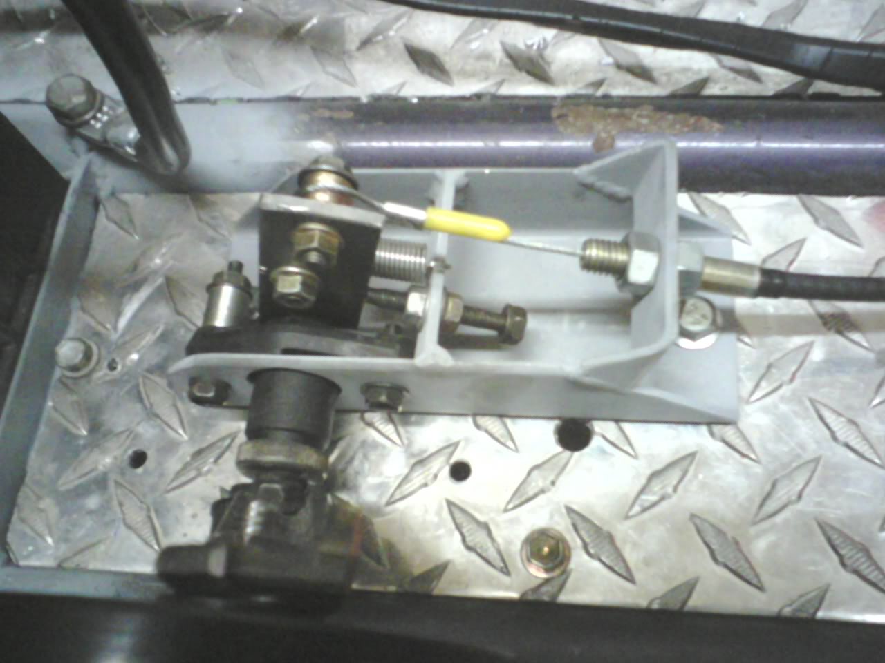
Guess correctly and win this cookie!

/Can anyone guess what it's made from?
Guess correctly and win this cookie!
Last edited by lazzer408; 07-12-2010 at 01:09 AM.
Reply
0
0
07-12-2010, 06:10 AM
#49
Senior Member
Thread Starter
iTrader: (1)
Join Date: Aug 2006
Location: Illinois
Posts: 1,011
Total Cats: 7
Started the strut plates tonight. It's going to take alot of measuring to get them in the right place. My main concern is camber since there's no camber adjustment. I'll weld them in as close to zero as I can then put cam bolts in the lower strut mounts for camber adjustment. The height of the mount will leave 1" of chassis ground clearance when the strut hits the bump stop. I've trimmed the bump stops so the mount doesn't have to be as high as if I left them stock.
Reply
0
0


 07-13-2010, 12:56 AM
#60
Senior Member
Thread Starter
iTrader: (1)
Join Date: Aug 2006
Location: Illinois
Posts: 1,011
Total Cats: 7
Here's a few more pics. My phone doesn't shoot video apperently so that will have to wait until tomorrow.
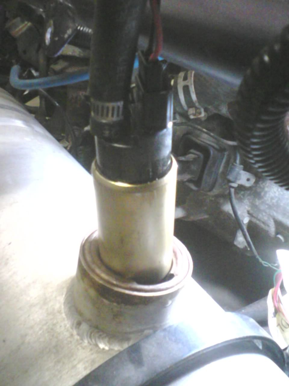
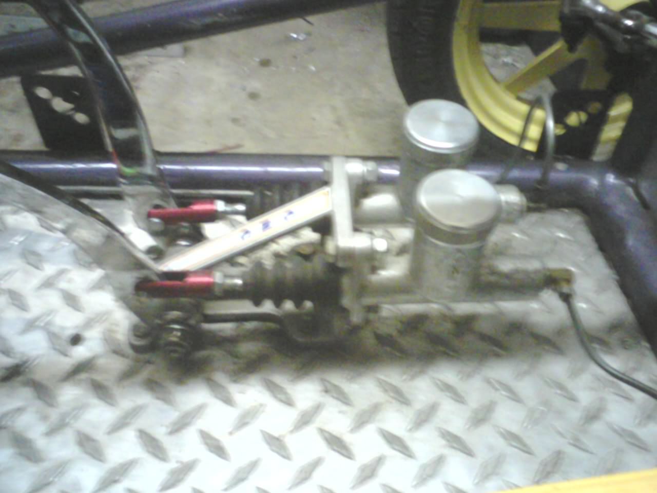
The Miata fuel pump fit down the filler neck of the gas tank so I used it temporarily. Also shot of the lower control arm mounts. For the front mount I welded in 2 solid round tubes in the subframe rail so it wasn't crushed when tightened. I did the same thing where the subframe attaches to the main chassis. Heim links are used to hold the toe straight since the spindles used to steer the 626. Then my brake and clutch pedals. The original owner ran the lines under the frame. I moved them above the frame so they won't get damaged. It only has rear brakes so failure is not an option. I'd like to see if the 626 rear calipers/brackets would fit the front spindles. If so, I'll be able to hook up an e-brake.
EDIT - I finished the brake lines tonight. As soon as I get gas for the mig I'll be able to take it for a test drive.
Last edited by lazzer408; 07-13-2010 at 02:06 AM.
Reply
0
0


