
EWP (electric water pump)
 05-09-2016, 11:48 PM
#1
ʎpunq qoq
Thread Starter

Join Date: Jan 2014
Location: Western Australia
Posts: 604
Total Cats: 201
I'm setting up my engine to use an EWP instead of the mechanical pump. I'm doing this for a few reasons. More HP at high revs, better cooling in pits / idle, just cause I like making stuff and experimenting.
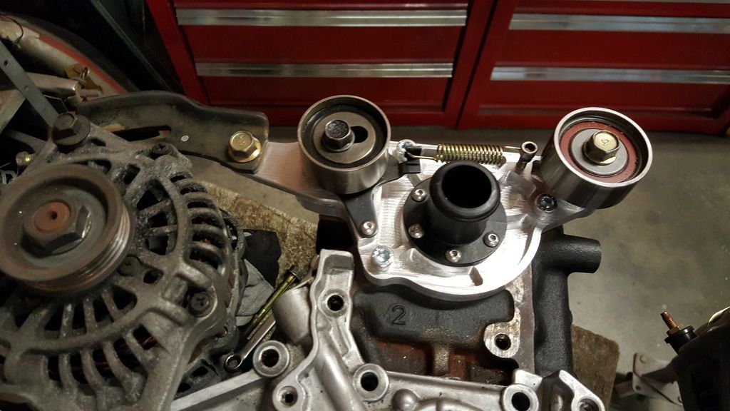
First task is to either blank off or replace the stock water pump. Since I like to over engineer stuff I figured I'd make a billet blank off plate. Not only does it look better, I can design it to move my alternator to the hot side via some custom mounts.
I started with a waterjet cut 22mm plate.
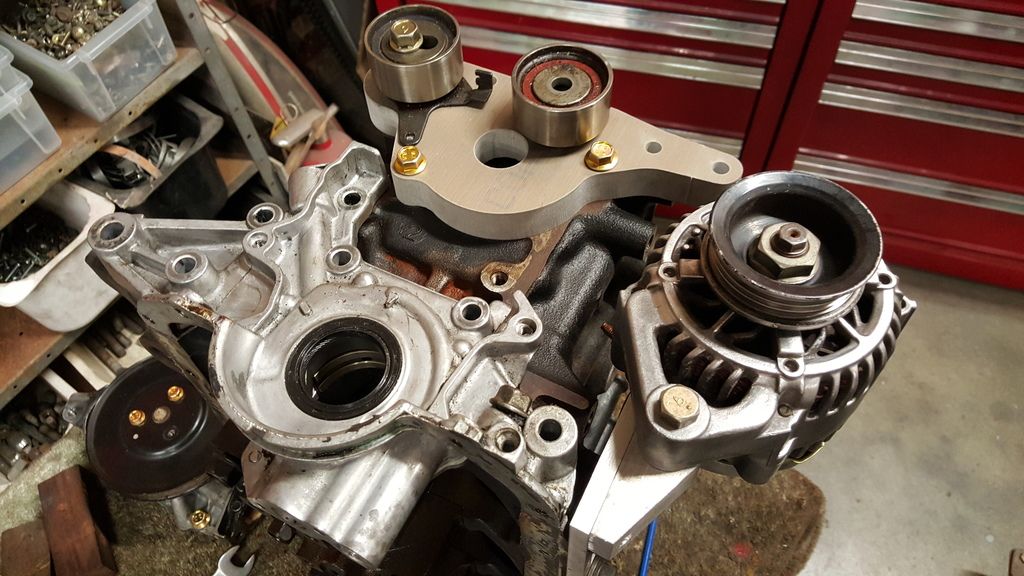
Then machined down the idler pulley and tensioner to 20mm. (I've moved the idler in 2mm so I can get some more belt tension due to my decked head). I also machined down the center to 12mm to take out some weight and for the mounting bolts to clear the belt / pulleys. This was done on my milling machine.
With a bit of filing and sanding most of the machining marks came out. The center mount is for the Davies Craig fittings. I need to figure out if I'm going to use silicon hose or go all out with 16AN fittings. The back of the output hole has a routed 10mm radius to help the waterflow.
All up it came out pretty good. You can see my small Suzuki alternator which I picked up from a wrecker. It even had the right 4rib pulley.
Next task is to make up a couple of plates to feed water into the front and back of the head.
First task is to either blank off or replace the stock water pump. Since I like to over engineer stuff I figured I'd make a billet blank off plate. Not only does it look better, I can design it to move my alternator to the hot side via some custom mounts.
I started with a waterjet cut 22mm plate.
Then machined down the idler pulley and tensioner to 20mm. (I've moved the idler in 2mm so I can get some more belt tension due to my decked head). I also machined down the center to 12mm to take out some weight and for the mounting bolts to clear the belt / pulleys. This was done on my milling machine.
With a bit of filing and sanding most of the machining marks came out. The center mount is for the Davies Craig fittings. I need to figure out if I'm going to use silicon hose or go all out with 16AN fittings. The back of the output hole has a routed 10mm radius to help the waterflow.
All up it came out pretty good. You can see my small Suzuki alternator which I picked up from a wrecker. It even had the right 4rib pulley.
Next task is to make up a couple of plates to feed water into the front and back of the head.
Last edited by Madjak; 05-09-2016 at 11:58 PM.

Reply
 5
5

5
 05-10-2016, 12:53 AM
#3
ʎpunq qoq
Thread Starter
Join Date: Jan 2014
Location: Western Australia
Posts: 604
Total Cats: 201
Yeah I'll run reverse flow. I'm thinking of running a 16AN line to the back of the head (1" ID) and a 12AN to the front (3/4" ID). I think you need to run intakes on both ends to reduce the chance of air bubbles being trapped in the head.
The alternator is on the hot side so that I have better access to the oil lines / filter and also to move some weight to the passenger side (I'm RHD). As a bonus, I figure the existing alternator spot is ideal for a low mount Rotex.
The alternator is on the hot side so that I have better access to the oil lines / filter and also to move some weight to the passenger side (I'm RHD). As a bonus, I figure the existing alternator spot is ideal for a low mount Rotex.
Reply
0
0
 05-10-2016, 06:50 AM
#5
ʎpunq qoq
Thread Starter
Join Date: Jan 2014
Location: Western Australia
Posts: 604
Total Cats: 201
I'm not planning to re-dyno the car so I won't be able to confirm any power gains. Supposedly at 8000+ RPM the stock water pumps can sap up to 10HP or the other theory is that they cavitate and don't circuilate the coolant effectively. I'm not sure on either claim but my guess is that there is 2-4 HP in it maybe.
I already don't run a thermostat so my cooling system won't really be any different except the coolant will cycle faster at idle and slower at high revs. Plus I'll be able to run the pump after the engine is shutdown and also pulse it when the coolant is cool... not that warmup is much of a problem for my car.I'll make a decision soon on whether I run silicon or AN hose but it will be a while until I plumb it all in as I'll have to wait for shipping.
I already don't run a thermostat so my cooling system won't really be any different except the coolant will cycle faster at idle and slower at high revs. Plus I'll be able to run the pump after the engine is shutdown and also pulse it when the coolant is cool... not that warmup is much of a problem for my car.I'll make a decision soon on whether I run silicon or AN hose but it will be a while until I plumb it all in as I'll have to wait for shipping.
Reply
0
0
05-10-2016, 12:26 PM
#6

Nice! I have been running a Davies Craig EWP 115 for 5-6 years now. It is awesome. Will you control the pump with your ECU, or use a dedicated EWP controller? I resisted using the EWP controller (also Davies Craig) at first, but it is a very good solution. The old style controller I have is just OK - the new display version seems better and I hope is a bit more robust (I have been through one, replaced under warranty). The EWP controller can vary the duty cycle on the pump, and its speed (voltage). The Davies Craig system is self-contained, meaning that the pump controller has its own thermostat, and also controls the cooling fan. My ECU no longer controls the pump and fan. When I come off the track hot and shut down, the pump and fan will continue to run until the water temperature reaches its set point. The set point can be adjusted by pushing a button on the controller. I never have cooling issues, except that on very cold days, my radiator & cooling ducts and vents are too effective (so I have to block them off).
I installed the EWP for the same reasons as you - high revving motor, potential pump cavitation, better cool-down, efficiency. I took the opportunity to completely remove the filler neck, re route the coolant hoses, and relocated the top coolant port on the radiator to the driver side, so the front of my engine is completely open, unblocked. Your setup looks very clean, too!
WIth such an efficient cooling system, radiator shutters (for aerodynamic improvement) could be a legit option!
Reply
1
1
05-18-2016, 10:07 PM
#7
ʎpunq qoq
Thread Starter
Join Date: Jan 2014
Location: Western Australia
Posts: 604
Total Cats: 201
Small update. I used to own a small 4-axis CNC machine that I sold off years ago. I still talk to the guy who purchased it as he's involved in motorsport and he said I could borrow it for a while. The machine has a bed size of 650 x 450 and a working height of up to 150mm. Plus it has a nice little rotary axis for smaller work.
Here is my first test cut from the machine. All up around 4 hours of cutting time into chemiwood. I'll pick up some aluminium stock today and make it for real over the weekend, which should take around twice as long to machine.
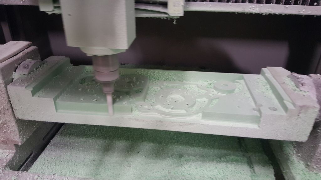
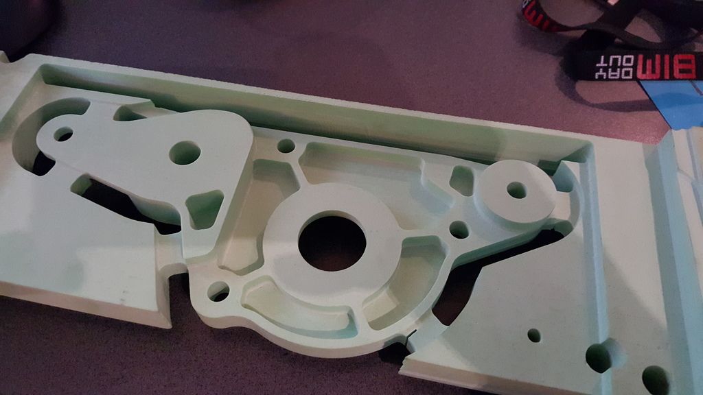
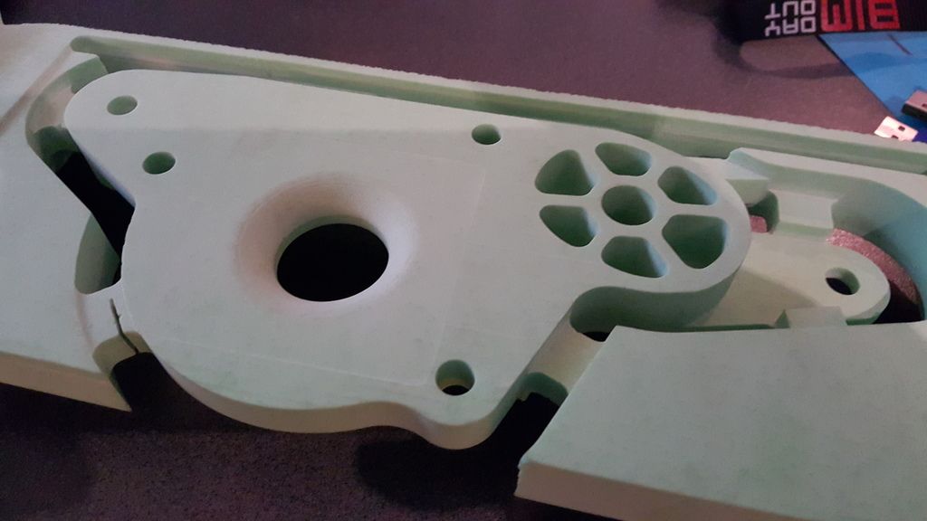
Here is my first test cut from the machine. All up around 4 hours of cutting time into chemiwood. I'll pick up some aluminium stock today and make it for real over the weekend, which should take around twice as long to machine.
Reply
3
3


 05-22-2016, 11:09 PM
#10
ʎpunq qoq
Thread Starter
Join Date: Jan 2014
Location: Western Australia
Posts: 604
Total Cats: 201
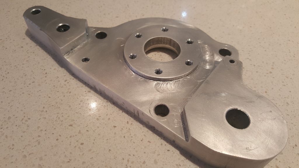
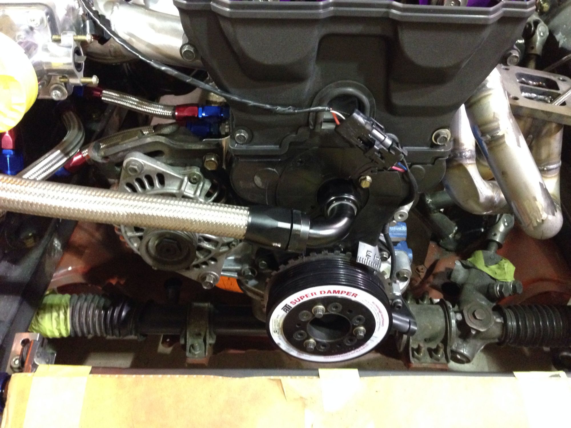
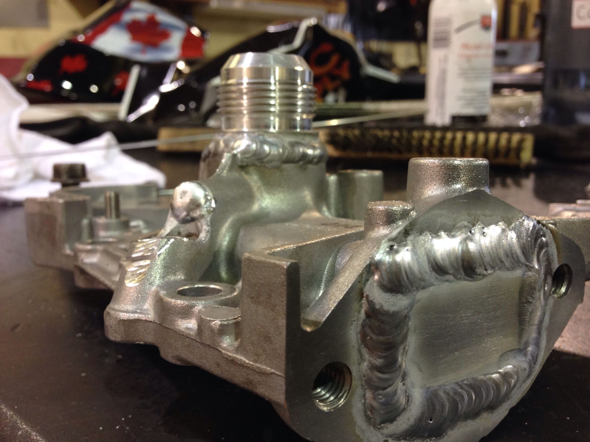
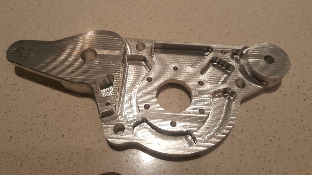
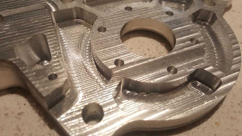
The billet aluminum water pump plate is now finished. All up the surface came up pretty nice and very smooth, with a few marks on the sides where I initially had the bit too far out of the collet causing chatter. The photos make it look rough but it's just the machining marks in the surface. I'll probably get this part anodized to protect it from the coolant.
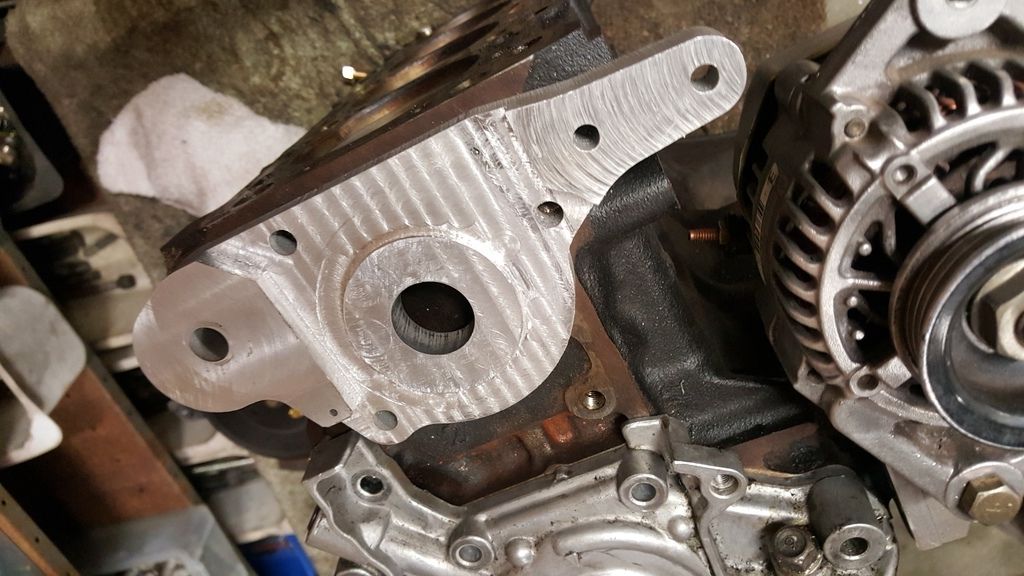
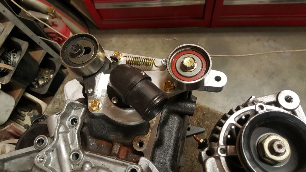
It all mounts up fine. Next part to machine is a manifold that connects to the Davies Craig water pump and outputs to 2 x 12AN lines for coolant to the head.
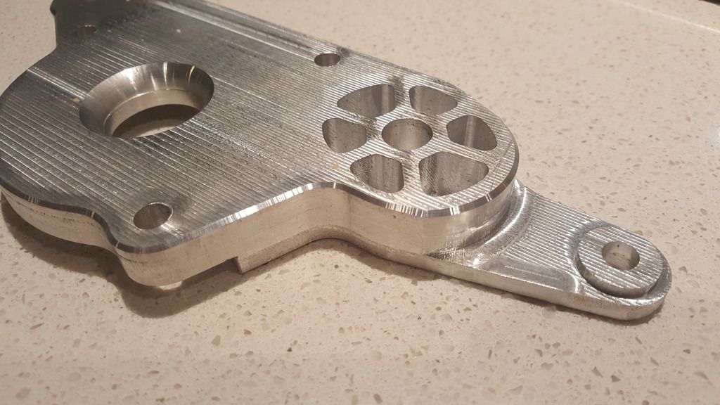
It all mounts up fine. Next part to machine is a manifold that connects to the Davies Craig water pump and outputs to 2 x 12AN lines for coolant to the head.
Reply
3
3

 05-23-2016, 02:48 PM
#16
Boost Pope


iTrader: (8)
Join Date: Sep 2005
Location: Chicago. (The less-murder part.)
Posts: 33,026
Total Cats: 6,592
Serious question:
The tab to which the upper alternator mount attaches seems kind of long and skinny, like it might tend to flex and eventually suffer fatigue failure. Is there a reason that part was made like that?
The tab to which the upper alternator mount attaches seems kind of long and skinny, like it might tend to flex and eventually suffer fatigue failure. Is there a reason that part was made like that?
Reply
0
0
05-23-2016, 10:04 PM
#17
ʎpunq qoq
Thread Starter
Join Date: Jan 2014
Location: Western Australia
Posts: 604
Total Cats: 201
I find its hard to judge size and thickness when modelling in 3D. I really need to hold the part in my hand, tap it and try and bend it before I get a good sense of where it's overdesigned or a potential weak point. Thats why custom design is so time consuming and expensive.
I'll probably get a run of 10 of these made at the machine shop that leant me the mill. I need to mount one up and test it all first to make sure it works as it should.
Im currently sorting out the other parts I need to finish the system. I'm not sure if anyone has run the coolant in a reverse flow direction so it will need some testing to see if its effective or not.
Reply
0
0
05-23-2016, 10:10 PM
#18
Boost Pope
iTrader: (8)
Join Date: Sep 2005
Location: Chicago. (The less-murder part.)
Posts: 33,026
Total Cats: 6,592
Good question... when I made the 3D model I figured 6mm would be thick enough. Now I have the part it feels and looks too thin so I'll add a triangular brace on the bottom. Its probably strong enough but since I cut it with an end mill there is a potential stress point where the tab joins the bulk of the part.
But nitpicking aside, this is phenomenal work.
Reply
0
0
05-23-2016, 11:01 PM
#19

Good question... when I made the 3D model I figured 6mm would be thick enough. Now I have the part it feels and looks too thin so I'll add a triangular brace on the bottom. Its probably strong enough but since I cut it with an end mill there is a potential stress point where the tab joins the bulk of the part.
I find its hard to judge size and thickness when modelling in 3D. I really need to hold the part in my hand, tap it and try and bend it before I get a good sense of where it's overdesigned or a potential weak point. Thats why custom design is so time consuming and expensive.
I'll probably get a run of 10 of these made at the machine shop that leant me the mill. I need to mount one up and test it all first to make sure it works as it should.
Im currently sorting out the other parts I need to finish the system. I'm not sure if anyone has run the coolant in a reverse flow direction so it will need some testing to see if its effective or not.
Reply
0
0
05-24-2016, 01:18 AM
#20
ʎpunq qoq
Thread Starter
Join Date: Jan 2014
Location: Western Australia
Posts: 604
Total Cats: 201
I don't know how you guys can even work in inches let alone design stuff! I suppose it's one of those things that you have to spend your life working in so you can memorize the sizing and learn the relationships. I find I tend to convert it back to decimal inches whenever I'm drawing things which makes it suit my more metric programmed brain.
For example 27/32" I have to spend a lot of time figuring it out if it's larger or smaller than 7/8" or 13/16".
For example 27/32" I have to spend a lot of time figuring it out if it's larger or smaller than 7/8" or 13/16".
Reply
0
0


