
Miata LFX Swap (Singular Motorsports & Good-Win Racing)
 07-13-2016, 12:00 PM
#301
Supporting Vendor

Thread Starter
iTrader: (3)

Join Date: Jul 2006
Location: San Diego
Posts: 3,303
Total Cats: 1,216
In the front, everything ties in together so I've spent a lot of time figuring out how I want to do things most efficiently. I don't want separate brackets for each part that needs to be mounted, the redundancy would just be more weight.
Everything is centered around the new cross-beam between the two frame rails. But, this time I made it bolt-in so it can be removed entirely for engine removal/install. Making it removable involved welding captive nuts inside the frame rails... that took some creative problem solving
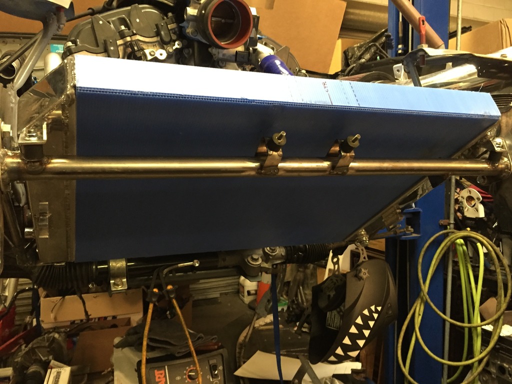
Here's the cross-bar. The radiator, intake, power steering cooler, and some of the air ducting will all tie into this:

The radiator's upper brackets mount to the two outer threaded points on the cross brace, via rubber standoffs to isolate vibrations:
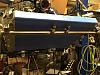
The center two tabs that you can see above are for the intake. Again, rubber standoffs used here to absorb the twist the engine will put on the intake. Here's a closer shot:
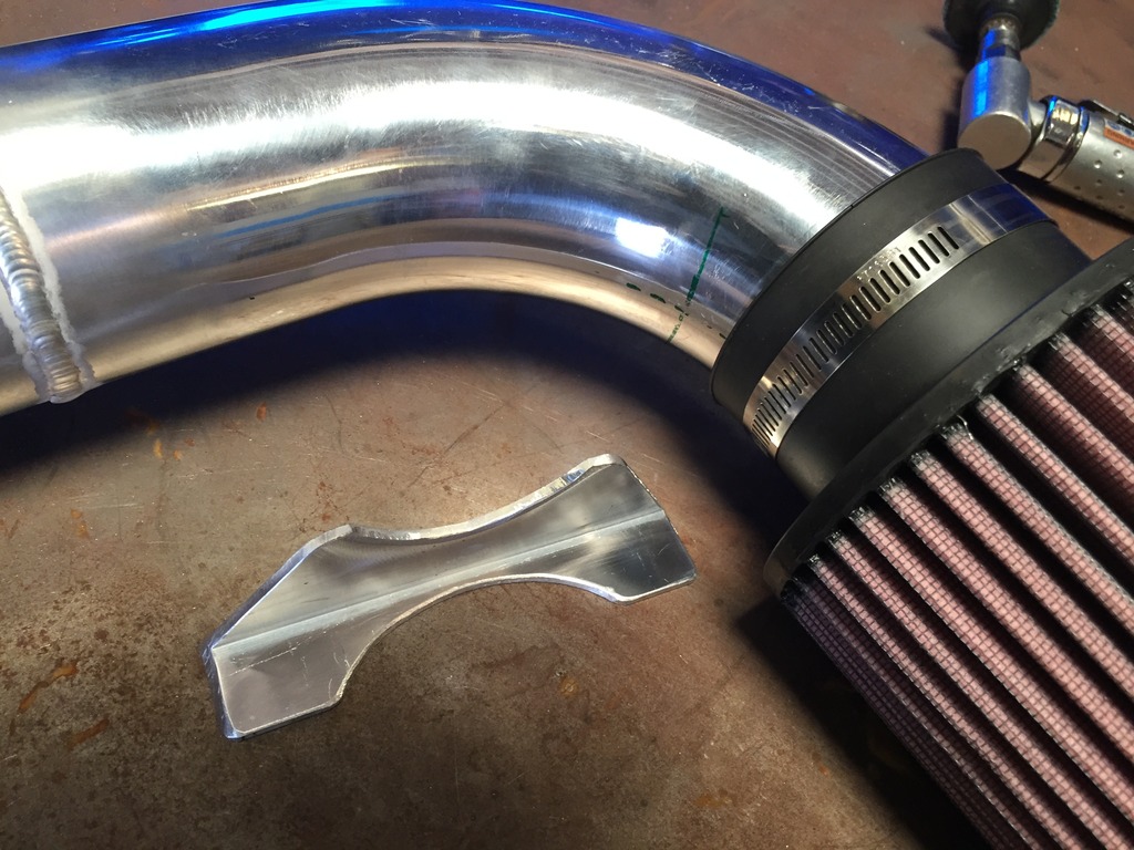
To mount the intake to those tabs took some more aluminum...
And some welding...

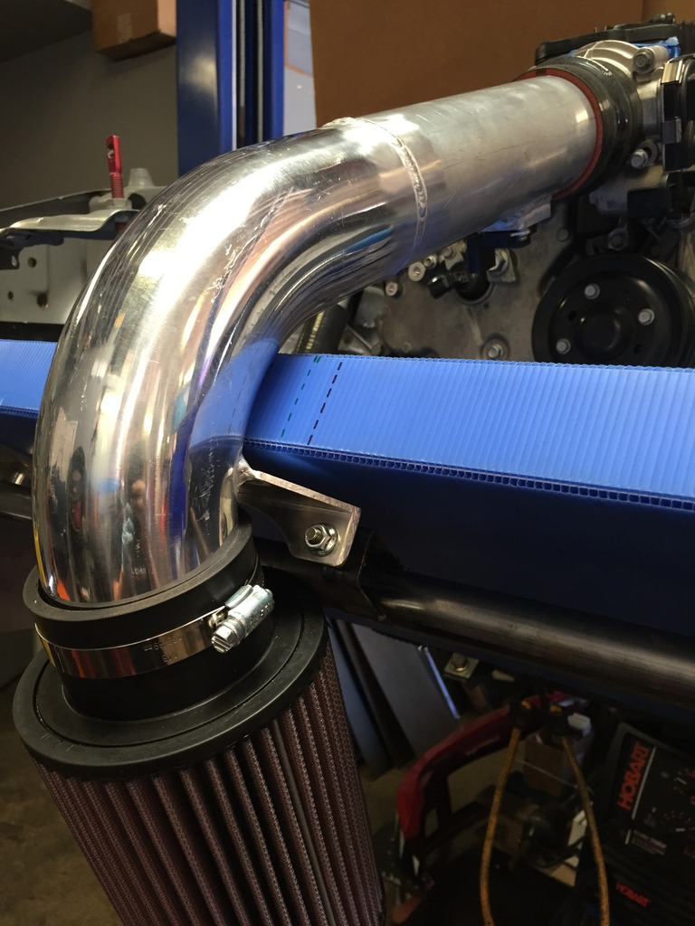
And the intake is officially done! The radiator is now fully mounted as well, and I also did the power steering cooler mounts, but will save that to post all at once when I cover the power steering system.
Now, before anyone starts asking about the filter location getting debris thrown at it through the bumper opening, don't worry - there are plans that tie in with the ducting that will take care of that.
Everything is centered around the new cross-beam between the two frame rails. But, this time I made it bolt-in so it can be removed entirely for engine removal/install. Making it removable involved welding captive nuts inside the frame rails... that took some creative problem solving
Here's the cross-bar. The radiator, intake, power steering cooler, and some of the air ducting will all tie into this:
The radiator's upper brackets mount to the two outer threaded points on the cross brace, via rubber standoffs to isolate vibrations:
The center two tabs that you can see above are for the intake. Again, rubber standoffs used here to absorb the twist the engine will put on the intake. Here's a closer shot:

To mount the intake to those tabs took some more aluminum...
And some welding...
And the intake is officially done! The radiator is now fully mounted as well, and I also did the power steering cooler mounts, but will save that to post all at once when I cover the power steering system.
Now, before anyone starts asking about the filter location getting debris thrown at it through the bumper opening, don't worry - there are plans that tie in with the ducting that will take care of that.


Reply
 2
2

2
07-14-2016, 12:23 AM
#302
Supporting Vendor
Thread Starter
iTrader: (3)
Join Date: Jul 2006
Location: San Diego
Posts: 3,303
Total Cats: 1,216
Coolant Return Line
The feed line from the engine to radiator has already been covered, that was pretty simple with just a couple 90� silicone bits and a straight joiner.
The return line back to the motor though needed a bit more attention. In the few LFX swaps that are out there so far, everyone's re-used a factory GM return line, but because I'm using an NC radiator which has the feed/return on the correct sides of the radiator to match the LFX (as oppose to NA/NB rads which are opposite), I could actually make use of the more direct and simplified routing that this makes possible. But, that means I need a new return line...
So, let's make one
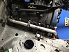
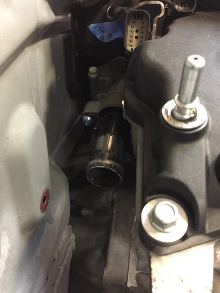
The only bit I wanted to re-use from the factory line was the very end that meets the motor - for its specific o-ring and mounting tab there. So, I cut that bit off and discarded the rest:

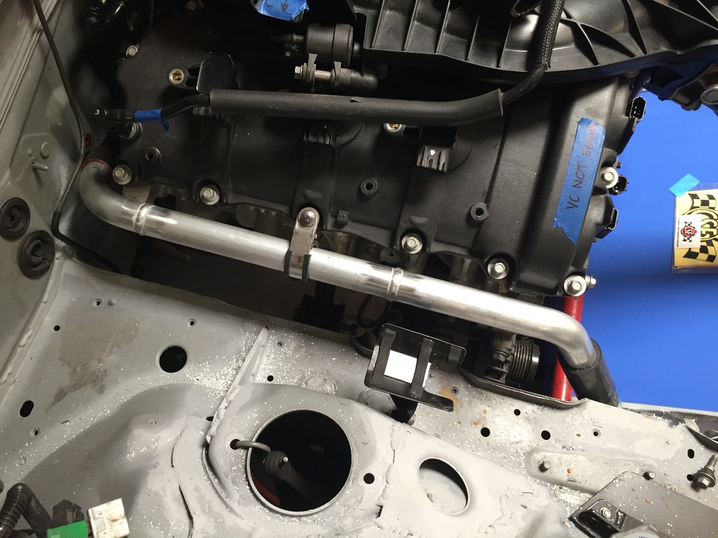
Need to join a 45� silicone coupler to that end, so that tube needed a bead on it. It's steel, so I welded a bead around the lip and smoothed that out with the grinder. Rather hard to see in this pic, but here is is mounted to the thermostat inlet on the back of the motor:
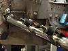
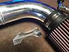
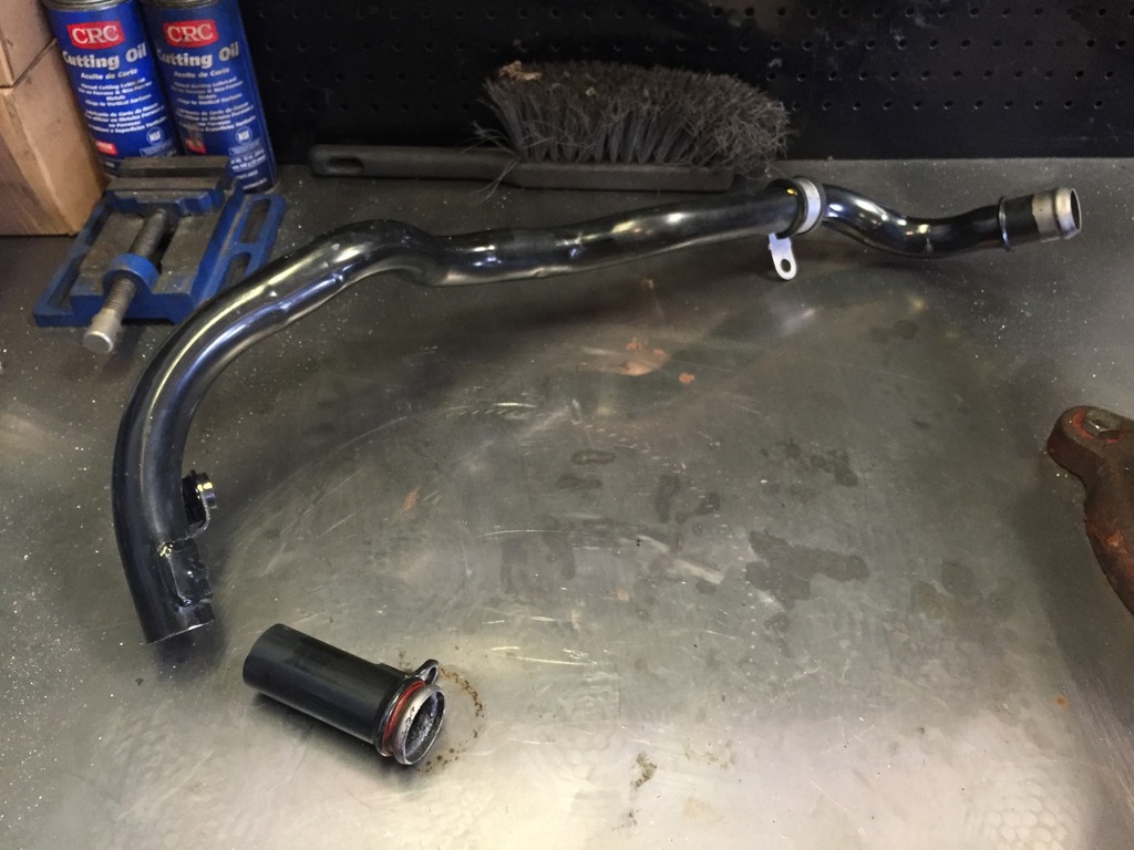
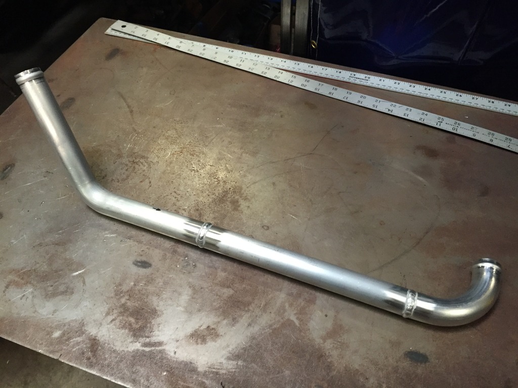
A couple mandrel-bent 1.25" aluminum bits and some of the straight tube stock I had laying around, melt some metal and shazam - we have a return line:

45� silicone coupler at the rear to join this line to the factory steel end, a straight silicone coupler from the aluminum line to the radiator outlet, and a big adel clamp to hold it nicely in place... and we have this:
The feed line from the engine to radiator has already been covered, that was pretty simple with just a couple 90� silicone bits and a straight joiner.
The return line back to the motor though needed a bit more attention. In the few LFX swaps that are out there so far, everyone's re-used a factory GM return line, but because I'm using an NC radiator which has the feed/return on the correct sides of the radiator to match the LFX (as oppose to NA/NB rads which are opposite), I could actually make use of the more direct and simplified routing that this makes possible. But, that means I need a new return line...
So, let's make one
The only bit I wanted to re-use from the factory line was the very end that meets the motor - for its specific o-ring and mounting tab there. So, I cut that bit off and discarded the rest:
Need to join a 45� silicone coupler to that end, so that tube needed a bead on it. It's steel, so I welded a bead around the lip and smoothed that out with the grinder. Rather hard to see in this pic, but here is is mounted to the thermostat inlet on the back of the motor:
A couple mandrel-bent 1.25" aluminum bits and some of the straight tube stock I had laying around, melt some metal and shazam - we have a return line:
45� silicone coupler at the rear to join this line to the factory steel end, a straight silicone coupler from the aluminum line to the radiator outlet, and a big adel clamp to hold it nicely in place... and we have this:
Reply
0
0
07-14-2016, 12:32 AM
#304
Supporting Vendor
Thread Starter
iTrader: (3)
Join Date: Jul 2006
Location: San Diego
Posts: 3,303
Total Cats: 1,216
I might have been accused once or twice that my solutions to all things involve either an angle grinder or a welder... but ideally both
If you think it's bad now, wait till I post the exhaust which I'm working on now
If you think it's bad now, wait till I post the exhaust which I'm working on now
Reply
0
0
 07-14-2016, 11:53 AM
#306
Junior Member

Join Date: Jul 2015
Location: grayson, ga
Posts: 295
Total Cats: 25
the nc radiator really simplifies the routing for the cooling, doesn't it. very nice. looking forward to the exhaust. these things are difficult to keep quiet (not so much for a racecar).
Last edited by portabull; 07-15-2016 at 10:15 AM.
Reply
0
0
07-14-2016, 01:42 PM
#307
Supporting Vendor
Thread Starter
iTrader: (3)
Join Date: Jul 2006
Location: San Diego
Posts: 3,303
Total Cats: 1,216
Fuel Lines
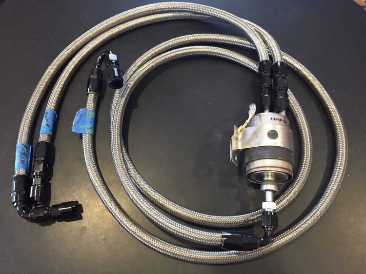
V8Roadsters supplies a very nice fuel line kit for the LFX. Very similar to their kits for V8 cars, it includes a Corvette filter, EFI fittings throughout, and assembled braided lines to replace all the factory lines in the car:
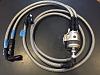
Dropped the fuel tank and took a look at things. The EFI fittings are very cool but they only work with the later-year fuel hard lines. Not a problem at the engine side because the LFX has the correct lines, but at the tank things need to be switched around since mine is an NA, so I need to swap to NB bits there.
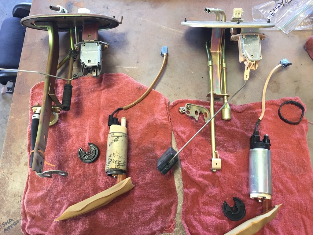
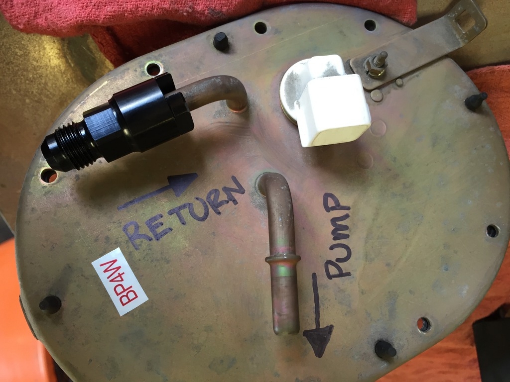
We had a junker NB sitting beside the shop, so I pulled the fuel pump assembly out of that. Had to do a little mix-and-matching of parts and as well as carrying over my Walbro 255lph pump to the NB fixture:
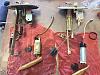
Using the NB's fuel pump fixture, the EFI fittings fit the hard lines perfectly:

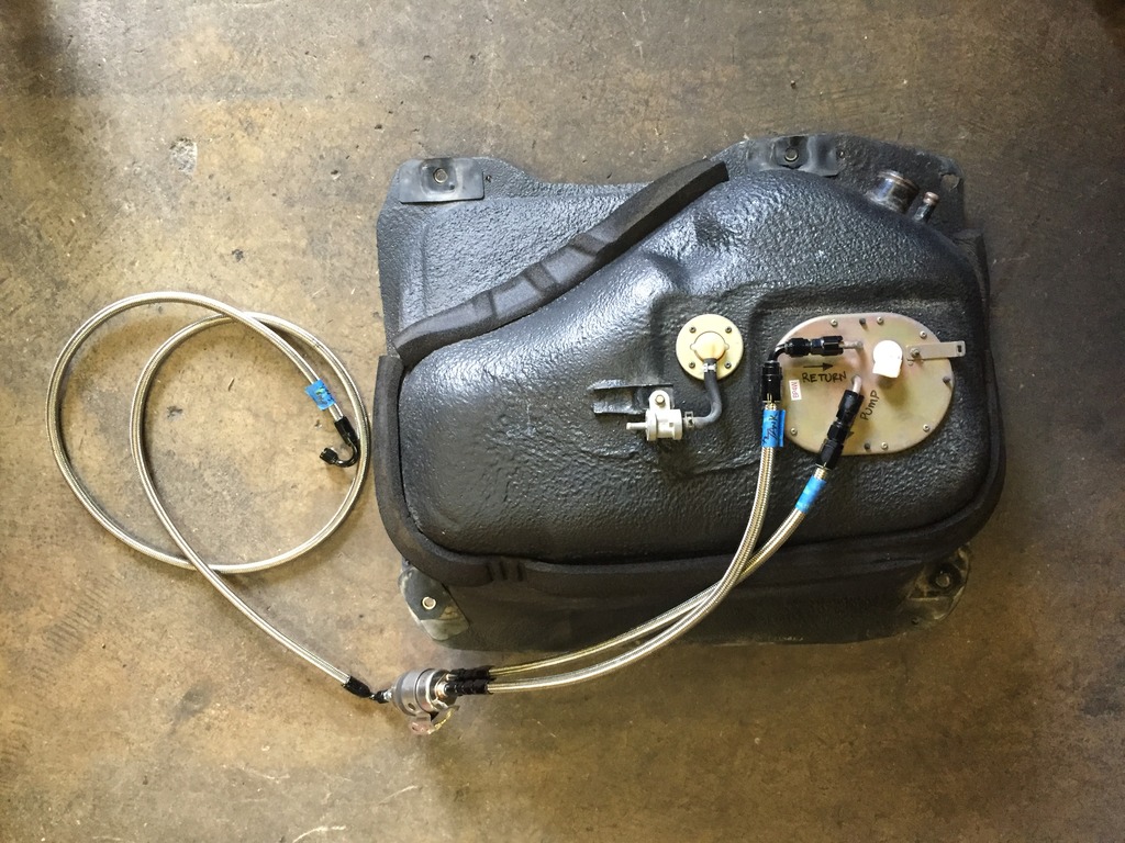
Lines attached, the tank is ready to go back in.. this pic is after lots of scrubbing of the fuel tank to get it clean:
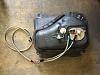
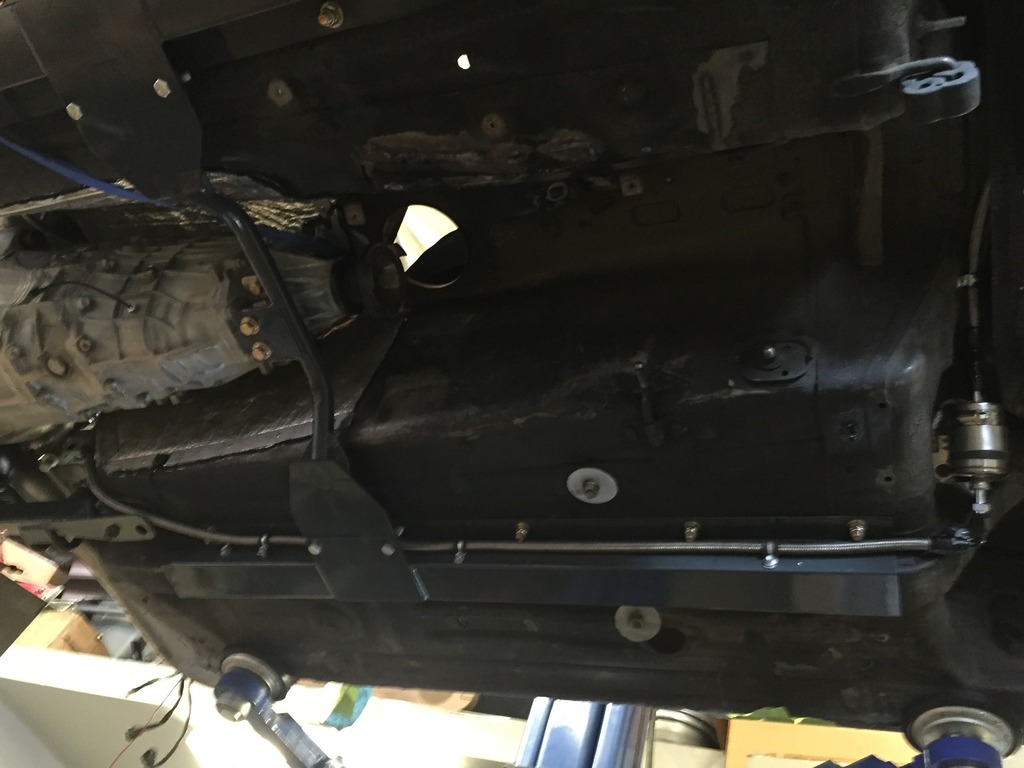
With the tank reinstalled, all that's left is to mount the filter and lines. Made a small bracket to hold the filter in place (don't have a pic of it), and the lines are routed along the inside of the frame rail. V8R says that they typically run the lines down the driver's side, but I found that running them down the passenger side I was able to shorten the line length by 12" (the easy route is to leave the line as-is and run down the driver's side):
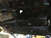
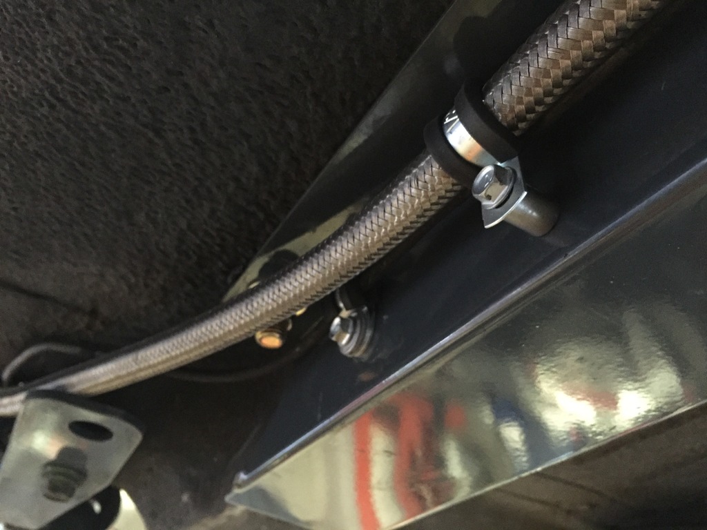
Close-up of the attachments for the fuel line - these adel clamps are included in V8R's kit. This is the front-most mount, I added the small stand-off to move the line away from the frame rail so it cleared the hard brake line that you can also see running behind it, which I ran at the same time:
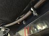
The end of the line curves up over the transmission and attaches to the LFX's fuel hard line and that's it, fuel system is done. Rear subframe and diff are back in the car too.
V8Roadsters supplies a very nice fuel line kit for the LFX. Very similar to their kits for V8 cars, it includes a Corvette filter, EFI fittings throughout, and assembled braided lines to replace all the factory lines in the car:
Dropped the fuel tank and took a look at things. The EFI fittings are very cool but they only work with the later-year fuel hard lines. Not a problem at the engine side because the LFX has the correct lines, but at the tank things need to be switched around since mine is an NA, so I need to swap to NB bits there.
We had a junker NB sitting beside the shop, so I pulled the fuel pump assembly out of that. Had to do a little mix-and-matching of parts and as well as carrying over my Walbro 255lph pump to the NB fixture:
Using the NB's fuel pump fixture, the EFI fittings fit the hard lines perfectly:
Lines attached, the tank is ready to go back in.. this pic is after lots of scrubbing of the fuel tank to get it clean:
With the tank reinstalled, all that's left is to mount the filter and lines. Made a small bracket to hold the filter in place (don't have a pic of it), and the lines are routed along the inside of the frame rail. V8R says that they typically run the lines down the driver's side, but I found that running them down the passenger side I was able to shorten the line length by 12" (the easy route is to leave the line as-is and run down the driver's side):
Close-up of the attachments for the fuel line - these adel clamps are included in V8R's kit. This is the front-most mount, I added the small stand-off to move the line away from the frame rail so it cleared the hard brake line that you can also see running behind it, which I ran at the same time:
The end of the line curves up over the transmission and attaches to the LFX's fuel hard line and that's it, fuel system is done. Rear subframe and diff are back in the car too.
Reply
0
0
07-23-2016, 05:02 AM
#308
Supporting Vendor
Thread Starter
iTrader: (3)
Join Date: Jul 2006
Location: San Diego
Posts: 3,303
Total Cats: 1,216
Exhaust: Part 1
Another area where I've got some fun ideas to carry out on this project.
It's been a while since the last update, and that is because I'm currently 71 hours in on this exhaust project (I told you this swap would have some very different requirements than a typical one!). I'll have it finished up by the end of this weekend, so I can finally start posting about it and will have finished pics in a couple days.
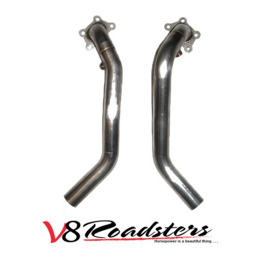
Before we get started, there's a BIG difference between the LFX and just about every other motor out there when it comes to the exhaust. The LFX collects the exhaust gasses from all three cylinders on each bank before they exit the head, so it all comes out in one single outlet on each side of the motor. People come by the shop to take a look at the car and ask "what are your plans for the headers" and the answer is... there aren't any headers! They are much more appropriately called Downpipes - as they are just a single tube on either side of the motor which drop down to the underside of the car much like a turbo system.

Now, the EASY route for doing your LFX exhaust:
V8Roadsters makes a tidy pair of downpipes that get you from the engine down to beside the bellhousing. Then it's a simple matter of taking the car to a good exhaust fab shop and get something made up to get things out to the back of the car with whichever combo of cats, resonators, and mufflers you want:
For this project, we're going a different route. Always thinking towards maximizing the competitive advantage where possible, this exhaust is going to go out to the sides of the car. Benefits should be three-fold; it will be overall lighter, there will be less heat by the transmission and differential, and it will allow for several aerodynamic ideas that I want to implement on this car.
Fun idea, but this presents plenty of challenges - the biggest one is there's no space for a side exhaust on an NA chassis; there isn't room for a big wide wheel and race tire to turn with an exhaust tube trying to share the wheel well space, and there is nowhere to put resonators or mufflers along the side of the car without them hanging WAY off the car - which would not be good for drag or ground clearance.
Some drastic surgery will be required.
Started with drilling holes and using the scope to figure out the internal layout of the rockers, then with a rough idea of how I want things to end up I began cutting, taking a little bit out at a time then investigating, adjusting, cutting more, etc.

Nearly all the cutting is done in the pic above, but the pinch weld is still there. After a lot of test fitting, I decided to get the fitment I wanted with everything I was going to have to take that out too. This meant more work - this is a critical area of the car in terms of chassis rigidity so anything I remove I have to rebuild a replacement for.
Below pic has the pinch weld cut out as well, and we�ve got the resonator mocked up roughly in position:

Now for the fun part. Need to rebuild the rocker in its new shape that accommodates the exhaust, and ideally we want the end result to be even stronger than the stock rocker.
The sections that will make up the main sides of the rockers:

The idea is to make the rocker concave instead of convex so there is room to nest the exhaust about half way up within the chassis. Something like this:

Holding that main piece up to the car it all looks pretty straightforward... I wish it was.
Creating the new rocker and the new lower section of the front wheel well took several pieces including a rather complicated 90� bend to transition between the two, plus a dozen or so additional pieces to rebuild the pinch weld inside the rocker so that all the chassis loads that normally transfer through that area can continue to do so, plus some additional gussets to make it all stronger than what was there before, To top it off it needed to be able to go together in a sequence that allowed me to weld each rocker piece to the ribs and gussets on their back side.

To put this all together took 5 yards of welding per side:

Cleaned up and primered:

Naturally, I weighed everything that got cut out and put in on this project. Thanks to a lot of careful figuring out, the new rocker matches the weight of what was removed within one pound.

At this point, I was lamenting the fact that this is a V engine and it was time to do this all over again on the driver's side.
Both sides are done now and mirror each other, and you can see why this car took 40 hours of work on the exhaust... before I actually began making the exhaust.
Exhaust is in progress now and will be done by the end of the weekend, part 2 coming soon!
Another area where I've got some fun ideas to carry out on this project.
It's been a while since the last update, and that is because I'm currently 71 hours in on this exhaust project (I told you this swap would have some very different requirements than a typical one!). I'll have it finished up by the end of this weekend, so I can finally start posting about it and will have finished pics in a couple days.
Before we get started, there's a BIG difference between the LFX and just about every other motor out there when it comes to the exhaust. The LFX collects the exhaust gasses from all three cylinders on each bank before they exit the head, so it all comes out in one single outlet on each side of the motor. People come by the shop to take a look at the car and ask "what are your plans for the headers" and the answer is... there aren't any headers! They are much more appropriately called Downpipes - as they are just a single tube on either side of the motor which drop down to the underside of the car much like a turbo system.
Now, the EASY route for doing your LFX exhaust:
V8Roadsters makes a tidy pair of downpipes that get you from the engine down to beside the bellhousing. Then it's a simple matter of taking the car to a good exhaust fab shop and get something made up to get things out to the back of the car with whichever combo of cats, resonators, and mufflers you want:
For this project, we're going a different route. Always thinking towards maximizing the competitive advantage where possible, this exhaust is going to go out to the sides of the car. Benefits should be three-fold; it will be overall lighter, there will be less heat by the transmission and differential, and it will allow for several aerodynamic ideas that I want to implement on this car.
Fun idea, but this presents plenty of challenges - the biggest one is there's no space for a side exhaust on an NA chassis; there isn't room for a big wide wheel and race tire to turn with an exhaust tube trying to share the wheel well space, and there is nowhere to put resonators or mufflers along the side of the car without them hanging WAY off the car - which would not be good for drag or ground clearance.
Some drastic surgery will be required.
Started with drilling holes and using the scope to figure out the internal layout of the rockers, then with a rough idea of how I want things to end up I began cutting, taking a little bit out at a time then investigating, adjusting, cutting more, etc.
Nearly all the cutting is done in the pic above, but the pinch weld is still there. After a lot of test fitting, I decided to get the fitment I wanted with everything I was going to have to take that out too. This meant more work - this is a critical area of the car in terms of chassis rigidity so anything I remove I have to rebuild a replacement for.
Below pic has the pinch weld cut out as well, and we�ve got the resonator mocked up roughly in position:
Now for the fun part. Need to rebuild the rocker in its new shape that accommodates the exhaust, and ideally we want the end result to be even stronger than the stock rocker.
The sections that will make up the main sides of the rockers:
The idea is to make the rocker concave instead of convex so there is room to nest the exhaust about half way up within the chassis. Something like this:
Holding that main piece up to the car it all looks pretty straightforward... I wish it was.
Creating the new rocker and the new lower section of the front wheel well took several pieces including a rather complicated 90� bend to transition between the two, plus a dozen or so additional pieces to rebuild the pinch weld inside the rocker so that all the chassis loads that normally transfer through that area can continue to do so, plus some additional gussets to make it all stronger than what was there before, To top it off it needed to be able to go together in a sequence that allowed me to weld each rocker piece to the ribs and gussets on their back side.
To put this all together took 5 yards of welding per side:
Cleaned up and primered:
Naturally, I weighed everything that got cut out and put in on this project. Thanks to a lot of careful figuring out, the new rocker matches the weight of what was removed within one pound.
At this point, I was lamenting the fact that this is a V engine and it was time to do this all over again on the driver's side.
Both sides are done now and mirror each other, and you can see why this car took 40 hours of work on the exhaust... before I actually began making the exhaust.
Exhaust is in progress now and will be done by the end of the weekend, part 2 coming soon!
Reply
7
7


 07-24-2016, 01:18 AM
#313
Supporting Vendor
Thread Starter
iTrader: (3)
Join Date: Jul 2006
Location: San Diego
Posts: 3,303
Total Cats: 1,216
It was an oven in the car with the downpipe running down the transmission tunnel and a sealed flat bottom under the car, so just about anything would be an improvement
Definitely planning to skin the rockers with heat reflective material, ordered several feet of the stuff. Also have plans for the side aero to channel air from the front wheel well down the side so there is constant flow over the exhaust pulling that heat away.
Definitely planning to skin the rockers with heat reflective material, ordered several feet of the stuff. Also have plans for the side aero to channel air from the front wheel well down the side so there is constant flow over the exhaust pulling that heat away.
Reply
0
0
 07-24-2016, 09:22 PM
#315
Supporting Vendor
Thread Starter
iTrader: (3)
Join Date: Jul 2006
Location: San Diego
Posts: 3,303
Total Cats: 1,216
The real no-clearance area was the back of the front wheel well, no way a decently wide tire could turn to full lock with a 2.5" tube sharing space back there, and I wanted to be sure to future proof and be sure there was enough room to run up to 15x11, so cutting into the tub was mandatory.
Reply
0
0
08-02-2016, 01:01 PM
#317
Supporting Vendor
Thread Starter
iTrader: (3)
Join Date: Jul 2006
Location: San Diego
Posts: 3,303
Total Cats: 1,216
Exhaust: Part 2 (yes there's actually an exhaust is this part)
Before starting on the exhaust itself there were a few more brackets to make for the rockers. The final plans for this area include a rather complex side skirt for aero purposes that will also channel air from the front wheel well down the side of the car to continuously pull the heat of the exhaust away. I'm not making those yet since they aren't a priority to get the car up and running, but I've got them about 90% figured out in my head and now was the time to make the mounting considerations for them:

Finally, on to the actual exhaust!
Materials ordered, not everything used is in this photo - ordered a few more parts later on. R2-D2 approved of the shiny stuff:

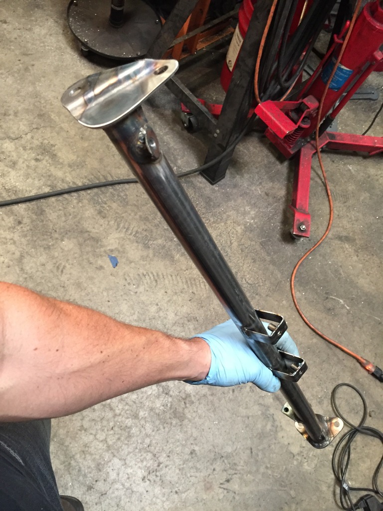
Began with the downtube. V8R has the CNC formed downtubes for traditional down-the-tunnel exhausts, and I almost got a set of those to start off from but it seemed a shame to cut those up and only use the top half of them so I decided to do it from scratch. I strongly recommend getting V8R's downtubes for anything but the most custom needs because forming the round tube to the rectangular shape of the engine flange within the 90� bend of the tube where it needs to be is not easy.
Sacrificing an exhaust flange, I made a jig for the shop press that would press the tube into the shape of the flange, it's crude but got the shape to 95% and then hammer-formed it the rest of the way:

Exhaust curves down quickly just like normal, but then makes a turn to head out towards the wheel well:

I was in the zone and didn't get many pics of the build process. Woops! I did snap a pic of cutting the exhaust exit tips:

Fast-forwarding quite a bit, here we've got one of the complete downtubes tack welded together, joints sealed up and backpurging gas being piped in, ready for final welding:

And with another fast-forward, full exhaust is finished! Measuring the total length of everything here and comparing to the length needed for an out-the-back exhaust, this side exit exhaust saves me 50 inches of length, approximately 10 lbs:

The downtubes carry the exhaust from the engine down to the bend at the rocker, with a V-band flange pointing straight down the car from there so that the rest of the exhaust is modular. This allows me to easily make different straight sections if I want to test alternate resonators or mufflers.
You'll also see two cats in the pic above (Wait, cats on a race car? Why??) I wanted to be sure I could fit cats in the system, and since those would be the largest thing I might be trying to fit there I made those first to be sure they fit, and will make a pair of straight cat deletes later that can be swapped in. Cats do a good job of reducing volume, and V8R reports this is a loud motor when you're on the GO pedal so I'll likely also use the cats as an option when I need to bring the volume level down at certain tracks, etc.
Installed, the exhaust tucks into the rocker nicely:

Shot from below shows the full route well:

From the perspective we'll be seeing it from more often, I'm quite happy with how it's tucked into the car. The exhaust won't ever be quite as exposed as it is here, since the side skirt will envelope it to direct air, but it will remain like this until it's up and running:

Speaking of weight, the full 3" lightweight exhaust that came off this car for the 4 cylinder and turbo was 26 lbs including the downpipe but NOT including the cast iron manifold which was easily 10+ lbs. That exhaust had no cat and no muffler to save weight.
This new exhaust totals 30 lbs all-in, including the cats and everything up to the motor, so somehow in changing to a V6 which has to double everything and adding resonators and even with cats I've saved weight over the uber-minimalist turbo exhaust that came off the car. I'll take that!
Before starting on the exhaust itself there were a few more brackets to make for the rockers. The final plans for this area include a rather complex side skirt for aero purposes that will also channel air from the front wheel well down the side of the car to continuously pull the heat of the exhaust away. I'm not making those yet since they aren't a priority to get the car up and running, but I've got them about 90% figured out in my head and now was the time to make the mounting considerations for them:
Finally, on to the actual exhaust!
Materials ordered, not everything used is in this photo - ordered a few more parts later on. R2-D2 approved of the shiny stuff:
Began with the downtube. V8R has the CNC formed downtubes for traditional down-the-tunnel exhausts, and I almost got a set of those to start off from but it seemed a shame to cut those up and only use the top half of them so I decided to do it from scratch. I strongly recommend getting V8R's downtubes for anything but the most custom needs because forming the round tube to the rectangular shape of the engine flange within the 90� bend of the tube where it needs to be is not easy.
Sacrificing an exhaust flange, I made a jig for the shop press that would press the tube into the shape of the flange, it's crude but got the shape to 95% and then hammer-formed it the rest of the way:
Exhaust curves down quickly just like normal, but then makes a turn to head out towards the wheel well:
I was in the zone and didn't get many pics of the build process. Woops! I did snap a pic of cutting the exhaust exit tips:
Fast-forwarding quite a bit, here we've got one of the complete downtubes tack welded together, joints sealed up and backpurging gas being piped in, ready for final welding:
And with another fast-forward, full exhaust is finished! Measuring the total length of everything here and comparing to the length needed for an out-the-back exhaust, this side exit exhaust saves me 50 inches of length, approximately 10 lbs:
The downtubes carry the exhaust from the engine down to the bend at the rocker, with a V-band flange pointing straight down the car from there so that the rest of the exhaust is modular. This allows me to easily make different straight sections if I want to test alternate resonators or mufflers.
You'll also see two cats in the pic above (Wait, cats on a race car? Why??) I wanted to be sure I could fit cats in the system, and since those would be the largest thing I might be trying to fit there I made those first to be sure they fit, and will make a pair of straight cat deletes later that can be swapped in. Cats do a good job of reducing volume, and V8R reports this is a loud motor when you're on the GO pedal so I'll likely also use the cats as an option when I need to bring the volume level down at certain tracks, etc.
Installed, the exhaust tucks into the rocker nicely:
Shot from below shows the full route well:
From the perspective we'll be seeing it from more often, I'm quite happy with how it's tucked into the car. The exhaust won't ever be quite as exposed as it is here, since the side skirt will envelope it to direct air, but it will remain like this until it's up and running:
Speaking of weight, the full 3" lightweight exhaust that came off this car for the 4 cylinder and turbo was 26 lbs including the downpipe but NOT including the cast iron manifold which was easily 10+ lbs. That exhaust had no cat and no muffler to save weight.
This new exhaust totals 30 lbs all-in, including the cats and everything up to the motor, so somehow in changing to a V6 which has to double everything and adding resonators and even with cats I've saved weight over the uber-minimalist turbo exhaust that came off the car. I'll take that!
Reply
8
8
08-02-2016, 01:22 PM
#318
Elite Member

iTrader: (9)
Join Date: Jun 2006
Location: Chesterfield, NJ
Posts: 6,892
Total Cats: 399
Once again, that's so slick. Nice job.
I wonder if this will sound like an angry geo metro as it passes, with only 3 cyl's of noise pointing at you. It will be mean inside a garage or from either end.
I wonder if this will sound like an angry geo metro as it passes, with only 3 cyl's of noise pointing at you. It will be mean inside a garage or from either end.
Reply
0
0


