
Miata LFX Swap (Singular Motorsports & Good-Win Racing)
 02-02-2017, 08:48 PM
#461
SADFab Destructive Testing Engineer


iTrader: (5)
Join Date: Apr 2014
Location: Beaverton, USA
Posts: 18,642
Total Cats: 1,866
When I looked in the DataLink software it let me change the input to a 3 wire sensor. But it wouldnt let me select 100psi 3 wire. Kind of weird.
There is a user calibration table though.
There is a user calibration table though.

Reply
 0
0

0
02-02-2017, 11:36 PM
#462
Supporting Vendor

Thread Starter
iTrader: (3)

Join Date: Jul 2006
Location: San Diego
Posts: 3,303
Total Cats: 1,216
Ok, looking at the wiring plans I've been working on I think there's a good solution here that actually simplifies the wiring too.
The USM has the following terminals for each sensor: Shield / Ground / Signal / +5V / +12V, so it's ready to go for a 3-wire OP sensor and the USM is going in the engine bay so this won't add to the number of wires going through the firewall. This bumps one of the originally planned 4 sensors out of the USM, but that's OK because the diff temp sensor is in the back of the car, might as well just wire that straight to one of the dash harnesses sensor inputs and save having to send those wires forward through the firewall anyways.
Searching around I'm seeing various opinions on if it might work without the factory sensor. I'd rather not have to go back in and drill/tap for a sensor, add wiring to an already finished harness, etc. if I find out the ECU insists on seeing that sensor.
The USM has the following terminals for each sensor: Shield / Ground / Signal / +5V / +12V, so it's ready to go for a 3-wire OP sensor and the USM is going in the engine bay so this won't add to the number of wires going through the firewall. This bumps one of the originally planned 4 sensors out of the USM, but that's OK because the diff temp sensor is in the back of the car, might as well just wire that straight to one of the dash harnesses sensor inputs and save having to send those wires forward through the firewall anyways.
The question is begged - Any reason to run the stock sensor at all? Pretty sure you could mute the MIL in hptuners - and the oil controlled cams should be closed loop not watching the oil pressure for data. I can't seem to find it, but I think the stock oil pressure is 0-120psi (though my math on the PID I monitor indicates 0-150psi). https://www.alibaba.com/product-deta...424792154.html puts it at 0.9mpa which is 130psi.

Reply
0
0
 02-03-2017, 07:59 AM
#464

The CMP actuator solenoid valve (7) is controlled by the ECM. The crankshaft position (CKP) sensor and the CMP sensors are used to monitor changes in camshaft positions. The ECM uses the following information in order to calculate the desired camshaft positions:
- Engine coolant temperature
- Calculated engine oil temperature (EOT)
- Mass air flow (MAF)
- Throttle position (TP)
- Vehicle speed
- Volumetric efficiency
Reply
0
0
02-05-2017, 01:42 AM
#465
Supporting Vendor
Thread Starter
iTrader: (3)
Join Date: Jul 2006
Location: San Diego
Posts: 3,303
Total Cats: 1,216
Changing topics for a moment from the electronics to what I was able to finish up today. With the last of the fittings arriving yesterday, today I completed everything that carries fluids in the front end. Now that I've finished that up and know for certain how it's all going together I can finally cover each system in its own post.
Power Steering
We begin with V8R's power steering kit. Included are fittings/lines to replace the hard lines that run along the rack itself with steel braided lines as well as fittings and a high pressure braided line for pump to rack. The kit leaves it to the user to sort out the low pressures lines (usually rubber) and reservoir (I've heard the factory Miata unit can be used), so that blue 180� hose barb fitting is supplied for the exit from the rack.
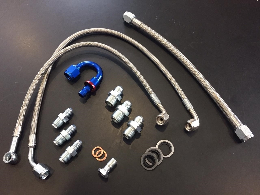
I used everything above except the hose barb fitting because this car will use braided lines throughout.
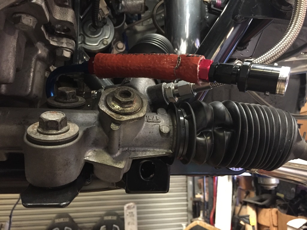
Removed the old lines from the rack and spent a good deal of time cleaning the rack up. The power rack I got from a donor car seemed to have been competing for the coveted title of thickest layer of grime, but it’s shiny now.
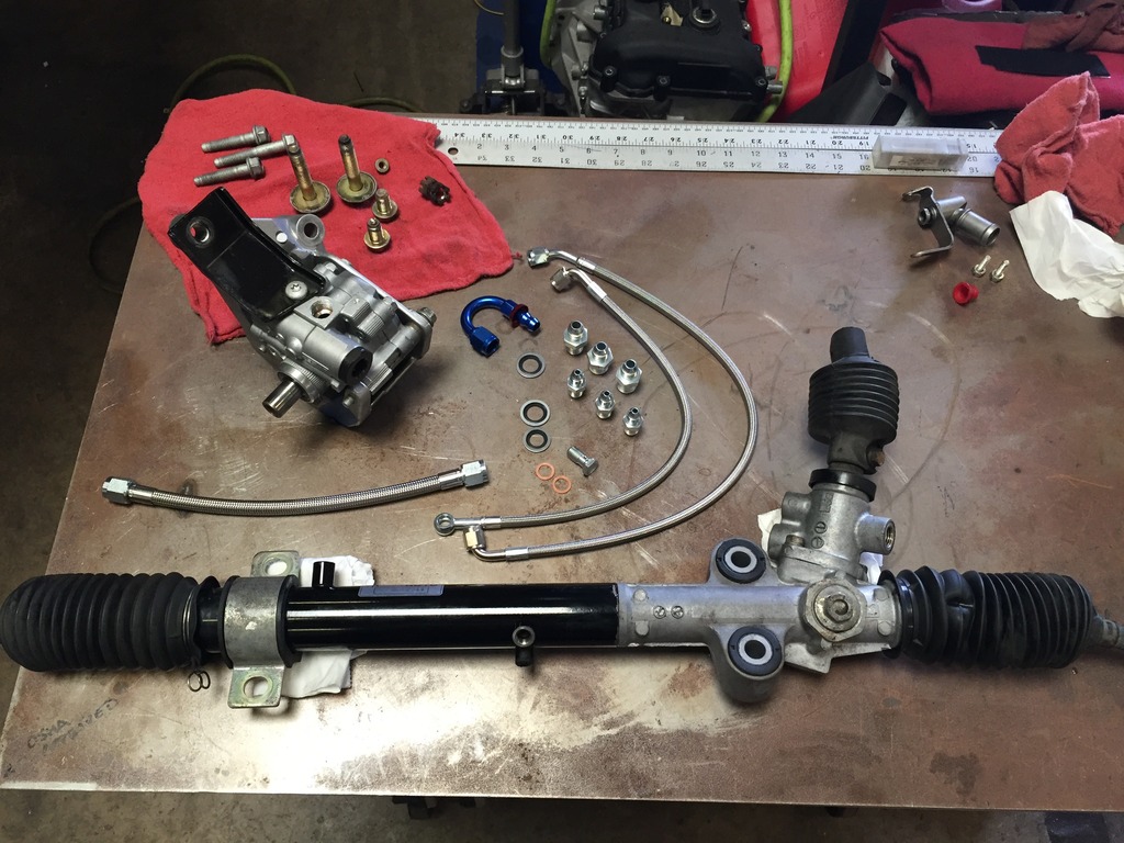
Here’s the rack with the V8R lines added. Also pictured is the early version of the rack to cooler line I made which I later added the in-line dry break to:
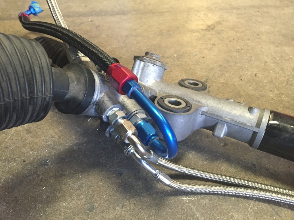
Closeup shot. This bunch sit close to the pan once installed so best to leave them loose and adjust the angles once both the engine and rack are in place:
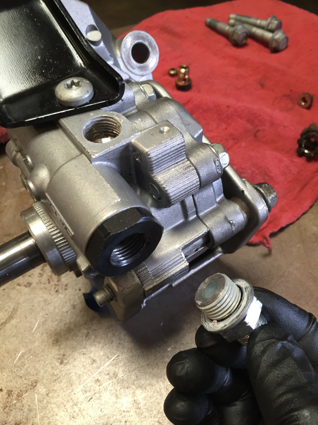
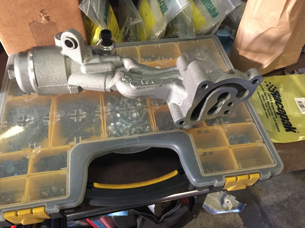
Pic of the power steering pump. The black threaded outlet goes to the rack which V8R supplies a fitting for (that’s what I’m holding in the photo). The port above that is the inlet from the reservoir. That port has a barbed end for a rubber hose in the stock GM form, but as seen in this pic I removed that and drilled/tapped the hole to adapt it to an AN fitting:
A note on the power steering pump pulley -
To remove the pump from the engine you must remove the pulley from the pump first. This took us a combination of parts from a rather comprehensive pulley puller kit, something most home garages may not be equipped with. Reinstallation of the pulley is equally difficult. I’d recommend leaving the pump on the engine unless you absolutely have to remove it. However, there is a complication if you’re going to add an engine oil cooler; to remove the factory oil filter housing you have to remove the steering pump first because the filter housing’s bolts are too long and can’t be backed all the way out with the pump in place. For shame, GM! Later, when I installed the Keisler oil reroute plate in place of the stock filter housing I swapped two of the factory bolts out for shorter ones and now the plate can be installed/removed with the steering pump in place. At any rate, if you need to remove the filter housing you’ll have to take the pump off at least once.
Now back to our regularly scheduled programming…
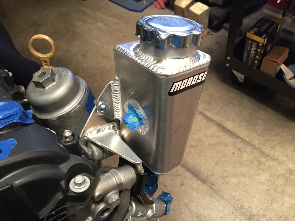
The next piece to the puzzle was the steering fluid reservoir. The reservoir needs to sit higher than the pump as it is a gravity feed. The pump’s position on the motor is high enough that there was a good bit of head scratching and lots of looking around at various reservoir options/shapes/etc. to figure out what to do. The solution I came up with uses a Moroso reservoir mounted directly to the top of the pump NASCAR style. This eliminated the need for a hose and guarantees good flow from the reservoir to pump. This reservoir is actually intended for power steering so it has the appropriate internal baffles.
I don’t have a pic of the reservoir by itself but you’ll see it in following pics. The reservoir had an AN bung in the bottom for the drain so with a couple fittings the pump was set up for the direct-mount:
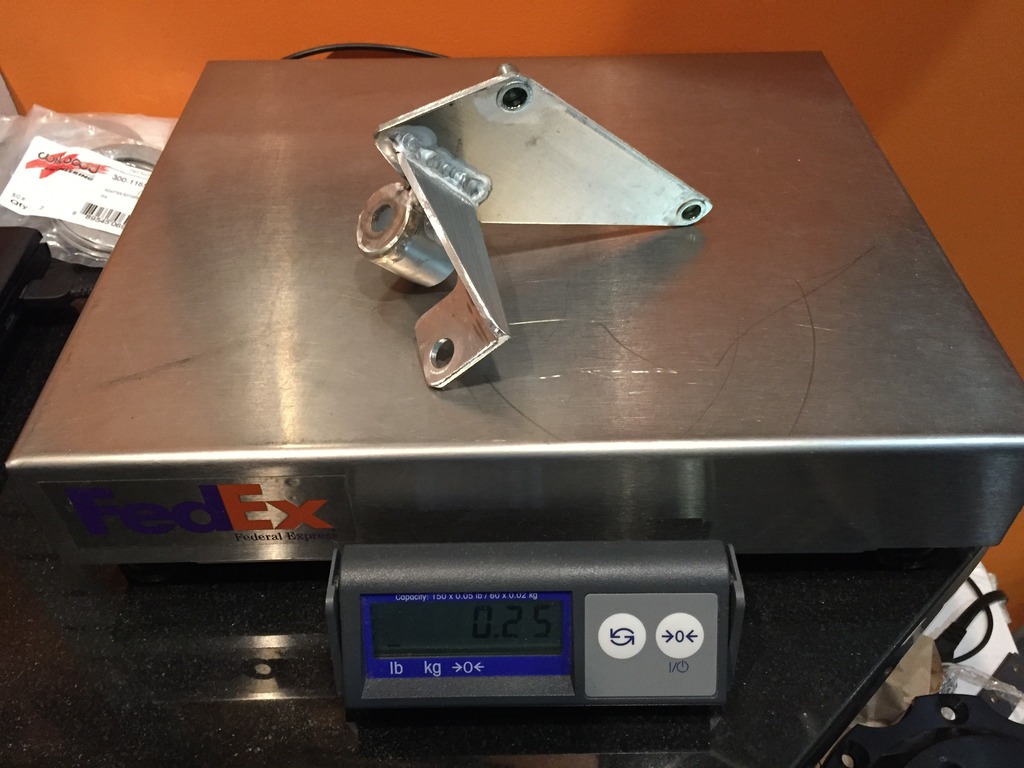
To hold the reservoir in place requires a bracket Always up for challenging myself, I decided to make it from aluminum. Here is an in-progress pic about 80% of the way done, just before tack welding the two halves I made together:
It turned out to be a funky looking little thing but it’s nice and light, piggy backs on existing factory bolts, and does just what’s needed:
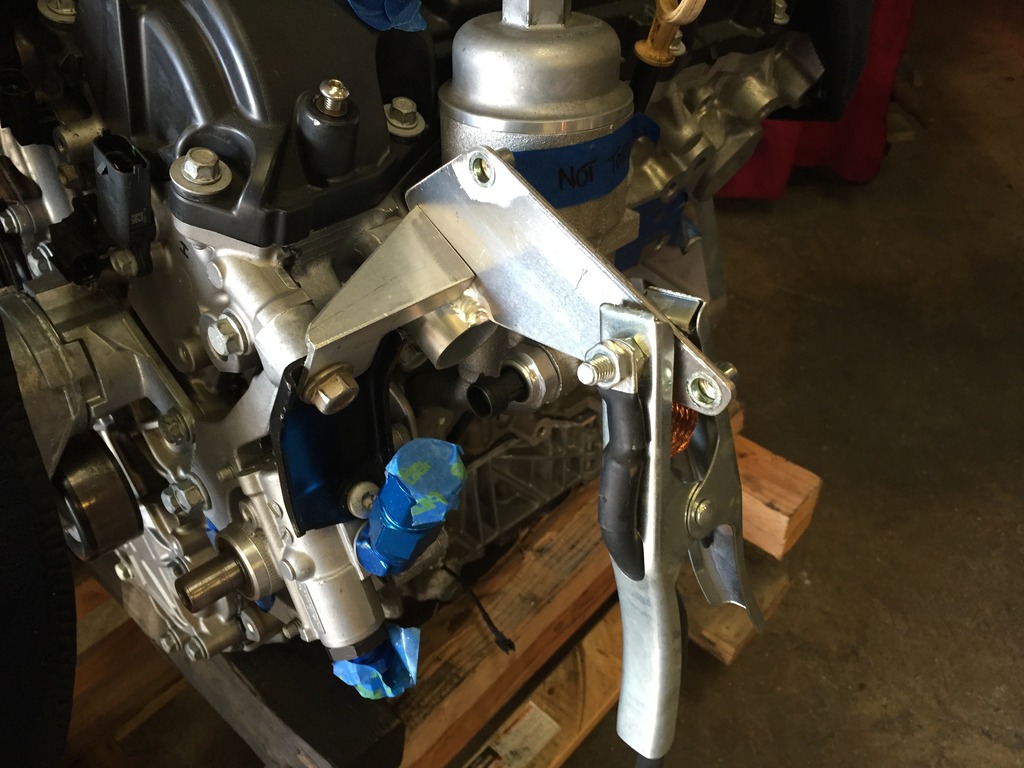
Here it’s mounted up with the reservoir. Note the factory oil filter housing is still in place behind there, but that is removed later for the oil cooler:
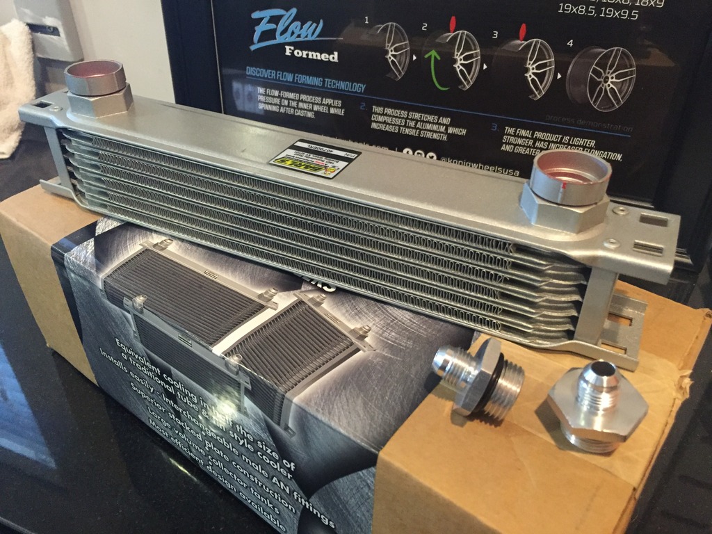
The final piece in the power steering system is the cooler. Most cars doing any sort of performance driving will need one, you don’t want this system overheating and spraying flammable fluid around the engine bay. If you’re doing a more standard street setup with rubber lines there are lots of affordable cooler options with barbed ends built in. For this car I chose Earl’s 40700 cooler, which is a 13”x2”x2” unit, with -6AN ends. I erred on the small side to keep weight down but Earl’s stuff has efficient cores so I think it will do the trick. I’ll be monitoring fluid temp so I’ll know if it is sized well or needs to be upgraded:
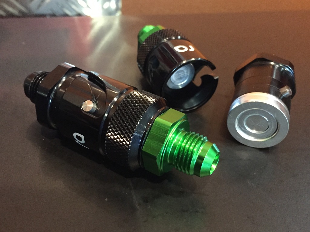
Back when I was making the removable nose I made the brackets to hold the cooler in place. With the cooler, pump and reservoir all settled in all that’s left is to connect the dots with the lines. Embracing the idea of having the whole front nose section quickly removable, I picked up a pair of Radium -6AN dry break fittings for the power steering lines:
Long line below is cooler to reservoir, with the dry break junction fixed to the reservoir side. The short one is half of the rack to cooler line:
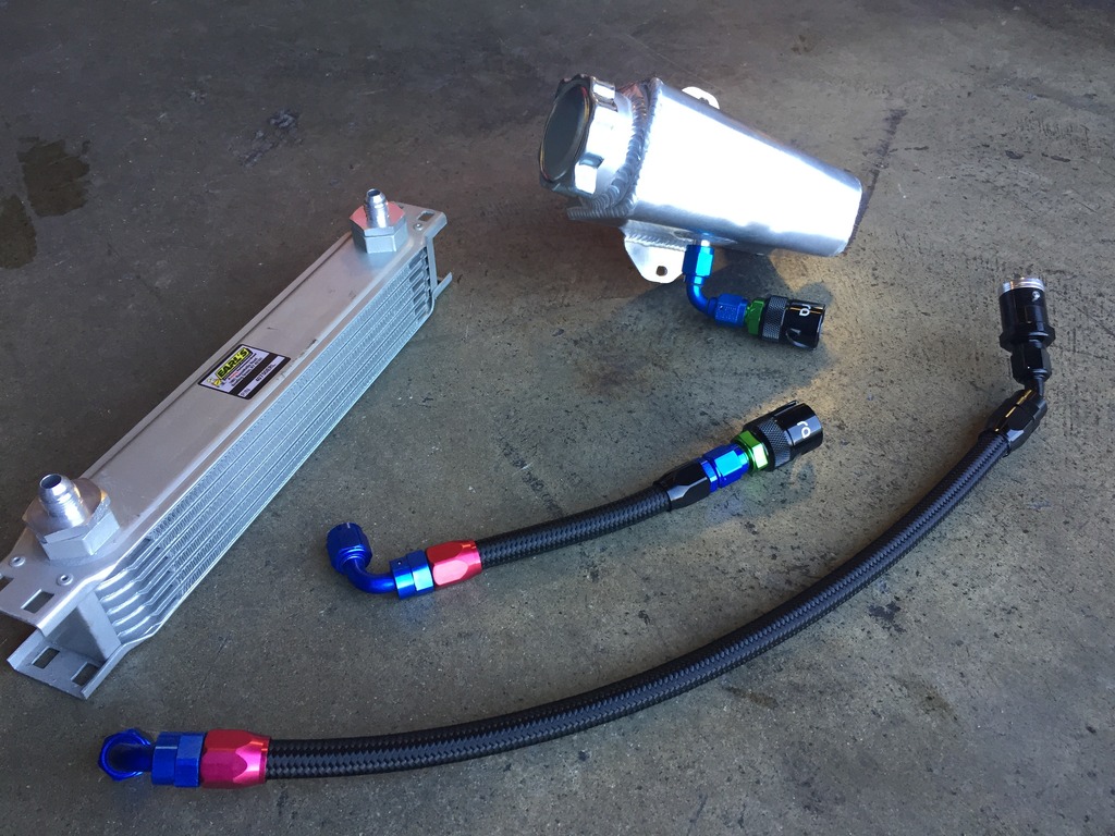
Here’s the other half of that lower line, I had already fixed it to the rack and didn’t want to remove it for the last pic. This section has a fire sleeve since it's in the vicinity of the exhaust:
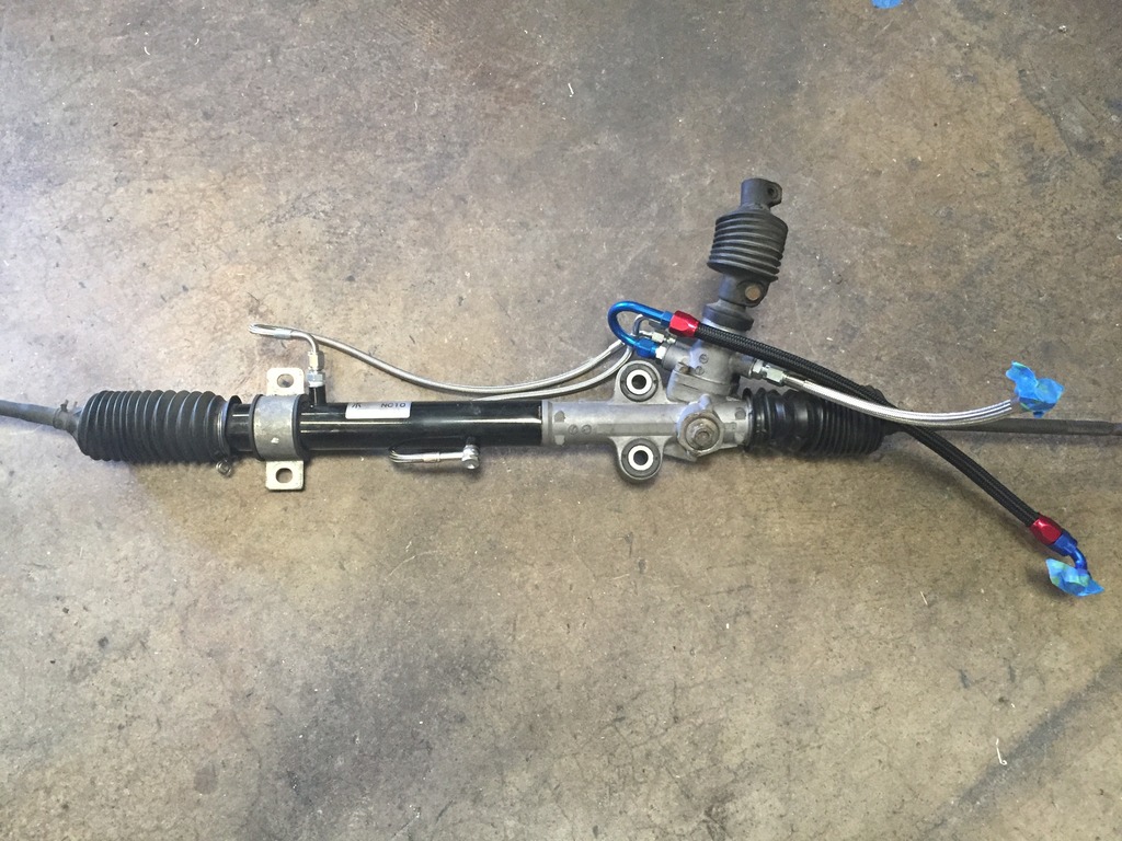
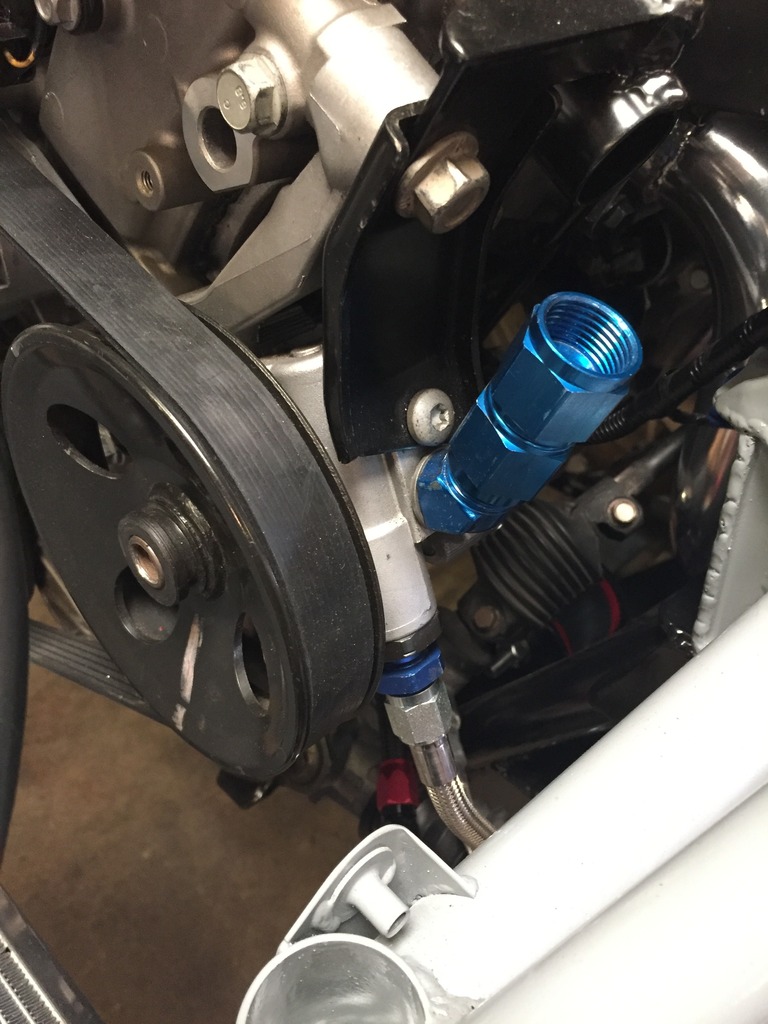
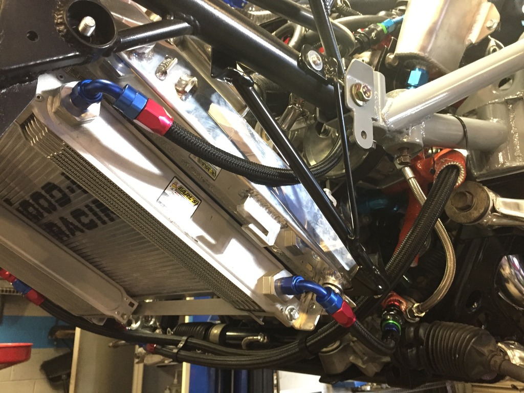
Final setup installed:
That concludes the power steering setup. Tomorrow I'll write up the oil cooler system.
Power Steering
We begin with V8R's power steering kit. Included are fittings/lines to replace the hard lines that run along the rack itself with steel braided lines as well as fittings and a high pressure braided line for pump to rack. The kit leaves it to the user to sort out the low pressures lines (usually rubber) and reservoir (I've heard the factory Miata unit can be used), so that blue 180� hose barb fitting is supplied for the exit from the rack.
I used everything above except the hose barb fitting because this car will use braided lines throughout.
Removed the old lines from the rack and spent a good deal of time cleaning the rack up. The power rack I got from a donor car seemed to have been competing for the coveted title of thickest layer of grime, but it’s shiny now.
Here’s the rack with the V8R lines added. Also pictured is the early version of the rack to cooler line I made which I later added the in-line dry break to:
Closeup shot. This bunch sit close to the pan once installed so best to leave them loose and adjust the angles once both the engine and rack are in place:
Pic of the power steering pump. The black threaded outlet goes to the rack which V8R supplies a fitting for (that’s what I’m holding in the photo). The port above that is the inlet from the reservoir. That port has a barbed end for a rubber hose in the stock GM form, but as seen in this pic I removed that and drilled/tapped the hole to adapt it to an AN fitting:
A note on the power steering pump pulley -
To remove the pump from the engine you must remove the pulley from the pump first. This took us a combination of parts from a rather comprehensive pulley puller kit, something most home garages may not be equipped with. Reinstallation of the pulley is equally difficult. I’d recommend leaving the pump on the engine unless you absolutely have to remove it. However, there is a complication if you’re going to add an engine oil cooler; to remove the factory oil filter housing you have to remove the steering pump first because the filter housing’s bolts are too long and can’t be backed all the way out with the pump in place. For shame, GM! Later, when I installed the Keisler oil reroute plate in place of the stock filter housing I swapped two of the factory bolts out for shorter ones and now the plate can be installed/removed with the steering pump in place. At any rate, if you need to remove the filter housing you’ll have to take the pump off at least once.
Now back to our regularly scheduled programming…
The next piece to the puzzle was the steering fluid reservoir. The reservoir needs to sit higher than the pump as it is a gravity feed. The pump’s position on the motor is high enough that there was a good bit of head scratching and lots of looking around at various reservoir options/shapes/etc. to figure out what to do. The solution I came up with uses a Moroso reservoir mounted directly to the top of the pump NASCAR style. This eliminated the need for a hose and guarantees good flow from the reservoir to pump. This reservoir is actually intended for power steering so it has the appropriate internal baffles.
I don’t have a pic of the reservoir by itself but you’ll see it in following pics. The reservoir had an AN bung in the bottom for the drain so with a couple fittings the pump was set up for the direct-mount:
To hold the reservoir in place requires a bracket
Always up for challenging myself, I decided to make it from aluminum. Here is an in-progress pic about 80% of the way done, just before tack welding the two halves I made together:It turned out to be a funky looking little thing but it’s nice and light, piggy backs on existing factory bolts, and does just what’s needed:
Here it’s mounted up with the reservoir. Note the factory oil filter housing is still in place behind there, but that is removed later for the oil cooler:
The final piece in the power steering system is the cooler. Most cars doing any sort of performance driving will need one, you don’t want this system overheating and spraying flammable fluid around the engine bay. If you’re doing a more standard street setup with rubber lines there are lots of affordable cooler options with barbed ends built in. For this car I chose Earl’s 40700 cooler, which is a 13”x2”x2” unit, with -6AN ends. I erred on the small side to keep weight down but Earl’s stuff has efficient cores so I think it will do the trick. I’ll be monitoring fluid temp so I’ll know if it is sized well or needs to be upgraded:
Back when I was making the removable nose I made the brackets to hold the cooler in place. With the cooler, pump and reservoir all settled in all that’s left is to connect the dots with the lines. Embracing the idea of having the whole front nose section quickly removable, I picked up a pair of Radium -6AN dry break fittings for the power steering lines:
Long line below is cooler to reservoir, with the dry break junction fixed to the reservoir side. The short one is half of the rack to cooler line:
Here’s the other half of that lower line, I had already fixed it to the rack and didn’t want to remove it for the last pic. This section has a fire sleeve since it's in the vicinity of the exhaust:
Final setup installed:
That concludes the power steering setup. Tomorrow I'll write up the oil cooler system.
Reply
2
2


 02-05-2017, 11:38 AM
#469
SADFab Destructive Testing Engineer
iTrader: (5)
Join Date: Apr 2014
Location: Beaverton, USA
Posts: 18,642
Total Cats: 1,866
Hey Ryan I was digging around the OBD-2 protocols, and the one used by Racepak (2008 and newer) is just a CAN signal. So there is a chance that you can use the user defined ECU settings and define your own configs. This is what I ended up having to do with the megasquirt after they said they only supported the default broadcasts.
Reply
0
0
 02-05-2017, 12:29 PM
#471
SAE J1979 defines a lot of the higher level specs of OBDII (that don't depend on whether it uses 15765 CAN mode), and PIDs are all request/response rather than broadcast. Very different than setting up MS3 channels; does RacePak even support that for custom channels?
Reply
0
0
02-05-2017, 12:32 PM
#472
SADFab Destructive Testing Engineer
iTrader: (5)
Join Date: Apr 2014
Location: Beaverton, USA
Posts: 18,642
Total Cats: 1,866
I'm not sure. I was told they would send me documentation on the user defined ECU channels and it never arrived. I blundered my way through it. It only supports 2008 never vehicles though, so at least the electrical signal is the same as CAN.
Reply
0
0
02-06-2017, 11:23 AM
#473
Supporting Vendor
Thread Starter
iTrader: (3)
Join Date: Jul 2006
Location: San Diego
Posts: 3,303
Total Cats: 1,216
Hey Ryan I was digging around the OBD-2 protocols, and the one used by Racepak (2008 and newer) is just a CAN signal. So there is a chance that you can use the user defined ECU settings and define your own configs. This is what I ended up having to do with the megasquirt after they said they only supported the default broadcasts.
Reply
0
0
02-06-2017, 11:25 AM
#474
Supporting Vendor
Thread Starter
iTrader: (3)
Join Date: Jul 2006
Location: San Diego
Posts: 3,303
Total Cats: 1,216
Oil Cooling
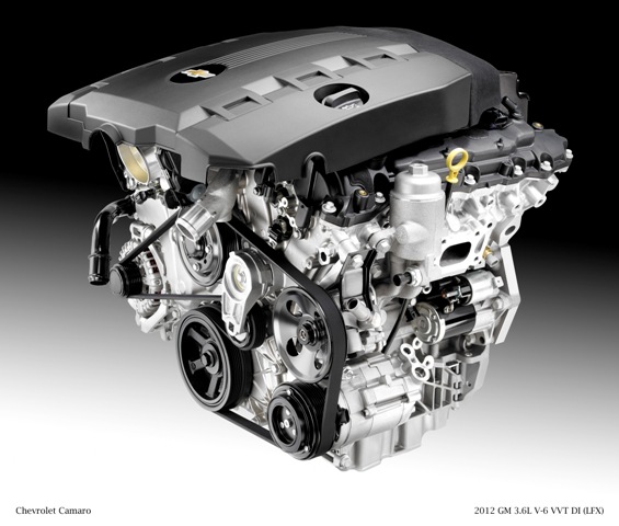
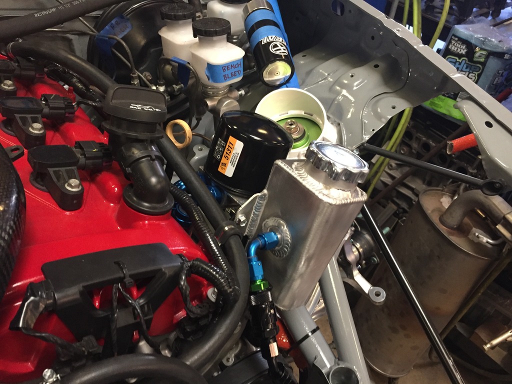
First the hurdle. The factory oil filter setup is a cast aluminum housing that bolts to the left side of the block and extends up to hold the filter canister up near the fill cap. You can see the housing just forwards of the dipstick:
To run an oil cooler we need an inlet and outlet for the lines, but a traditional sandwich plate won’t work here because of the unique shape of the ports where the block and housing meet:
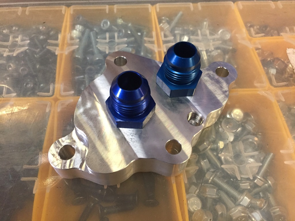
Conveniently, Keisler Automation has been working on a solution. Here is their oil reroute plate:
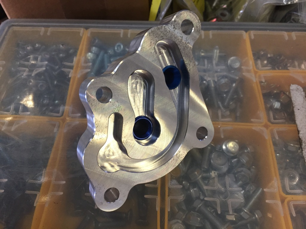
This plate has a pair of M16x1.5 ports to which I added the metric to -10AN adapters. It also has an ⅛ NPT port for a sensor, but I found its location to be too cramped beside the larger fittings (and the GM oil pressure sensor is M14x1.5 anyways) so after this pic was taken I plugged that port and put the sensor in the remote filter plate:
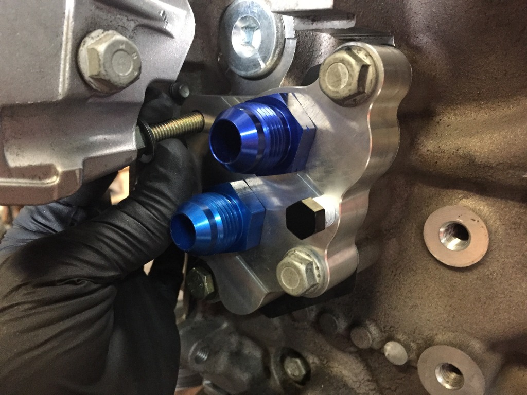
As I mentioned in the power steering post, the factory oil filter housing can’t be removed without taking the steering pump off because the factory bolts are too long. There’s no getting around this the first time, but when installing the Keisler plate I switched the two forward bolts to shorter ones - this makes it possible to remove/install the plate with the steering pump in place. I forgot to write it down but I believe I used M8x1.25x25mm:
With the in/out for the hoses sorted all that’s left is a remote filter and a cooler. For the remote filter adapter it was important to me for it to be mounted to the engine so that removing the engine requires as little disassembly as possible. I played with a few locations and came up with doubling up the filter adapter on the same bracket that holds the power steering reservoir. Here’s the filter adapter mounted up to that bracket (now powdercoated black) with the steering reservoir not yet mounted:
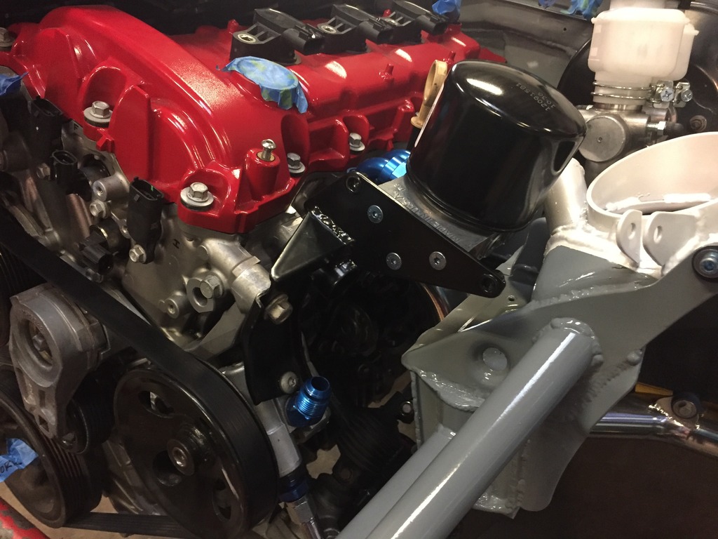
Here it is with the steering reservoir in place. The filter location ended up mimicking the factory location a bit. Oil changes will be a breeze:
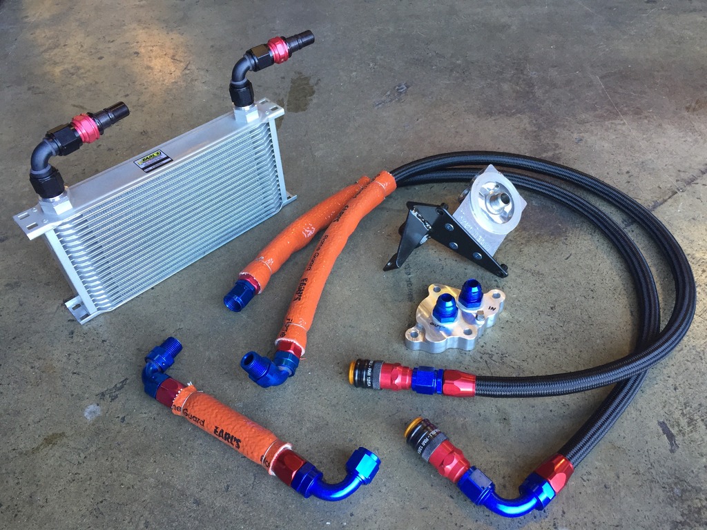
Now for lines and the cooler. For the cooler I chose another Earl’s unit - same depth and length as the power steering unit but taller; 19 rows instead of 7.
Just as I did with the power steering system, in order to make the entire nose assembly quickly removable I chose to add dry breaks here. Staubli -10AN units for the oil lines:
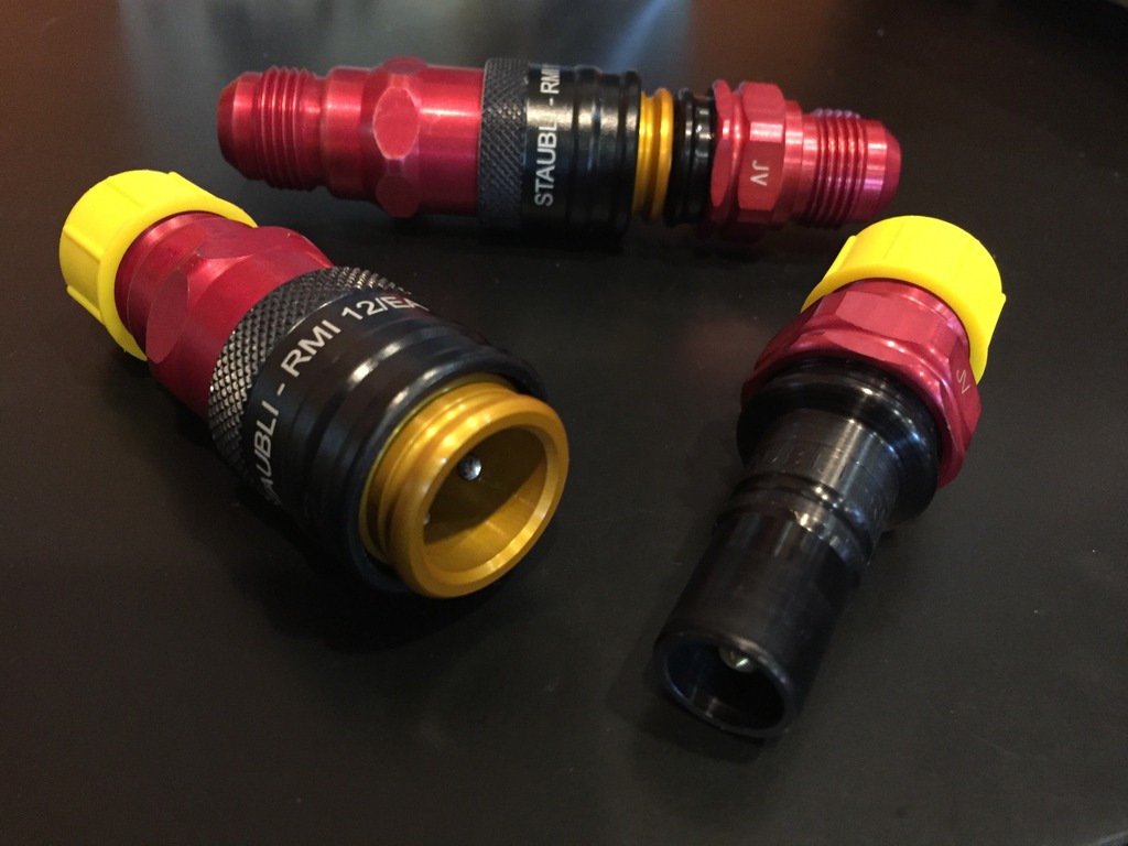
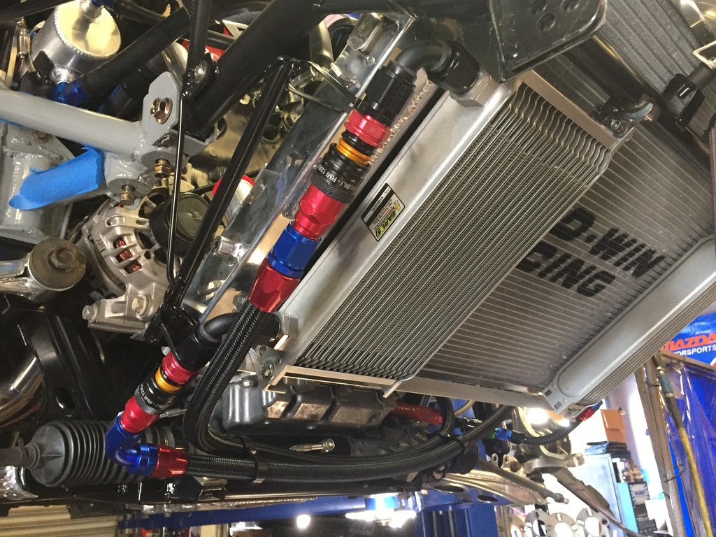
Here’s the full system just before final install. I fit the dry breaks directly to the cooler so that the feed and return lines remained one line each rather than being split into two. Fire sleeves on the portion of the lines that are anywhere near the exhaust. The short line is oil plate outlet to remote filter inlet and the long lines of course go to the cooler:
Installed:
First the hurdle. The factory oil filter setup is a cast aluminum housing that bolts to the left side of the block and extends up to hold the filter canister up near the fill cap. You can see the housing just forwards of the dipstick:
To run an oil cooler we need an inlet and outlet for the lines, but a traditional sandwich plate won’t work here because of the unique shape of the ports where the block and housing meet:
Conveniently, Keisler Automation has been working on a solution. Here is their oil reroute plate:
This plate has a pair of M16x1.5 ports to which I added the metric to -10AN adapters. It also has an ⅛ NPT port for a sensor, but I found its location to be too cramped beside the larger fittings (and the GM oil pressure sensor is M14x1.5 anyways) so after this pic was taken I plugged that port and put the sensor in the remote filter plate:
As I mentioned in the power steering post, the factory oil filter housing can’t be removed without taking the steering pump off because the factory bolts are too long. There’s no getting around this the first time, but when installing the Keisler plate I switched the two forward bolts to shorter ones - this makes it possible to remove/install the plate with the steering pump in place. I forgot to write it down but I believe I used M8x1.25x25mm:
With the in/out for the hoses sorted all that’s left is a remote filter and a cooler. For the remote filter adapter it was important to me for it to be mounted to the engine so that removing the engine requires as little disassembly as possible. I played with a few locations and came up with doubling up the filter adapter on the same bracket that holds the power steering reservoir. Here’s the filter adapter mounted up to that bracket (now powdercoated black) with the steering reservoir not yet mounted:
Here it is with the steering reservoir in place. The filter location ended up mimicking the factory location a bit. Oil changes will be a breeze:
Now for lines and the cooler. For the cooler I chose another Earl’s unit - same depth and length as the power steering unit but taller; 19 rows instead of 7.
Just as I did with the power steering system, in order to make the entire nose assembly quickly removable I chose to add dry breaks here. Staubli -10AN units for the oil lines:
Here’s the full system just before final install. I fit the dry breaks directly to the cooler so that the feed and return lines remained one line each rather than being split into two. Fire sleeves on the portion of the lines that are anywhere near the exhaust. The short line is oil plate outlet to remote filter inlet and the long lines of course go to the cooler:
Installed:
Reply
1
1
 02-06-2017, 04:03 PM
#476
Junior Member

Join Date: Dec 2016
Location: Columbus, OH
Posts: 189
Total Cats: 47
What sort of data rates are available from the OBD? My understanding was that the data rates were quite low, but I don't really know what that means. However, it may mean you might have to prioritise what systems you use from the OBD, and what you have to import directly. There is no canbus on the ecu?
If you are not logging, nbd - the one you want good rates on is the revs, the others can be sacrificed to lower rates.
I wouldn't bother with PS temperature, put a cooler on and leave it at that (or just use an analogue warning light), and use that input for one of the obd sensors, allowing the obd data rate to be lifted for the remainder.
Pretty sure the Racepak has a separate input for tacho, so that is another option.
OTOH, I may be way off, and the data rates may be up there where you want them.
Just a head up... data from a stock vehicles ecu isn't always "real". For instance if an iat were to short to ground, the ecu may spit something out like 100 degrees. The ecu would see the short, flip on the MIL and use a default value. Hopefully the tuning software you are useing disables this "feature".
Only telling you this in case something goes wrong in the future and something just doesn't add up. I've always been taught; scan tools are liars until proven otherwise. I've been bit before by this sort of thing.
im not trying to scare you away from using the obd2 port. I'd probably do it that way to. Just thought you should know oe ecu's have the ability to reject reality and substitute their own. Then again, if the tuning software disables it, you have nothing to worry about.
Last edited by engineered2win; 02-08-2017 at 05:10 PM.
Reply
0
0
02-07-2017, 09:49 PM
#477
Supporting Vendor
Thread Starter
iTrader: (3)
Join Date: Jul 2006
Location: San Diego
Posts: 3,303
Total Cats: 1,216
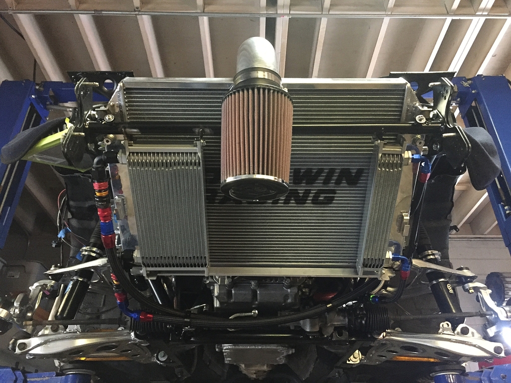
There's still a bunch of assembly to be done before it's driving (rear end, suspension, interior, etc.) but we're close to first test start. All that's left is wiring... not a small thing but I can feel it getting close!
Current view from the front:
Current view from the front:
Reply
4
4
02-08-2017, 12:03 AM
#479
Supporting Vendor
Thread Starter
iTrader: (3)
Join Date: Jul 2006
Location: San Diego
Posts: 3,303
Total Cats: 1,216
Hoping that I don't 
Will be monitoring trans and diff temp and will add if necessary. Regarding the front stack, it's a relatively traditional layout... less complicated than my previous V-mount setup. I'm enjoying the simplicity that comes with a non boosted motor in that regard.
Will be monitoring trans and diff temp and will add if necessary. Regarding the front stack, it's a relatively traditional layout... less complicated than my previous V-mount setup. I'm enjoying the simplicity that comes with a non boosted motor in that regard.
Reply
0
0
03-10-2017, 01:11 PM
#480
Supporting Vendor
Thread Starter
iTrader: (3)
Join Date: Jul 2006
Location: San Diego
Posts: 3,303
Total Cats: 1,216
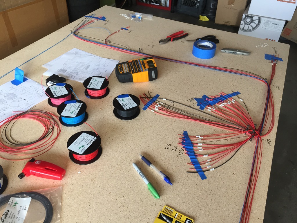
Apologies for it being quiet for a little while, I've been spending long hours building the wiring harness. I wanted to be rid of the hacked up factory wiring mess once and for all so I chose to take the long road and removed every wire from the car, because now was the right opportunity to take the extra time and learn how to build good motorsports wiring from the ground up.
For now, here's a pic from way back on step 1 with wires laid out for the new chassis harness:
For now, here's a pic from way back on step 1 with wires laid out for the new chassis harness:
Reply
0
0


