crank case pressure
 12-11-2007, 04:12 PM
#1
Elite Member
Thread Starter
iTrader: (5)
Join Date: Jan 2005
Location: Atlanta
Posts: 7,482
Total Cats: 372
I've got oil leaking from the front of the cam cover near where the rtv goes at the cams... again. That's the bad leak. It's also seeping around the entire cam cover and around the filler cap. It's been doing this for a while but the leak near the cams is bad enough to get on the tbelt. I'm running a turbo supra PCV valve which is still in good operating condition (just checked it). I've had my cam cover vent running through a catch can to the intake pre turbo and now the can is just venting. I hardly get any oil- maybe a tablespoon in 500 miles. Compression is still ~185 across the board - as it was before the turbo.
What I have noticed is that in 1000 miles my cam cover gasket is far harder than it was new as installed. I can only assume this is from the heat. So that might explain the seepage. But I suspect there's enough pressure going on to make the leaks far worst than w/o boost.
I'm wondering if anybody else sees any evidence of crankcase pressure like this. And has anybody taken other measures to improve the crankcase venting. It seems that just about all the other turbo cars out there get some kind of venting upgrade when the boost goes up or when they go from NA to boost. For example- a lot of the hondas get a big (AN12) hole right in the cam cover to a catch can that vents back to the OE pvc/vent system.
Looking at the mazda cam cover, it looks very restrictive in allow this venting with it's internal chambers for the pvc and vent. I've got a spare cam cover, so I'm seriously considering something invasive that will allow easy ejection of the gases from the crankcase like I've seen on the hondas. - rob

Reply
 0
0

0
 12-11-2007, 05:45 PM
#4

Run the turbo PCV system and the breather to turbo tube and you won't have the same problem. Put a 3/8" filter or a catch can between the breather and turbo, no oil in turbo, same with PCV. Crankcase will see negative pressure during vacuum and boost.
I was going to mention blowby as the problem, but saw you did a compression test. A couple sessions before piston 4 let go in an old engine, small amounts of oil leaked from the filler cap, more after each session. Then the 4th session of the day did it in, and things turned very smokey.
I was going to mention blowby as the problem, but saw you did a compression test. A couple sessions before piston 4 let go in an old engine, small amounts of oil leaked from the filler cap, more after each session. Then the 4th session of the day did it in, and things turned very smokey.
Reply
0
0
12-11-2007, 05:51 PM
#5
I can guarantee you that the crankcase will not see vacuum in boost with the breather replumbed. The lowest pressure you will ever see in a boosted car is by VTA with the breather. If you make is a closed system by plumbing into the intake pressure will increase with time.
Reply
0
0
12-11-2007, 09:09 PM
#6
Elite Member
Thread Starter
iTrader: (5)
Join Date: Jan 2005
Location: Atlanta
Posts: 7,482
Total Cats: 372
Plumbing from the can to the intake pre turbo is damn near the same thing as vta. Most turbos don't have much of a intake length. I had mine run that way with a good 45* angle on it in the intake and then just stuck a filter on the can in place of the intake tube and there was no difference. The reality is that crank case pressure is just that- pressure. And it's way more pressure than most of these pcv/vent systems were designed to manage. It will find a way out, and is, but it just needs a bigger "pipe" to get out quicker.
I'll go ahead and set up the spare cam cover with some big *** barb ports on it and dump into a can and see what happens. If anybody sees any clever solutions to blocking oil passage through these ports, post them up.
I'll go ahead and set up the spare cam cover with some big *** barb ports on it and dump into a can and see what happens. If anybody sees any clever solutions to blocking oil passage through these ports, post them up.
Reply
0
0
12-11-2007, 10:02 PM
#7
Boost Czar


iTrader: (62)
Join Date: May 2005
Location: Chantilly, VA
Posts: 79,490
Total Cats: 4,079
are you certain it's not your cam seals....
rob, look at the diagram i posted in the last pcv thread....the one with the long title and response. i'd link but this "free" internet in my hotel is slower the 28kb.
rob, look at the diagram i posted in the last pcv thread....the one with the long title and response. i'd link but this "free" internet in my hotel is slower the 28kb.
Reply
0
0
12-12-2007, 10:44 AM
#9
Elite Member
Thread Starter
iTrader: (5)
Join Date: Jan 2005
Location: Atlanta
Posts: 7,482
Total Cats: 372
I'll look again. It's possible, given how oil spreads about in the vicinity of spinning parts. And the cam seals are ancient, not to mention they sat dry for two years.
Reply
0
0
12-13-2007, 05:22 PM
#10
Elite Member
Thread Starter
iTrader: (5)
Join Date: Jan 2005
Location: Atlanta
Posts: 7,482
Total Cats: 372
I removed the vent chamber covers from the cam cover and took some pics. Looking at the overall picture, it looks like the pcv chamber sees way more action. Of course this might be from vacuum at high rpm. BUT it's half the size, has a much larger entry, far less baffles (2 vs. 6) and a much larger exit than the vent side. Also noticed that the vent chamber exit has a much smaller hole in the cam cover than what appears on the outside connection. It's almost half the size- about 3/16".
The small exit hole and numerous baffles must be a big restriction on pressure trying to exit while the pcv exit is block under boost. So at this point I'll plug the pcv bung on the intake manifold and then route the cam cover pcv port to the catch can (vta) to supplement the venting. Thoughts?
Cam cover with chamber covers flopped out:

Cam cover exit vent side:

PCV chamber entry:

The small exit hole and numerous baffles must be a big restriction on pressure trying to exit while the pcv exit is block under boost. So at this point I'll plug the pcv bung on the intake manifold and then route the cam cover pcv port to the catch can (vta) to supplement the venting. Thoughts?
Cam cover with chamber covers flopped out:
Cam cover exit vent side:
PCV chamber entry:
Reply
0
0
 12-13-2007, 10:27 PM
#13
Elite Member
Thread Starter
iTrader: (5)
Join Date: Jan 2005
Location: Atlanta
Posts: 7,482
Total Cats: 372
Yes. Though I wouldn't be surprised to see similar designs on the B engines. Easy enough to try out on either, though nobody else seems to be seeing anything like this on the B. I should have a chance to try it out before the weekend.
Reply
0
0
12-15-2007, 08:01 AM
#14
Junior Member

Join Date: Feb 2007
Location: 11368 miles from where i would like to be
Posts: 269
Total Cats: 92
I couldnt find those pics that i thought i took. perhaps i never took them. either way, it doesnt matter as yours are of the utmost quality anyway :-)
Further to discussing this with both Rob and Brian last night, i was thinking about what i might do for one when i get back.
Currently i just have the longer labyrinth with the short oem hose hanging in mid air doing nothing much at all, and the oem pcv setup to my manifold much like stock.
For a number of reasons i believe its beneficial to have the pcv valve in place and functioning in some place or other. the pcv gasses can be greasy and oily with no negative impact on anything much, so the small labyrinth is probably best left supplying that in the long term.
its apparent from Robs fine pics that the longer labyrinth and its associated escape route are rather small and restrictive. most likely totally fine for normal NA use, but if you double the power it would be reasonable to double the blowby and therefore with nothing else changed double the velocity of gas through that port under load. given a tripling of power, probably a similar tripling of flow would be needed to keep pressures oem low.
in order to achieve tripple the flow at the same near 100kpa pressure you would need approximately tripple the area to pass it. thats not going to happen through that stock rear port.
my proposed solution is this :
oem pcv as it stands
rear port enlarged as much as reasonably possible
inside of rocker at the front of the head ported where that gas enters the labyrinth to slow the flow sufficiently to allow the oil to fall out
some porting of the baffles in the big labyrinth to ease velocity in there.
and lastly :
having had a think about it and a good look at Robs pics and my own, it would appear that the only decent place to put an extra port on the fe3 cam cover is at the rear of the intake cam. they were nice enough to put a cast in wall across in front of it to keep the oil away, and because its adjacent to the end of the cam no oil will be being flung there are high revs.
an exhaust scavenging system installed on this new port, or just another catch can and VTA (vent to atmo) setup.
given these mods you end up with the following situation :
throttle closed at idle/trailing throttle :
pcv draws dirty (wet) gas out of the crank case and clean air enters the original feed that goes to the turbo intake or vta. either the check valve on the exhaust scavenger is closed and no flow occurs or it too is scavenging some gas and disposing of it.
effect : clean air entering the case on one side, and dirty air exiting where it doesnt matter
result : engine oil stays cleaner and more effective longer because moisture is scavenged out at idle and on trailing throttle
throttle open wide scenario one :
pcv closed due to pressure in the manifold being 100kpa or greater
exhaust scavenging pulls so much gas out that clean air flows in through vta/vtt (vent to turbo) and crank case is kept clean under throttle too.
throttle open wide scenario two :
pcv closed due to pressure in the manifold being 100kpa or greater
exhaust scavenging pulls in exact gas that is being blown by and nothing flows through vta/vtt
throttle open wide scenario three :
pcv closed due to pressure in the manifold being 100kpa or greater
exhaust scavenging pulls in a bunch of gas, but not enough to prevent pressure buildup or more flow.
VTT/VTA dumps excess to atmo or turbo inlet
in this way you end up with low pressure at all times and clean air flowing in to replace wet blow by whenever opportune.
its possible that the exhaust scavenger would always be enough, this could be tested with the vta/vtt blocked and a sensitive pressure guage installed in the cabin and watched while thrashing the car hard.
thats my take on it.
fred.
Reply
0
0
12-15-2007, 10:54 AM
#15
Elite Member
Thread Starter
iTrader: (5)
Join Date: Jan 2005
Location: Atlanta
Posts: 7,482
Total Cats: 372
Sounds like a good solution to me. Am I wrong for thinking that the crankcase pressure goes far beyond double when you add (even moderate) boost? Don't know if the B cam covers have a similar wall cast in place, but that does look like the ideal spot for a new vent location.
I took the car out yesterday with this setup: ran the pcv valve in line on what was the vent line (more restrictive) and used the OE pcv port as the vent port to the vta catch can. Made several runs to ~5k at full throttle, and one run from low rpm to rev limit. There was no evidence of oil anywhere- not at the vta filter on the can, any gasket/seals nor the oil filler cap on the cam cover. I'll get to make some harder runs tomorrow.
I took the car out yesterday with this setup: ran the pcv valve in line on what was the vent line (more restrictive) and used the OE pcv port as the vent port to the vta catch can. Made several runs to ~5k at full throttle, and one run from low rpm to rev limit. There was no evidence of oil anywhere- not at the vta filter on the can, any gasket/seals nor the oil filler cap on the cam cover. I'll get to make some harder runs tomorrow.
Reply
0
0
12-15-2007, 01:40 PM
#16
Junior Member
Join Date: Feb 2007
Location: 11368 miles from where i would like to be
Posts: 269
Total Cats: 92
rob, my memory was faded when i said "rbs get boxs welded on the top" half right :-)
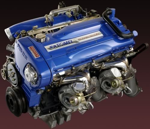
they have boxs cast in from factory on the rb26 model :-) i couldnt find any serious plumbing pics of them, but the factory arrangement is fairly serious in the first place :
thats what i meant anyway.
fred.
they have boxs cast in from factory on the rb26 model :-) i couldnt find any serious plumbing pics of them, but the factory arrangement is fairly serious in the first place :
thats what i meant anyway.
fred.
Reply
0
0
12-17-2007, 09:51 AM
#17
Elite Member
Thread Starter
iTrader: (5)
Join Date: Jan 2005
Location: Atlanta
Posts: 7,482
Total Cats: 372
I'll bet the head is similar to the FE with a valley separating both sides - thus the tube for equalizing and releasing pressure on both sides. The B engines don't have a valley where the intake and exhaust are mostly isolated.
Reply
0
0
12-17-2007, 10:14 AM
#18
Junior Member
Join Date: Feb 2007
Location: 11368 miles from where i would like to be
Posts: 269
Total Cats: 92
yeah, it is, there are 6 coils under that cover.
what that picture doesnt show is that off the outer side of each upright, comes a hose. the exhaust side one goes to the turbos/inlet, and the intake side one goes to a pcv setup of some sort i think.
this is how its done on a modded setup

not sure that i'd do it that way, but...

you can see the valley and coils there

and the intake and turbo vents there
fred.
what that picture doesnt show is that off the outer side of each upright, comes a hose. the exhaust side one goes to the turbos/inlet, and the intake side one goes to a pcv setup of some sort i think.
this is how its done on a modded setup
not sure that i'd do it that way, but...
you can see the valley and coils there
and the intake and turbo vents there
fred.
Reply
1
1
12-17-2007, 11:56 AM
#19

Hi,
I would add to the recommendation that it would be beneficial to find vacuum from somewhere for the crankcase. Exhaust side and even vacuum pumps are widely used in Drag Race engines and David Wizard showed the positive effects on power measured in dyno once vacuum was introduced into crankcase. It is pressure difference between the top and bottom of the piston, which makes it move.
hrk, still here and lurking
Reply
0
0
12-17-2007, 01:31 PM
#20
Elite Member
iTrader: (9)
Join Date: Jun 2006
Location: Chesterfield, NJ
Posts: 6,892
Total Cats: 399
I've seen vacuum/scavange kits (Vibrant) that use a venturi like insert into a O2 sensor bung that supposedly gives you around 3" Hg on some setups. Uses 8AN line. I'd think you'd need a lot of exhaust velocity to make any significant gains, but who knows, seems easy to try compared to vacuum pumps for maybe some gains.
Reply
0
0


