
Standalone 1.6 Wiring Diagram / Schematic


Thread Starter
Junior Member
iTrader: (6)
Joined: Aug 2008
Posts: 248
Total Cats: 3
From: New Zealand
I have seen so many adapted versions of the DB37 MS wiring Schematic but none of them have been complete for a standalone.
This is what I have made. I hope it can help others.
My wiring is only 80% complete in real life so if this needs correction, tell me and I will fix up.

This is what I have made. I hope it can help others.
My wiring is only 80% complete in real life so if this needs correction, tell me and I will fix up.
Last edited by ogwazza; Jan 19, 2009 at 04:44 AM.
Reply
 0
0

0


There needs to be a separation of grounds. Coils, widebands, fuel injectors, and fans are examples of high current devices. Coils and fuel injectors in particular can cause noise in the system as current draw can change drastically in a short period of time.
Sensors, such as coolant temp, air temp, TPS, signal side of wideband, etc are low current devices. These devices use very small currents and are sensitive to anything that would induce a current into the device as this would skew its' reading.
Examples:
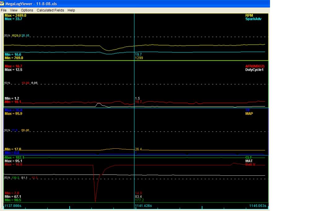
Here's a datalog. Notice that "battery voltage" spikes down very low, very sharply, and then goes back to normal. This was causes by noise from low ohm injectors causing MS to skip-a-beat.
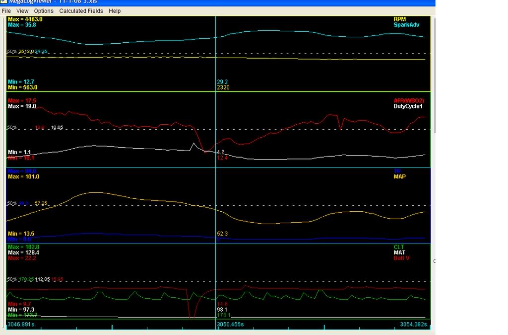
Here's another example of noise causing problems. Check out the "CLT" reading. It's constantly changing on the graph, rhythmiclly. Of course the engine's coolant temp isn't really changing that drastically. In this case, bad spark plug wires were causing noise.
Anyways, it's a good idea to keep high current/noisy components grounded separately from signal grounds.
EDIT: And gap the plugs at 0.020", not 0.20"
 .
.
Reply
0
0


Joined: Sep 2005
Posts: 34,428
Total Cats: 7,548
From: Chicago. (The less-murder part.)
Within the MS circuit board, all grounds are common. There is some separation of the ground plane itself, but at the DB-37, all the ground pins are tied together. Thus, the only way to achieve separation of the sensor and logic grounds from the high-current (injector, IDL, etc) grounds would be to lift the ground leads of the devices in question and bring them out to a separate connector.
I agree that in theory having isolated grounds would be nice, and it chafes me somewhat that whoever laid out the 3.0 PCB didn't do this, but in practice it seems not to matter. Just run several heavy ground leads from the MS to the ground point on the intake manifold and connect them across all the ground pins at the DB37.
I agree that in theory having isolated grounds would be nice, and it chafes me somewhat that whoever laid out the 3.0 PCB didn't do this, but in practice it seems not to matter. Just run several heavy ground leads from the MS to the ground point on the intake manifold and connect them across all the ground pins at the DB37.
Reply
0
0

What gauge and how many ground wires should I run through the firewall for the MS and my LC1? I'm grounding my LC1 through the stock ECU grounds and it resets on startup (i'm assuming it should not).
I think i might install my MS today finally.
I think i might install my MS today finally.
Reply
0
0
Joined: Sep 2005
Posts: 34,428
Total Cats: 7,548
From: Chicago. (The less-murder part.)
I've heard about there being problems with the LC1 during startup, though I've not experienced them personally as mine is wired to a lead that's off during cranking.
Based solely upon intuition, I'd posit that the problem is likely related to supply voltage rather than ground. When the starter is turning, it creates so much load that it pulls the battery voltage down. How far depends largely on the type and condition of the battery, but it's not uncommon for one that's a few years old to fall to 8 or 9 volts during cranking. My suspicion is that the LC1 is intolerant of such a low supply voltage and craps out.
In my car, I have a wire running from the battery, through a relay, to the LC1 and XD16. The relay is controlled by the wire which supplies power to the radio. Thus, with the key in ACC or RUN the LC1 is on, but in the START position it switches off. This seems to keep it quite happy.
The LC1 needs to be grounded to the same wire as the ECU, as close as possible to the ECU. The reason is that any differential in ground potential will be expressed as an offset in the analog signal passing from the LC1 to the ECU, which will throw off your readings.
I don't think there's a hard-and-fast answer to the grounding question. In my car, I am connected to two of the stock ECU grounds, and also to two new pieces of 14 or 16ga wire (can't remember which) that I ran direct to the head. All four hit the MS's ground pins in common. The LC1 and XD16 are grounded (with a vampire tap) to one of these ground wires a few inches from the DB37. In this configuration, I get no processor resets and no obvious noise on the analog signals, and the MS seems to read AFR quite accurately.
Reply
0
0

Reply
0
0
Thread Starter
Junior Member
iTrader: (6)
Joined: Aug 2008
Posts: 248
Total Cats: 3
From: New Zealand
What about pulling it from the Ign Blk/white. It powers the Radio and the cigar and only turns on once the ignition is on.
According to the pics the white/red wire should only have power to it once the green/white relay has opened ( the green/white wire should be hot at all times tho
for the full schematic see * Tom Madracki's Discount Computer Repair Service
.... yes it does seem that your main relay would be stuck on, or else a crossed wire somewhere
Reply
0
0
Reply
0
0
Thread Starter
Junior Member
iTrader: (6)
Joined: Aug 2008
Posts: 248
Total Cats: 3
From: New Zealand
... good point- I dunno as I dont own a miata, makes sense tho- my nissan did that.
Ok swap it to Blu wire. (will that work?!!) I was thinking ignition cos its so close to the MS (usually) and its easy- just pull out the plug- push a wire into the end and bobs your uncle!! no soldering required!
Thats how we like to do things down here in Kiwi land!
Ok swap it to Blu wire. (will that work?!!) I was thinking ignition cos its so close to the MS (usually) and its easy- just pull out the plug- push a wire into the end and bobs your uncle!! no soldering required!
Thats how we like to do things down here in Kiwi land!
Reply
0
0
Reply
0
0
Did you not try wiring it to the white wire with a red stripe (point 1B on the diagram on post #3 in this thread)? That should have been the correct power wire that is switched and on during cranking? Everything has worked perfectly for me with my diagram. Your wiring should be exactly the same as mine (I've got a 91) unless your miata is from california.
Thanks alot for that diagram though helped alot in wiring my car.
Reply
0
0


