Intake Manifold Ideas
 09-29-2009, 11:39 PM
#1
Elite Member
Thread Starter
iTrader: (2)

Join Date: Jan 2007
Location: Lexington, SC
Posts: 2,075
Total Cats: 0
So I was reading up on this thread:
Turbo Intake Plenum - HybridZ
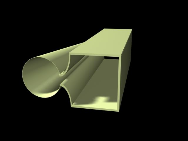
And thought I would throw something together that looked like it could be cheap. This was made in 3DS Max so I don't intend it to be very technical, I would rather use Inventor for in depth stuff. This is merely a drawing if you will, just three dimensional.
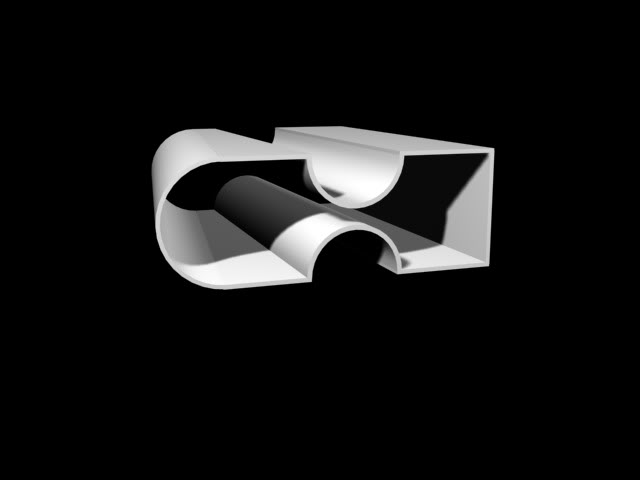
This manifold is just for me (for now) and I tried to design it so that I could make it fairly cheaply down the road. The only draw back I have found is how in the hell am I going to cut pipe down the middle for such a length? Also feel free to put up any input if you want. I know it needs to be properly drawn in Inventor, CAD, or ProE or something of the sort then run some flow tests on it, but I am just fiddlin' around. If I get bored I may add the runners
Turbo Intake Plenum - HybridZ
And thought I would throw something together that looked like it could be cheap. This was made in 3DS Max so I don't intend it to be very technical, I would rather use Inventor for in depth stuff. This is merely a drawing if you will, just three dimensional.
This manifold is just for me (for now) and I tried to design it so that I could make it fairly cheaply down the road. The only draw back I have found is how in the hell am I going to cut pipe down the middle for such a length? Also feel free to put up any input if you want. I know it needs to be properly drawn in Inventor, CAD, or ProE or something of the sort then run some flow tests on it, but I am just fiddlin' around. If I get bored I may add the runners

Reply
 0
0

0
 09-30-2009, 12:18 AM
#3
Elite Member
Thread Starter
iTrader: (2)
Join Date: Jan 2007
Location: Lexington, SC
Posts: 2,075
Total Cats: 0
The design was/is used on Audi rally cars, I found this useful:
Photo Album
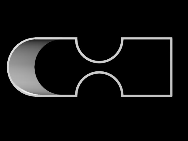
I am not afraid to admit that my design lacks a "smooth conical taper", but its a WIP
Photo Album
The primary lower plenum with connects to the throttlebody is gradually tapered like a cone with a continuous single vent slot that allows gas to pass into the 2nd plenum. The 2nd plenum acts as a collector which then feeds the runners to the head. Pressure in the 2nd plenum is equallized since its not effected by gas velocity and inertia or the pressure variation from front to back of the 1st plenum. Since flow equals velocity times area. The reduction in flow which is released through the side slot is equal to the reduction in area of the plenum assuming velocity is constant. So a smooth conical taper with establish equal pressure and air distribution into the 2nd plenum.
Reply
0
0
09-30-2009, 01:35 AM
#4
Elite Member
Thread Starter
iTrader: (2)
Join Date: Jan 2007
Location: Lexington, SC
Posts: 2,075
Total Cats: 0
Well this may flow better whenever I decide to make something that matters
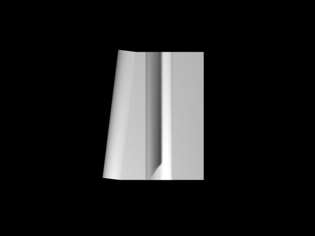
Bend this sheet into this and...
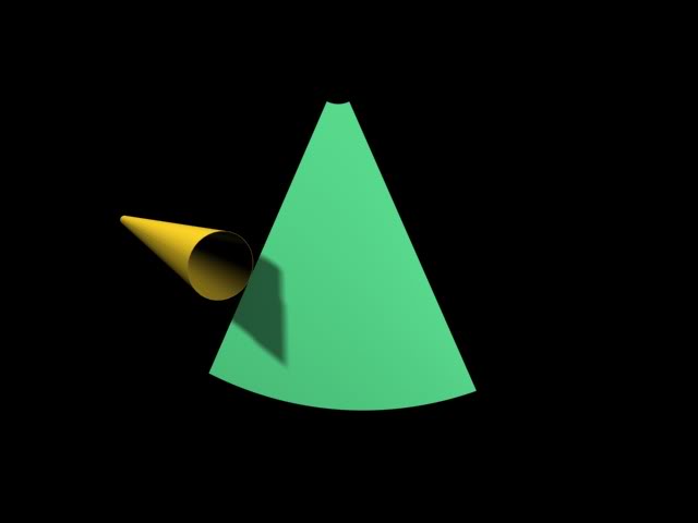

voila
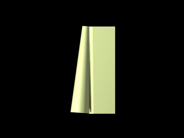
In reality what you see before you could be made with 1 large piece of sheet and a length of pipe. But reality often doesn't work this way. Anyways this method should eliminate any CNC ($$$) machinery being required and rely on nothing but hammers and a welder.
Now an area of the project that I am undecided about is the area that back wall that will connect to the runners. Making it round and flowy would look amazing, and you could imagine nice cool air slipping over the shiny metal ready to give your engine more umph. But in that HybridZ build the guy ran into problems with the air in the runners chamber swirling (see page 4 of that thread). I am hoping that the flat back will kick any air that tries that **** in the *****.
Bend this sheet into this and...
voila
In reality what you see before you could be made with 1 large piece of sheet and a length of pipe. But reality often doesn't work this way. Anyways this method should eliminate any CNC ($$$) machinery being required and rely on nothing but hammers and a welder.
Now an area of the project that I am undecided about is the area that back wall that will connect to the runners. Making it round and flowy would look amazing, and you could imagine nice cool air slipping over the shiny metal ready to give your engine more umph. But in that HybridZ build the guy ran into problems with the air in the runners chamber swirling (see page 4 of that thread). I am hoping that the flat back will kick any air that tries that **** in the *****.
Reply
0
0
 09-30-2009, 03:12 AM
#6
Elite Member
iTrader: (1)

Join Date: May 2009
Location: Jacksonville, FL
Posts: 5,155
Total Cats: 406
There may need to be some consideration put into the ends of the rectangular part of the plenum, if the ends are flat their is a possibilty of unwanted resonance forming along its length, which I think could be minimized by making the ends curved, bulged, or some other organic shape.
One thing that has always concerned me about having a 'tapered' plenum (such as in this, and other designs) is how critical is the shape and angle of the tapered plenum?
Essentially the reasoning behind the tapper is that (starting at the inlet) the first quarter of the plenum length has to flow air to all four cylinders, while the second quarter only needs to flow enough for 3, and so on. So, my first instinct from a design standpoint would be to have the volume of the first quarter to be 4 times the volume of the last quarter. But then you have to think about possible wasted volume at the inlet due to turbulence from the transition through the throttle, or increased (porportional?) thickness of the boundary layer towards the end of the plenum...
Their are just so many unknowns, I wonder if its naive to think it would work very well the first try
Reply
0
0


 09-30-2009, 11:24 AM
#11
Elite Member

iTrader: (9)
Join Date: Jun 2006
Location: Chesterfield, NJ
Posts: 6,893
Total Cats: 399
So I was reading up on this thread:
Turbo Intake Plenum - HybridZ
And thought I would throw something together that looked like it could be cheap. This was made in 3DS Max so I don't intend it to be very technical, I would rather use Inventor for in depth stuff. This is merely a drawing if you will, just three dimensional.
This manifold is just for me (for now) and I tried to design it so that I could make it fairly cheaply down the road. The only draw back I have found is how in the hell am I going to cut pipe down the middle for such a length? Also feel free to put up any input if you want. I know it needs to be properly drawn in Inventor, CAD, or ProE or something of the sort then run some flow tests on it, but I am just fiddlin' around. If I get bored I may add the runners
As far as cutting a long straight pipe in half, just make a template, it'd be real easy. You know the circumference. Take half of it, and the length, and cut a rectangular paper template from an appropriate piece of paper. Wrap around the pipe & tape if needed, draw a line with a sharpie. Cut.
Reply
0
0
09-30-2009, 01:42 PM
#12
Elite Member
Thread Starter
iTrader: (2)
Join Date: Jan 2007
Location: Lexington, SC
Posts: 2,075
Total Cats: 0
 I am just getting some ideas down on my hard drive at the moment. I haven't tackled the ends yet because I thought it would be easier for people to grasp the general shape without them and also because I am not quite sure what I will do with them yet. I can't wait to get it into an engineering design program yet and probably won't be able to until January. But if anybody gets impatient or is feeling nice and wants to design it and CFD it for me, than I will help any way possible
  Thanks for the advice Tim! I am debating in a local car forum about injector location and whether each runner should have its own throttle body. Chime in with whatever you guys think.
Reply
0
0

Thread
Thread Starter
Forum
Replies
Last Post


