More COP Problems (HELP!)
 10-20-2008, 10:20 PM
#1
Elite Member
Thread Starter
iTrader: (11)

Join Date: Jun 2007
Location: Overland Park, Kansas
Posts: 5,360
Total Cats: 43
As some of you know I'm one of maybe three in the Miata community that failed to get a Toyota COP conversion working. Dismissed my problems as maybe an issue with the built in ignitor and gave up.
Heres what happened: Followed Brains writeup and wiring to an absolute T, just didn't include the tach wiring because my car doesn't use it. The coil connector is only 4 positions, +12, GND, T1, T2. Wired T1 to coil number 1 and 4. Soldered my connections, heat shrunk, then tested with a DVM. Absolutely 0 ohms resistance between the main plug and coils 1 & 4. Did the same for T2, only wired it to Coil 2 and Coil 3. Soldered, heat shrunk, checked. +12, Gnd. The gnd comes from the coils connector to the firewall, and cars harness both so theres a good ground. Checked on the car at each coil connector for +12, cont to ground, and all is good.
Installed all 4 coils, wired up, ready to go. Cranks, no ignition at all. Checked my ignition setting which are identical to Scotts writeup (and what I've been running on stock coils for 13 months now...) no spark. Pulled the number 1 coil out of the spark plug hole and stuck a screwdriver in it, placed it near a ground. Cranking the car it does not spark. Unplug number 4 coil and crank, number one sparks like a mad mother. Plug 4 back in, No spark. Reversed, unhooked number 1 and tested number 4 with its connector.. Sparks like a mad mother. Plug in 1 and no spark. Moved to 2 and 3, got the same results. If both coils are hooked up at the same time, they WILL NOT FIRE. Checked for frequency, get a very nice strong +5volt Square wave.
Went back and checked all my wiring for resitance, none. Wiring used for the trigger is 2x larger than the factory spec for the pair of coils, so they should carry more than enough current. Same with +12 and GND.
Ordered another set of coils, different P/N this time from an RX300. They came today so I tried again. Laughed at myself when I was done hooking it all up, said "it won't spark." Guess what... THEY DON'T FREAKING SPARK!
If everything is wired perfectly, they'll sprak without being run in parallel with its sister coil, WHAT THE **** IS THE PROBLEM!?
Someone please help.. I'm really losing my bloody mind here.

Reply
 0
0

0
10-20-2008, 10:28 PM
#2
Here's what you need to do. You need to get out a piece of paper and draw up a nice, pretty, organized wiring diagram of exactly how you have the setup wired. Show where all the connections are, etc. Label everything neatly. Ruler and a pen it will take about an hour. Scan it and post it up. Label where your sources are. (ex, +12V from... , GND from back of cylinder head, etc. )
Reply
0
0
10-21-2008, 12:15 AM
#3
Elite Member
Thread Starter
iTrader: (11)
Join Date: Jun 2007
Location: Overland Park, Kansas
Posts: 5,360
Total Cats: 43
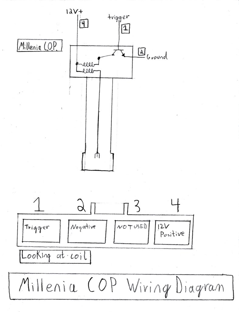
My drawing isn't that great, but I did my best and tried to label everything possible so theres no confusion at all.


Yeah, the bolt isn't installed at the grounding point because none of the harness is there. I've attempted different grounding points, also. One on the back of head, firewall, etc. No change.
Yeah, the bolt isn't installed at the grounding point because none of the harness is there. I've attempted different grounding points, also. One on the back of head, firewall, etc. No change.
Reply
0
0
10-21-2008, 12:44 AM
#4
Before we progress, if we do get it going, I want one of the sets of coils, ok? I seriously need some COPs. I have my own ignition woes with damn EDIS... And can't find two millenia COPs to save my life.
Strange problem you have there. So MS is firing the coils, right? Is it a MSPNP or a custom built MS? Did you build it? Is it a parallel install?
If it's a parallel install, try switching back to let the stock ECU fire the COPs and see what happens.
Also, try running a fused +12V wire from the battery to the coils, bypassing the cars factory wiring.
And this to me makes the most sense to me (read, I'm probably wrong and full of ****). Try putting a 1K resistor between the coils trigger wire and +12V. This will act as a pull up. The megasquirt should be doing something like this already I would imagine, but couldn't hurt to try.
Also, have you tried running .020" gap with the COPs?
Last edited by patsmx5; 10-21-2008 at 01:16 AM. Reason: I'm an 11 month baby
Reply
0
0
10-21-2008, 01:59 AM
#5
Elite Member
Thread Starter
iTrader: (11)
Join Date: Jun 2007
Location: Overland Park, Kansas
Posts: 5,360
Total Cats: 43
I'm running a full standalone MS v2.2 that I built myself. Like I said earlier, I've been driving the car for more than a year on the megasquirt with factory coils. As you might notice I don't have a factory valve cover, and with the breather port exiting the rear of the cover its in the way of factory coils, so they won't go there and be secure. I resorted to using security wire to attach them together, then attach them to the strut bar. The wires are getting old and its missing a lot under cruise plus I want a hotter spark.
Cars running on .035" gap right now just fine with factory coils, but the COPs won't even spark if both in the trigger parallel are plugged in with a screwdriver test.
I like the ideas of the +12 volt and the pullup resistor, since the fused 12 volt will be the easiest I'll make sure to try that one first. Maybe if I'm lucky it'll fire right up.
My little mini-vacation (haha.) is over so I must return to work tomorrow, but after Taco night I'll make sure and give it another shot then report back. Not holding my breath.
Oh, if I can get a set of these freakin things workin, we'll work something out for sure.
Reply
0
0
10-21-2008, 02:04 AM
#6

If i read ur diagram correctly all the coils are powered via paralel lines off of the main factor line right. Or did u run the serial? If you ran them serial maybe the voltage is bleeding off on the first plug before it gets to the second one. A test for this would be to monitor your voltage with one coil conected and see if you keep the right amount. I ran mine parralel and had noproblems getting a nice strong fire.
Reply
0
0
10-21-2008, 03:55 AM
#7
Elite Member
Thread Starter
iTrader: (11)
Join Date: Jun 2007
Location: Overland Park, Kansas
Posts: 5,360
Total Cats: 43
Tried my best to make sure to illustrate they're wired in parallel with the exception of a 5" pigtail to the connector where its one wire. Key on, Engine off all coils have same voltage across the board, though the last time I tested this (back over winter) cranking voltage to the coils was kind of low and I still suspect this might be a problem. IIRC it was around 9vdc during cranking with all 4 coils hooked up. I'll test that one again, just to make sure.
Reply
0
0
 10-21-2008, 05:30 PM
#10
Elite Member
Thread Starter
iTrader: (11)
Join Date: Jun 2007
Location: Overland Park, Kansas
Posts: 5,360
Total Cats: 43
Okay heres the score.
Jumpered +12 from the battery straight to the +12 input for the coils bypassing the factory +12 in the harness. Put a DVM on it and cranked. Get 11 volts or so with no spark on any coils. Unhooked 1, 3 and the car started for a few seconds, granted it was rough.. then died. Hook 1 and 3 back up, no spark. Hooked up a scope to the trigger at the cars harness portion of the ignition connector and checked frequency on cranking with all 4 coils plugged in. Get a +5 volt square wave, looks perfect on both spark outputs. Backprobed all 4 coil plugs with the coils plugged in and hooked the scope up. Perfect +5 volt square wave, none of the four sparked. Removed and unhooked all four coils. Hooked up 1 and 3 with screwdrivers. Cranked, they spark. A lot. Unhooked them and switched to 2 and 4 with screwdrivers. Spark, a lot. Hook up 1 and 3 with screwdrivers in 2 and 4. No spark.
Put factory coils and plug wires back on, car started without thinking twice.
Reply
0
0
 10-21-2008, 09:07 PM
#13
Like I said, post your settings and spark inputs/output circuits you're running. Hell, this could end up being a wrong setting or a missing resistor or something simple. You say your running V2.2 not V3.0. I'm not familiar with that version as I am with my MS2 V3.0. Most here don't run my or your setup.
Reply
0
0
10-22-2008, 04:35 AM
#14
Elite Member
Thread Starter
iTrader: (11)
Join Date: Jun 2007
Location: Overland Park, Kansas
Posts: 5,360
Total Cats: 43
Sorry, Man, I'm just getting seriously pissed off at this.
I'm not doing anything any different than anyone else on this forum, and it just won't ******* work. Thats why I'm so upset and the complete and total lack of help from someone with experience that might've had some problems / solutions is even more frustrating.
I'm running a MS V2.2 with the standard Miata mods for ignition. Have driven over 20,000 miles and 13 months with it. Works fine, starts everytime. I wired my megasquirt just like everyone else did for their miata, only on a 2.2 instead of 3.0.


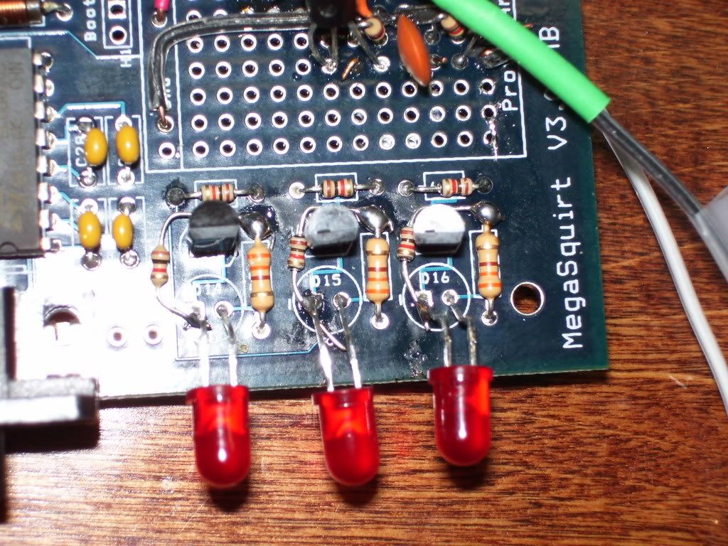
The two resistors are mounted under the board, the two (red/yellow) wires travel across the top and interface with the DB37 connector. Those are the typical miata spark output mods, which, start the car perfectly fine on stock coils. Yes, the flux has been removed from the bottom of my board. That photo was taken November 2007.

I wired up the coils just like everyone else did following the multiple threads on the ******* things found on this forum.


Modified my Pins and built my harness after that exact wiring diagram.

Used that chart, along with every post with megasquirt success running these pieces of **** on megasquirt.
I've put an oscilloscope on the ignition triggers for the ******* coils with everything hooked up in the order it would be if the engine was running. The triggers are showing a strong +5 volt square wave trigger, which, is what megasquirt puts out on a bench test with stimulator. Tested all four coils with the scope, on the car, on a cranking condition. Unhooked one of the two in the series and the +5 volt square wave looks identical as before, with all hooked up. Checked for +12 volts at the coils during cranking, with the scope hooked up to the triggers. They've got plenty of voltage during cranking, around 10 - 11.4 volts. Jumped from the battery in the trunk a 4 gauge power wire straight to the +12 volt input for the coils. Made no difference. Put my battery charger on the battery, with the jumper wire still in place and selected the 50 amp booster selection on the charger. Cranked the engine for 30 - 50 seconds straight never once getting a coil to fire.
Sometimes, if I'm cranking away at this **** and unhook one of the coils with the ignition still on, it'll fire the coil with a wonderful shotgun sound from my exhaust. The neighbor loves that.


Those are my spark settings. They work perfect with factory coils. I changed the dwell for cranking from everything at .5ms to 10ms. Nothing makes the coils spark while all hooked up.
Deinstalled the coils / harness from my car and plugged it into my friends car with a brand new DIY MSnS-PNP. Guess what... NO ******* SPARK! Removed it from his car and installed it on a car with FACTORY PCM. NO SPARK.
Now if anyone has any ******* suggestions please, by all means, feel free to chime in because I'm spent. At this point I don't see how anyone has ever had success getting these ******* things to work on their megasquirt, MUCHLESS FACTORY ******* PCM!
Understand why I'm so frustrated and pissed off?
I'm not doing anything any different than anyone else on this forum, and it just won't ******* work. Thats why I'm so upset and the complete and total lack of help from someone with experience that might've had some problems / solutions is even more frustrating.
I'm running a MS V2.2 with the standard Miata mods for ignition. Have driven over 20,000 miles and 13 months with it. Works fine, starts everytime. I wired my megasquirt just like everyone else did for their miata, only on a 2.2 instead of 3.0.
The two resistors are mounted under the board, the two (red/yellow) wires travel across the top and interface with the DB37 connector. Those are the typical miata spark output mods, which, start the car perfectly fine on stock coils. Yes, the flux has been removed from the bottom of my board. That photo was taken November 2007.
I wired up the coils just like everyone else did following the multiple threads on the ******* things found on this forum.
1 ground
2 trigger
3 tach
4 +12V
2 trigger
3 tach
4 +12V
Used that chart, along with every post with megasquirt success running these pieces of **** on megasquirt.
I've put an oscilloscope on the ignition triggers for the ******* coils with everything hooked up in the order it would be if the engine was running. The triggers are showing a strong +5 volt square wave trigger, which, is what megasquirt puts out on a bench test with stimulator. Tested all four coils with the scope, on the car, on a cranking condition. Unhooked one of the two in the series and the +5 volt square wave looks identical as before, with all hooked up. Checked for +12 volts at the coils during cranking, with the scope hooked up to the triggers. They've got plenty of voltage during cranking, around 10 - 11.4 volts. Jumped from the battery in the trunk a 4 gauge power wire straight to the +12 volt input for the coils. Made no difference. Put my battery charger on the battery, with the jumper wire still in place and selected the 50 amp booster selection on the charger. Cranked the engine for 30 - 50 seconds straight never once getting a coil to fire.
Sometimes, if I'm cranking away at this **** and unhook one of the coils with the ignition still on, it'll fire the coil with a wonderful shotgun sound from my exhaust. The neighbor loves that.
Those are my spark settings. They work perfect with factory coils. I changed the dwell for cranking from everything at .5ms to 10ms. Nothing makes the coils spark while all hooked up.
Deinstalled the coils / harness from my car and plugged it into my friends car with a brand new DIY MSnS-PNP. Guess what... NO ******* SPARK! Removed it from his car and installed it on a car with FACTORY PCM. NO SPARK.
Now if anyone has any ******* suggestions please, by all means, feel free to chime in because I'm spent. At this point I don't see how anyone has ever had success getting these ******* things to work on their megasquirt, MUCHLESS FACTORY ******* PCM!
Understand why I'm so frustrated and pissed off?
Reply
0
0
10-22-2008, 07:22 AM
#15
Junior Member

Join Date: Mar 2006
Location: Sydney Australia
Posts: 138
Total Cats: 0
I may be (and usually am) completely off, but in the wiring diagrams for a 1995 (I have a 1990) here it shows the wire you've labelled #3 on the facory connector as a black/white and the tach sense. If you are grounding this, then that could be why your spark is not working, but when you remove one of the coils from gnd (or the spark plug) then you eliminate the short on the signal.
I could be way off, but just try running the cop grounds straight to the chassis and brak the strap on pin #3 to gnd.
I could be way off, but just try running the cop grounds straight to the chassis and brak the strap on pin #3 to gnd.
Reply
0
0
 10-22-2008, 09:38 AM
#17
Boost Czar


iTrader: (62)
Join Date: May 2005
Location: Chantilly, VA
Posts: 79,493
Total Cats: 4,080
I'm wondering if you can replace the 1K resistors on your spark mod with 470ohm or even 100ohm resistors to send out a stronger current.
https://www.miataturbo.net/forum/sho...2&postcount=38
I'm currently running a MS with 470ohm resistors....obviously (as Joe stats) the MSPNP is using less.
https://www.miataturbo.net/forum/sho...2&postcount=38
I'm currently running a MS with 470ohm resistors....obviously (as Joe stats) the MSPNP is using less.
Reply
0
0
 10-22-2008, 10:38 AM
#19
And +1 to ampz comment. Black with white wire from the factory wiring diagram goes to both coils and the tachometer. It should never go to ground. Plus, if you had it hooked up, you'd have to have a pair of fast switching diodes inside so that one tach signal didn't bleed into the other.
Reply
0
0


