NB Cat Delete CEL fix question
 01-24-2009, 10:36 AM
#21
Supporting Vendor


iTrader: (33)
Join Date: Jul 2006
Location: atlanta-ish
Posts: 12,659
Total Cats: 134
Leave o2 sensor in place. Snip signal out wire and replace signal with analog output from appropriately programmed LC1. Done.
I'm dong this, but a bit more complicated as I'll have the LC1 "move" switchpoint up one point from stoich to 15.7:1. Not a problem to fool the computer on both sensor since LC1 has 2 analog outputs.
I'm dong this, but a bit more complicated as I'll have the LC1 "move" switchpoint up one point from stoich to 15.7:1. Not a problem to fool the computer on both sensor since LC1 has 2 analog outputs.


Reply
 0
0

0
01-24-2009, 06:38 PM
#23
Slowest Progress Ever
iTrader: (26)
Join Date: Oct 2007
Location: The coal ridden hills of Pennsylvania
Posts: 6,022
Total Cats: 304
My 99 had 2 cats from the factory. I cut off the 2nd cat, and used a piece of pipe to replace it. The 2nd O2 sensor is after the 1st cat. When I went turbo, I replaced my stock manifold and DP with aftermarket ones, which now I am catless. This made my CEL come on. I bought a simulator. Then I went to the local u-pull-it and snipped the pigtail off an O2 sensor that fit my car. The I wired the simulator directly to the pigtail and plugged it in to the secondary O2 harness on my car. I hid it so Mr. Inspection can't see it. I don't have a CEL anymore.
Reply
0
0
01-25-2009, 10:23 PM
#24
I was totally happy with my simulator. I used a resistor instead of the sensor to save a bit of weight, and then all the wiring was under the dash instead of running it out under the car. Can't say I minded it, though my standalone also doesn't turn on the CEL, and I have a used O2sim for sale. :-)
Reply
0
0
01-25-2009, 10:29 PM
#25
Moderator

iTrader: (12)
Join Date: Nov 2008
Location: Tampa, Florida
Posts: 20,646
Total Cats: 3,009
I was totally happy with my simulator. I used a resistor instead of the sensor to save a bit of weight, and then all the wiring was under the dash instead of running it out under the car. Can't say I minded it, though my standalone also doesn't turn on the CEL, and I have a used O2sim for sale. :-)
Reply
0
0
06-24-2010, 12:09 AM
#26

A simulator is illegal, so whatever I write in this post is purely hypothetical. This fix may or may not be working great in my car. 
Car had a CEL for "emissions too close to threshold" or something like that after a few months with a high-flow metalcore cat.
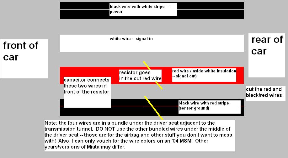
Under the driver's seat, very close to the trans tunnel, is a plastic-wrapped series of four wires. This is where the wires exit the car and go underneath to the rear O2 sensor.
Cut open the plastic wrap. The four wires (on an '04 at least) are: 1., black with white stripe (power), 2., white (signal in), 3., red (mostly wrapped in a second layer of white insulation - signal out), 4., black with red stripe (sensor ground).
Cut the red and black/red wires. Install a 1 megaohm resistor (1/4-watt or 1/2 watt) in the red wire. Then install a 1 microfarad capacitor jumping the red and black/red wires, forward of the resistor. Cover the wires with electrical tape or (better yet) heat-shrink tubing. I used electrical tape but I'm told it could melt over time.
Done.
This sends an acceptable voltage to the ECU, so it thinks all is well. (These aren't the droids we're looking for .... move along .....)
Car had a CEL for "emissions too close to threshold" or something like that after a few months with a high-flow metalcore cat.
Under the driver's seat, very close to the trans tunnel, is a plastic-wrapped series of four wires. This is where the wires exit the car and go underneath to the rear O2 sensor.
Cut open the plastic wrap. The four wires (on an '04 at least) are: 1., black with white stripe (power), 2., white (signal in), 3., red (mostly wrapped in a second layer of white insulation - signal out), 4., black with red stripe (sensor ground).
Cut the red and black/red wires. Install a 1 megaohm resistor (1/4-watt or 1/2 watt) in the red wire. Then install a 1 microfarad capacitor jumping the red and black/red wires, forward of the resistor. Cover the wires with electrical tape or (better yet) heat-shrink tubing. I used electrical tape but I'm told it could melt over time.
Done.
This sends an acceptable voltage to the ECU, so it thinks all is well. (These aren't the droids we're looking for .... move along .....)
Reply
0
0
 06-29-2010, 01:57 PM
#28
Cut the red and black/red wires. Install a 1 megaohm resistor (1/4-watt or 1/2 watt) in the red wire. Then install a 1 microfarad capacitor jumping the red and black/red wires, forward of the resistor. Cover the wires with electrical tape or (better yet) heat-shrink tubing. I used electrical tape but I'm told it could melt over time.
also i have a 63v microfarad capacitor laying around, will that do the job? it's also polarized so witch wire would go into the + side?
edit: didn't see page 2 with a sweet ms paint how to.
Last edited by jeff_man; 06-29-2010 at 03:03 PM.
Reply
0
0
12-23-2011, 11:24 PM
#30
Newb

Join Date: Sep 2011
Posts: 4
Total Cats: 0
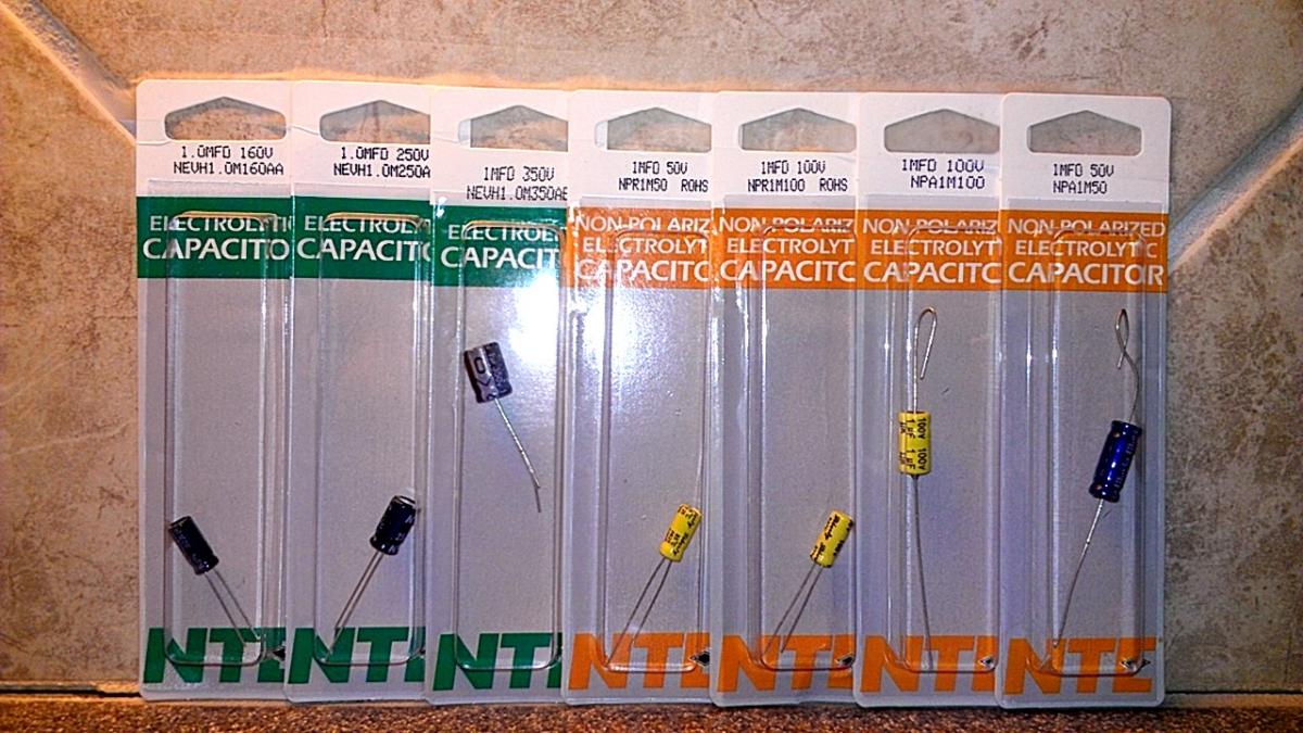
I am going to do this CEL mod on my 04 MSM (no cat) but had a question about whether I should use a polarized or non-polarized capacitor. Also, the capacitors range from 50v to 350v so I wasn't sure which one to use. I am hoping that based on the picture below, someone can tell me which one they successfully used to complete this mod. Thanks for your help!
Reply
0
0
12-24-2011, 12:45 PM
#31
Boost Pope

iTrader: (8)
Join Date: Sep 2005
Location: Chicago. (The less-murder part.)
Posts: 33,019
Total Cats: 6,587
Also, the capacitors range from 50v to 350v so I wasn't sure which one to use.
Reply
1
1
12-26-2011, 06:36 PM
#33
Junior Member

Join Date: Dec 2007
Location: Santa Fe, TX
Posts: 101
Total Cats: 3
What voltage does the ECU want to see from the post-cat O2 sensor signal line to make it happy? (The cat I have is somewhat "less than optimal" from the ECU's point of view as compared to the original OEM cat + the post-cat O2 sensor has been abused to death...or maybe the wrong one, I don't know but I'm tired of f'cking around with it - it is inspection time again dammit).
Last edited by secretsquirrel; 12-26-2011 at 06:51 PM.
Reply
0
0
04-06-2012, 11:21 PM
#34
Newb

Join Date: Jan 2012
Posts: 21
Total Cats: 2
sorry for bringing up a dead thread...but after reading this, i had a question.
after putting that cap between the red/black and red wire, do you just leave the part of the red/black wire that goes to the sensor itself unhooked? or do you re-solder it to the node/joint where the cap is already soldered to the red/black wire?
after putting that cap between the red/black and red wire, do you just leave the part of the red/black wire that goes to the sensor itself unhooked? or do you re-solder it to the node/joint where the cap is already soldered to the red/black wire?
Reply
0
0
04-09-2012, 02:23 AM
#35
Elite Member
iTrader: (2)
Join Date: May 2008
Location: Portland, Oregon
Posts: 3,468
Total Cats: 365
There are mini-cats now that go between the bung and the O2 sensor. Much easier than fooling the ECU or jacking with the wires ... the O2 sensor sees exhaust air that is post-cat, like it's supposed to. The main cat can then be deleted if so desired.
Edit: Mini cat from Big Daddies Garage.
Dynotronics makes one as well; appears to be of higher quality but significantly more expensive.
Edit: Mini cat from Big Daddies Garage.
Dynotronics makes one as well; appears to be of higher quality but significantly more expensive.
Reply
0
0

Thread
Thread Starter
Forum
Replies
Last Post
Zaphod
MEGAsquirt
47
10-26-2018 11:00 PM
Greasyman
General Miata Chat
2
09-28-2015 10:44 AM


